

Abstract
Recent experiments show that the conformation of filament proteins play a role in the motility and morphology of many different types of bacteria. Conformational changes in the protein subunits may produce forces to drive propulsion and cell division. Here we present a molecular mechanism by which these forces can drive cell motion. Coupling of a biochemical cycle, such as ATP hydrolysis, to the dynamics of elastic filaments enable elastic filaments to propagate deformations that generate propulsive forces. We demonstrate this possibility for two classes of wall-less bacteria called mollicutes: the swimming of helical-shaped Spiroplasma, and the gliding motility of Mycoplasma.
INTRODUCTION
Polymer filaments play an important role in prokaryotic morphology and motility (Jones et al., 2001). The most well-characterized of these is the bacterial flagellum, a helical structure that, when rotated, produces the thrust that propels many swimming bacteria (Namba and Vonderviszt, 1997). However, some bacteria swim but do not possess flagella. Some, like Spiroplasma, a wall-less bacteria, are themselves helically shaped and swim by dynamically changing the conformation of their helical body, sometimes propagating contractile waves that travel the length of the cell (Davis, 1979; Gilad et al., 2003; Trachtenberg and Gilad, 2001). Another class of mollicutes, the Mycoplasmas, move by ‘gliding’ over surfaces. The speediest of these bacteria, Mycoplasma mobile, can move at speeds of up to 4 μm/s (∼4 body lengths per second). Their propulsive organelle is located in a protrusion that projects from the anterior of the cell (Miyata and Uenoyama, 2002). Other bacteria, like the cyanobacterium Synechococcus, are cylindrical and propel themselves with no discernable propulsive organelle. Calculations have shown that surface waves can produce sufficient force to propel Synechococcus (Ehlers et al., 1996; Stone and Samuel, 1996), but no known mechanism can produce such waves.
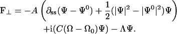
Recently, a number of polymer filaments have been discovered in bacteria that appear to have important functional roles. FtsZ is a protein necessary for bacterial septation and division. It normally forms a ring at the center of the bacterial cell at the beginning of division. During the transition to sporulation, FtsZ undergoes a cyclic transition from a ring located at the center of the cell, to a helix, and then back to a ring located near one end of the cell (Ben-Yehuda and Losick, 2002). This allows for the asymmetric division associated with the formation of a spore. FtsZ is known to be a GTPase and it is believed that GTP binding may induce morphological transitions in the filament conformation (Lowe and Amos, 1998). In Spiroplasma, a ribbon made up of seven protofilaments provides the structural rigidity for the cell. The subunits of the ribbon are present in more than one conformation (Trachtenberg and Gilad, 2001).
Here we present models for the locomotion of this class of swimming and gliding organisms. The models are based on the presence of a filamentous elastic polymer composed of subunits, each of which can be chemically triggered to undergo a conformational change. There are two possible mechanisms for this mechanochemical coupling. Experiments suggest that motility in Spiroplasma may be coupled to the membrane potential (Beven and Wroblewski, 1997; Trachtenberg, 1998). Therefore, it is possible that the local ionic environment is the chemical trigger for conformational change. However, DCCD, an inhibitor of the Fo portion of ATP synthase, also inhibits motility (Trachtenberg, 1998). As such, it is possible that motility is driven by nucleotide hydrolysis, rather than directly by the transmembrane ion motive force. Until this ambiguity is resolved, we will construct our models such that either energy source can produce the conformational changes required for locomotion. That is, the filaments driving motility might constitute a linear array of NTPases, or be driven directly by the membrane potential that controls the local ionic conditions. The analysis would be similar in either case. For a hydrolysis-driven filament transducer, binding of a nucleotide, GTP or ATP, to a subunit induces an elastic stress that tends to deform it. The rate of binding and product release can depend on the local stress. For a filament that responds to local ionic conditions, the triggering stimulus can be provided by ionic leaks accompanying changes in the membrane potential, or by mechanoactive ion channels. We will show that the coupling between the local chemical state of the subunit and the conformation of the filament can produce bending and compression deformations that are capable of producing propulsive forces sufficient to explain the swimming and gliding of these bacteria. The models lend themselves to a variety of experimental tests.
Spiroplasma: a swimming helix
One of the simplest living organisms, Spiroplasma is a helical mollicute bacterium (Trachtenberg, 1998). A cholesterol-containing unit membrane defines the cell body; however, there is no periplasm providing rigidity for the cell. Instead, the cell's helical shape is defined by a protein ribbon lying just under the membrane, and probably anchored to it. This ribbon is composed of seven protofilaments connected side by side. Each protofilament is comprised of a linear chain of subunits that can take on multiple conformations (Trachtenberg and Gilad, 2001). This microscopic structure of the ribbon is similar to the structure of the bacterial flagellum, a long helical filament that is rotated to produce thrust in many swimming bacteria. The bacterial flagellum is composed of 11 protofilaments with each protofilament comprised of subunits of a single protein, flagellin. The flagellin subunits have been observed to take on two separate conformations (Samatey et al., 2001): they are bistable. Unlike the ribbon in Spiroplasma, the 11 protofilaments in the flagellum are connected into a helical tube. The structure of the bacterial flagellum combined with the bistable nature of the subunits produces 12 possible morphological configurations for the flagellar filament (Calladine, 1975). When torque is applied to the flagellum, as occurs when the motor that turns the flagellum switches direction or under some flow conditions, the flagellum morphology changes. When the rotary motor that turns the flagellum switches direction, the flagellum undergoes a “flip” between helical forms that initiates at the end of the filament near the cell body and travels to the far end of the flagellum (Macnab and Ornston, 1977). Similar transformations also occur when fluid is flown past a flagellum with sufficient velocity (Hotani, 1982). Recent theoretical work has shown how external flow can produce the flipping behavior observed by Hotani (Coombs et al., 2002; Goldstein et al., 2000).
In Spiroplasma, the ribbon lies along the path of minimum distance along the helical surface of the cell. This is a result of the ribbon being the principal elastic component and can be understood using an energetic argument (see Appendix A). The most effective mode of propulsion in Spiroplasma is by propagating traveling kinks (Gilad et al., 2003). Kinks are a natural result of abrupt changes in either pitch or radius of curvature along a helix (Goldstein et al., 2000). Because changes in pitch correspond to compression or extension of the helix, it is likely that these kinks are equivalent to the traveling compression waves that were observed to produce rotational motions in Spiroplasma (Davis, 1979). Since the cell operates at very low Reynolds numbers, uniform compression and extension would not produce net motion (Purcell, 1977), and so compression waves provide the asymmetry required for propulsion in viscous media.
The cell body shape is slave to the conformation of the protein ribbon; motion of the protein ribbon directly determines the motion of the cell body. Therefore, the mechanism driving motility must generate changes in the radius of curvature, R, and pitch, P, of the ribbon that travel. We suggest two possible mechanisms by which this could occur.
Mechanism 1
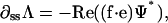
The protein ribbon is a chain of elastic subunits, where the preferred local conformational state of the filament (e.g., pitch and/or curvature) is controlled by the local chemical conditions (e.g., hydrolysis state of the filament subunits or local ionic conditions). Thus, the local curvature and torsion of the ribbon are dependent on the local chemical state. Conversely, the chemical binding rate depends on the stress in the filament. This produces a coupled system where the stress determines the chemical rate and the chemical state sets the preferred conformation of the filament. The equations governing the motion of the helix are given in Appendix B; they have the forms:
Figure 9.

Figure 10.

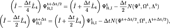
In Eq. 1, v is the velocity, σ is the local stress, and ɛ(t) is the local strain in the filament. The function γ(ξ) describes how the stress depends on the local chemical state, ξ(x,t), and the function f(ɛ(x,t)) describes how the stress affects the reaction rate. Equation 2 describes the chemical cycle, whose rate constants depend on the local strain. The particular functional forms of these equations are given in Appendix B. Fig. 1 a (inset) shows a few frames from a computed movie of the shape of the helical bacterium driven by the compression wave that propagates from the proximal to the distal end (See Supplemental Material for the full movie).
FIGURE 1.
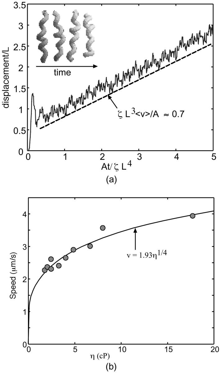
Application of the active helical filament model to the swimming of Spiroplasma. (a) The graph plots the displacement of the center of mass in the direction of the helix axis as a function of time, and shows the average propulsive velocity is positive and roughly constant. The insert shows frames from the movie of the flexing helix (for movie, see the Supplemental Material). (b) Plot of speed versus specific viscosity for Spiroplasma. The dots are data taken from Gilad et al. (2003), and the dashed line is 0.98(η/ηH2O)1/4. See Appendix C for details.
Mechanism 2
The subunits in the Spiroplasma ribbon are bistable. Calladine's model suggests that the ribbon has eight separate morphological states (Calladine, 1975). Local conditions such as ionic concentration can shift the bistable potential such that, at high ionic concentration, one conformation is energetically favored, but at lower ionic concentrations the other state is favored. If the ribbon is entirely in one state and the ionic conditions shift such that that state is no longer energetically favored, then if one part of the ribbon is driven locally to flip states, this induced flip in curvature and/or pitch will propagate, as is seen in bacterial flagella. Whereas mechanism 1 produces an active motion of the filament that is chemically driven at every point along the ribbon's length, this mechanism requires only an ionic oscillation (such as is described in Appendix G) and a local flipping at one point to produce wave motion. Because the ribbon has multiple stable conformational states, this change in pitch will propagate down the length of the cell producing a train of traveling pitch waves along the ribbon (Coombs et al., 2002).
One possible experiment that could distinguish between Mechanisms 1 and 2 would be to impose an external torque or flow on the Spiroplasma cell body. If one end of a Spiroplasma cell is tethered to a coverslip and fluid is flown past the cell, then the structural ribbon should periodically flip its handedness if the ribbon has multiple stable conformations, similar to experiments done on bacterial flagella (Hotani, 1982).
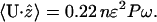
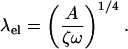
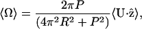
Regardless of the mechanism, traveling pitch waves can drive the motility of Spiroplasma. Using the force from low Reynolds number hydrodynamics and the drag on the oscillating helix, an approximate average swimming speed can be calculated from knowing the frequency of the pitch wave. For physical parameters appropriate for Spiroplasma, we find that the cycle driving the pitch wave needs to oscillate at ∼40 s−1 to produce a swimming speed of 1.2 μm/s (see Appendix C). Also, the rotational velocity of the cell can be estimated based on this theory. For the same physical parameters, we find that the cell body should rotate at an angular frequency of ∼2.7 s−1 (see Appendix C). This theory suggests two experimentally testable predictions. First, the cell should travel in the direction of the pitch wave. Second, the model also suggests that the translational speed produced by traveling pitch waves increases with viscosity as U ∝ η1/4, where U is the translational velocity along the helix axis and η is the viscosity. Experiments show that the speed does increase with viscosity (Daniels, 1980; Gilad et al., 2003) in accordance with the theory (See Fig. 1 b); however, more experimental data is needed to verify this scaling. We also simulated the model proposed by Mechanism 1 numerically and calculated the force that is produced along the axis of the helix. Since the velocity of the filament is proportional to the total force, the integral of the force, with respect to time, is proportional to the displacement of the cell. Fig. 1 shows the computed displacement of the flexing filament in the direction of the helix axis. The calculation is carried out in detail in Appendix C. The oscillations in the displacement are due to when the helix compresses; the force is directed opposite to when it extends. However, because the compression/extension cycle propagates as a wave, these competing factors do not cancel, and there is a total average propulsive force on the helix which produces a net velocity, 〈v〉.
Gliding motility of Mycoplasma
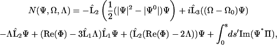
A number of bacterial species propel themselves over solid substrata without visible motile organelles, a process generically called gliding (Mcbride, 2001). Mycoplasma, also a mollicute bacterium like Spiroplasma, glides on solid surfaces (Trachtenberg, 1998). It is a pear-shaped cell with an anterior ‘nose’ projection. In some species the nose contains a filament bundle (diameter ∼40–120 nm) running from the anterior pole to the cell body, where it fans out into individual filaments (see Fig. 2; see also Shimizu and Miyata, 2002; Mayer, 2003). The filament bundle is periodically organized with parallel striations of 12–14 nm, analogous to those in Spiroplasma, although the mycoplasmas do not contain spirillen, the contractile protein in Spiroplasma. The cell adheres to host cells at the tip where there is a dense structure from which the filament bundle emanates. In Mycoplasma mobile, the fastest of the mycoplasmas, a filament bundle has not been identified, but the nose appears to encase a filament meshwork. Miyata and Berg measured the force-velocity properties of the propulsion motor in M. mobile, as well as its temperature-dependence (Miyata et al., 2002). They found three distinguishing features of the motor for the ranges of load and temperature they used (Fig. 2):
The load-velocity relation is nearly linear with a stall force of ∼25 pN.
Load-velocity curves measured using viscous drag loads at different temperatures extrapolated to the same stall force. Independently, laser trap experiments confirmed the value of the extrapolated stall force.
The velocity increased nearly linearly with temperature.
Here we show that mechanochemical filaments can also be adapted for propulsion over surfaces. In contrast to the spirillen filament bundle in Spiroplasma, these filaments appear to be organized into a less structured organelle in Mycoplasma mobile. However, by ascribing mechanosensitive properties to the filamentous structure, we can construct a model that reproduces the measured properties of the propulsion motor. The model assumptions are as follows:
The anterior part of the filament bundle (the ‘nose’) can generate a contractive or expansive elastic stress according to the local chemical environment. This can be a bending or a contraction stress (see Fig. 2 a and Discussion), either of which result in shortening and lengthening the effective length of the nose.
The filament stress is coupled to a chemical cycle. For example, a membrane-associated ‘pacemaker’ at the tip of the nose generates a periodic membrane potential that cyclically alters the chemical environment of the anterior filament bundle. This signal triggers the elastic deformation of the filament bundle. The chemical cycle may be autonomous, or coupled to the stress (e.g., by stress-activated ion channels). In Appendix G, we give a concrete example of such a mechanochemical oscillator.
The same chemical trigger that initiates the filaments' contraction also activates attachment of the tip to the substratum. Thus the membrane pacemaker induces a coordinated cycle of attachment and contraction followed by detachment and relaxation (Fig. 2 b).
We model the attachment of the anterior filament bundle to the cell body by an elastic element (see Fig. 2 c) so that the cell body exerts a drag on the filament motor in series with the force-generating filament bundle and with the load force applied externally to the cell.
We assume the friction force on the cell to be of three types: 1), the fluid drag acting directly on the cell and on the attached bead; 2), a kinetic friction due to the attachment and detachment of adhesion proteins to the substratum (Tawada and Sekimoto, 1991), which accounts for most of the drag; and 3), a sliding friction characterized by a yield force, Fyield. This friction force allows the body to stay attached to the glass during those parts of the cycle when the tip is detached. It represents the resistance to motion from the chemical attachment and detachment of the transmembrane adhesive proteins (Tawada and Sekimoto, 1991).
FIGURE 2.

Gliding motility of Mycoplasma mobile. (a) Schematic representation of propulsive and attachment organelle in Mycoplasma containing filament bundle. The filament bundle can elongate and shorten by bending or by longitudinal shortening, e.g., due to filament unbundling and entropic contraction. In either case, the projected length alternates between lengths L1 and L2, producing a step size of δ = L2 − L1. (b) Schematic of the proposed mechanochemical cycle for the cell. The filament bundle attaches at the front and contracts, stretching the cell body. The elastically coupled cell body slides forward, consolidating the forward step. Finally, the nose detaches and extends, completing the cycle. The mathematical model given in Appendix E follows the sequence of events shown in the figure. Triggered by the periodic membrane potential, the mechanochemical deformation of the filament bundle can occur in several ways. (c–d) Load velocity curves for bending (c) and contraction (d) deformations for the no-slip (solid line) and back-slip (dashed line) models. The data points are from Miyata et al. (2002) for two temperatures. In both cases, the model extrapolates to the same temperature-independent stall force of ∼25–27 pN. The details of the simulation and parameters used are given in Appendix E.
The motion of the cell body is described by the mechanical equation
 |
(3) |
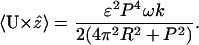
Here V is the velocity of the cell body, ζ is the fluid drag coefficient on the cell, and FM is the force generated by the filament motor. We assume that the motor force is in elastic equilibrium with the elastic force, Fel, in the spring that couples the cell body to its attachment to the force-generating nose. Ffr is the friction force due to adhesion of the body to the substrate, and Fload is the external load force applied to the bacteria. In Appendix E we give explicit expressions for these forces. Solving Eq. 3 allows us to approximate the average velocity, 〈V〉, of the cell as the frequency of the mechanochemical cycle, f(T), × the step size, δ, giving the net displacement during one cycle:
 |
(4) |
For the stall force, δ(Fstall) = 0, to be temperature-independent, the step size, δ, depends on the load force, but only weakly on the temperature, T. Thus the pacemaker frequency contains most of the temperature-dependence. The cycle of stepping is illustrated in Fig. 2 b.
Fig. 2, c and d, shows that the computed model velocity is nearly linear in the load force, as observed by Miyata et al. (2002). Two attachment conditions to the surface produce the observed force-velocity relationship. If the yield force, Fyield, exceeds the stall force then the load directly stalls out the motor, which is tightly coupled to the cell motion. However, if the yield force, Fyield, is smaller than the stall force, when the nose is detached the cell slips backward. Stalling occurs when the rate of back-slipping when the nose is detached equals the rate of forward stepping when the nose is attached. The motor is then loosely coupled to the cell motion. Experiments with laser trapping and finer optical resolution can discriminate between these two possibilities.
Miyata et al. also found that, over a range of ∼30°C, the velocity increased nearly linearly with temperature (see Appendix E; Miyata et al., 2002). To fit their data, the frequency of the cycle must increase with temperature, whereas the rest of the parameters remain nearly constant. To make the stall force independent of temperature in the back-slip model, the rate-limiting temperature-sensitive step of the chemical cycle takes place while the tip is attached. More information on the exact biochemical nature of the pacemaker is necessary to model the temperature-dependence of the cycle. A likely candidate is a membrane pacemaker that imposes periodic changes in the local ionic environment in the nose to initiate the bending/contraction directly or by regulating an ATPase cycle. Appendix G gives an example of how this could work using mechanosensitive ion channels, several of which are known to exist in bacteria. Multibarrier kinetics for different pumps and channels composing the oscillator can generate nearly linear temperature-dependence over the observed range. Moreover, the frequency of excitable membranes, as modeled by the Hodgkin-Huxley equations, show nearly linear temperature-dependence, although over a somewhat narrower range.
DISCUSSION
We have presented models for bacterial swimming and gliding based on the idea of an active filament that can generate mechanochemical deformations sufficient for propulsion. There is precedent for such filaments in eukaryotic cells (Mahadevan and Matsudaira, 2000), but prokaryotic mechanochemical filaments constitute a new class of protein motors that may play the role of the eukaryotic filament-based motors, such as myosin and kinesin. Our models of these motors necessarily has been somewhat phenomenological since no such motor has been analyzed in sufficient biochemical and structural detail to allow analysis in more depth. Nevertheless, the models can fit the available experimental data.
We have been necessarily ambiguous about the mechanism of mechanochemical coupling since experiments have barely addressed, let alone resolved, the issue. However, analogies from other biological systems provide some clues. Several prokaryotic filament types are known to be NTPases; therefore, it is easy to imagine that nucleotide binding can produce a bending stress analogous to that developed in F1-ATPase (Oster and Wang, 2003). However, this is not the only possibility. Both the Spiroplasma and Mycoplasma models depend on a mechanochemical oscillator at one pole of the cell to initiate the deformation cycle. We consider the most likely candidate to be a mechanochemical oscillator arising from the coupling between the filaments that generate the mechanical stresses and the cell's plasma membrane. The ubiquity of mechanosensitive channels in bacteria suggests the possibility of an oscillating membrane potential arising from membrane stress induced by the mechanical filaments (Bass et al., 2002; Perozo et al., 2002a,b); an example of how this feedback can create a self-sustaining oscillation is given in Appendix G.
Local ionic conditions can couple directly to filament stress in several ways. One of the earliest examples is the mechanochemical engine of Katchalsky and others that used local ionic conditions to control a cycle of entropic contraction and expansion of collagen fibers (Rubin et al., 1969; Steinberg et al., 1966; Sussman and Katchalsky, 1969). More generally, ionic conditions control the volume expansion and contraction of many polyelectrolyte bio-gels, especially in secretory granules (Verdugo, 1991; Verdugo et al., 1987a,b). Divalent cations are especially potent de-swelling agents for polyelectrolyte gels (Nguyen et al., 1998). Several models have been proposed for cellular propulsion based on the ion-controlled expansion and contraction of polyelectrolyte gels (Bottino et al., 2002; Joanny et al., 2003; Moriyama et al., 1999; Wolgemuth et al., 2003). A similar mechanism may operate in the nose of M. mobile during its expansion-contraction cycle. (A rough estimate of the maximum force that can be generated by a contracting/expanding gel can be obtained as F ∼ kBT/Lδφ0(V/Vm); see Wolgemuth et al., 2003. Here kB is Boltzmann's constant, T is the temperature, δφ0 is the change in gel volume fraction, V is the volume of the gel, Vm is the size of a monomer of the polymer in the gel, and L is a length scale for the problem. Assuming the volume fraction of a gel is φ0 ∼ 0.1 and ∼10% expansion/contraction, we estimate δφ0 ∼ 0.01, and Vm ∼ 0.1 nm3. The length of the propulsive organelle is ∼0.1–0.3 μm long and 10−4 μm3 volume. From this we estimate that F ∼ 100 pN.) All that needs to be added is a mechanism by which contraction is synchronized with adhesion to the substratum. For example, divalent ion salt bridges could form between the contracting filament network and a transmembrane adhesion protein known to be present in M. mobile (Seto and Miyata, 2003; Shimizu and Miyata, 2002).
The notion of an active filament motor may apply to other kinds of bacterial locomotion. Below we speculate on two other motile systems, one swimming, one gliding.
Synechoccocus
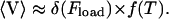
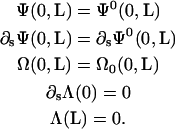
The cyanobacterium Synechococcus is an ellipsoidal-shaped bacterium that swims without flagella or visible changes in shape, driven by a sodium-ion motive force (Willey et al., 1987). This is not inconsistent with the possibility that NTP hydrolysis is the mechanochemical energy source, since the manufacture of ATP by ATP synthase depends on a sodium motive force in several bacterial species (Dimroth et al., 1999). It has been suggested that traveling waves on the surface of the cell body could provide the thrust required for motility (Ehlers et al., 1996), but no mechanism for generating these waves was proposed. Recently, Samuel and co-workers discovered 5-nm diameter spicules spanning the periplasm and projecting out from the cell up to 150 nm into the surrounding fluid (Samuel et al., 2001). They hypothesized that these spicules could oscillate to produce a traveling surface wave sufficient to propel the cell.
We suggest the surface waves are driven by mechanochemical filaments located near the inner membrane of the cell similar in design to that proposed for the protein ribbon in Spiroplasma. By binding and unbinding of a molecule such as ATP or GTP, or by changes in the local ionic environment, this filament locally bends. If the spicules are attached to the mechanochemical filament, bending of the filament will cause the spicules to move, and the bending wave from the filament will be transmitted to the outside surface of the cell by the spicules (see Fig. 3). If the spicules are assumed rigid, the motion of the cell can be directly related to the motion of the mechanochemical filament. Therefore, we can model this filament and its chemical state in a similar fashion to the Spiroplasma model. We treat the filament as an elastic filament whose preferred curvature depends on its chemical state. We confine the elastic filament to two dimensions and assume small amplitude deformations. The equations governing the bending wave propagation have the same form as Eqs. 1 and 2. The solutions to these equations show traveling waves related to the natural rate of the chemical system. A few frames from the computed wave are shown in Fig. 3 b; a movie of the compression wave is given in the Supplemental Material. If we assume that the filament is an ATPase, then the oscillation frequency for the spicules is of the order of a few milliseconds. This is the predicted surface wave frequency obtained from the hydrodynamic calculation (Ehlers et al., 1996). The propulsive thrust that can be produced by these types of waves has been calculated (Ehlers et al., 1996; Stone and Samuel, 1996). Using their result to estimate the swimming velocity one obtains V ≈ 10 μm/s, close to that observed.
FIGURE 3.
Application to the swimming of Synechoccocus. (a) Cartoon showing how the internal bending wave is translated by the spicules into an external compression/amplitude wave. (b) Computed bending wave moving from left to right. The plot shows the conformation of the active filament at three time steps with chronological order (solid line, dotted line, and dashed line; for movie, see the Supplemental Material).
Myxobacteria
Myxobacteria have two gliding systems: so-called S (social) and A (adventurous) motility. A number of mechanisms have been proposed for this kind of motility, but only one has been demonstrated unequivocally: S-motility is driven by the extension and retraction of Type 4 pili, which are fueled by ATP hydrolysis (Kaiser, 2000; Mcbride, 2001). A-motility is also inhibited by azide, an ATP inhibitor (Sun et al., 1999).
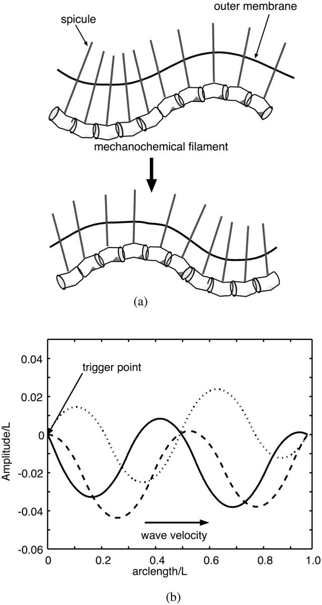
Micrographic examination of Myxococcus cells reveals a helical filamentous structure wrapping the periplasmic space (Burchard et al., 1977; Freese et al., 1997; Lunsdorf and Reichenbach, 1989; Lunsdorf and Schairer, 2001. These filaments appear in two conformational states, so they are a candidate for the gliding motility system of these organisms. There are at least two mechanisms that can utilize these helical filaments to make myxobacteria cells elongate/shrink. First, the helical structures observed by Lunsdorf and co-workers could exert a circumferential stress that squeezes the cell causing it to elongate and narrow by a few percent (see Fig. 4). Second, a membrane, or mechanochemical oscillator can drive propulsion by cyclically raising and lowering the internal osmotic (turgor) pressure and, therefore, causing it to increase its length while decreasing its diameter, provided the winding angle is >54° (Clark and Cowey, 1958; Koehl et al., 2000). In both mechanisms, elongation would result in forward propulsion, assuming that the slime secreted by these cells (Siddiqui et al., 2001; Wolgemuth et al., 2002) in the rear prevents the posterior end of the cell from moving backward.
FIGURE 4.

Cartoon of possible mechanism of gliding A-motility of Myxococcus. A proposed propulsive cycle built on the ability of helically wound filaments to constrict and elongate the cell body ratcheted by slime. Slime extruded from posterior pores prevent the rear from moving backward, so that filament contraction pushes the front forward. Relaxation of the filaments permits the turgor pressure to restore the cell's original length and diameter. During this phase of the cycle, slime extrusion from the posterior pores pushes the rear forward rather than pulling the front end backward (Wolgemuth et al., 2002). Thus the role of slime extrusion is to prevent backward movement, and to consolidate leading end protrusion into a forward step. For the passive mechanism driven by turgor pressure oscillations, the filament angle must be greater than 54°; otherwise raising the turgor pressure will cause the cylinder to shorten and fatten.
An experimental test of the model is possible. By attaching refractive beads to both poles of the cell, correlations between their motions should be easily measurable. A lack of correlation indicates rigid motion, consistent with slime extrusion being the sole propulsive force (Wolgemuth et al., 2002), while out-of-phase correlations suggest participation of a cyclical expansion-and-contraction mechanism.
Several models of active elastic filaments have been proposed (Barboiu and Lehn, 2002; Camalet et al., 1999), as well as several proposals for bacterial swimming via internally generated waves (Ajdari and Stone, 1999). We have focused here on two examples where a prima facie case can be made for the locomotion of the organism being driven by active filaments. At the very least this new method of bacterial propulsion deserves the attention of experimentalists.
SUPPLEMENTARY MATERIAL
An online supplement to this article can be found by visiting Biophysical Journal Online at http://www.biophysj.org.
Supplementary Material
Acknowledgments
The authors thank M. Miyata for valuable advice on mycoplasma locomotion, and Howard Berg for his feedback on an early version of the manuscript.
C.W.W. was supported by the University of Connecticut Health Center. O.I. was supported by a Howard Hughes predoctoral fellowship. G.O. was supported by National Science Foundation grant DMS-9972826 and National Institutes of Health grant GM59875-02.
APPENDIX A: LOCATION OF THE HELICAL RIBBON IN SPIROPLASMA
In Spiroplasma, the cell morphology can be viewed as a two-component system: the cholesterol-containing unit membrane and the protein ribbon. The ribbon in Spiroplasma is the main source of the cell's rigidity and defines the cell's morphology. As such, the membrane shape will conform in some manner to the shape of the protein ribbon, and we can address the question of where the centerline of the cell body lies with respect to the ribbon (see Fig. 5).
FIGURE 5.
Minimizing elastic strain energy causes the elastic filament in Spiroplasma to assume a geodesic locus along the cell surface (figure redrawn from Trachtenberg, 1998).
We note that the cell has an osmotic pressure that acts to maximize the volume. Countering this is the elastic energy of the membrane that tries to minimize the surface area. These two opposing forces are subject to the constraint that the protein ribbon must lie on the surface of the cell. If we assume that the cell cross section is circular, these three requirements can be satisfied by maximizing the length of the cell centerline at a distance of the cell's radius from the position of the ribbon. Therefore, the centerline lies along the path of greatest distance a cell's-radius-away from the ribbon. Conversely, the ribbon will lie at the path of least proximal-distal distance on the cell's surface. We define the ribbon's position as r(s), with s as the arc length along the ribbon. The position of the centerline of the cell is
 |
(A1) |
where r is the distance from the ribbon to the centerline, φ is the angular variable that describes the rotation of the centerline about the ribbon, and  and
and  are unit vectors defined with respect to the ribbon's material frame (see Appendix B). The cross-sectional area of the cell is
 |
(A2) |
where r(s,θ) is the distance from the centerline to the cell surface and r(s, θ = 0) = r(s). The volume of the cell is
 |
(A3) |
and the total surface area is
 |
(A4) |
To minimize the surface area, we set the variation in the surface area with respect to its two independent variables, s and θ, equal to zero. This imposes the condition that  implying that the cross-section is circular and that A(s) = πr2(s). The variation in SA with respect to s leads to
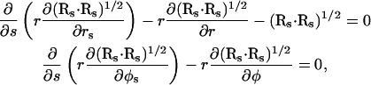 |
(A5) |
where the s subscript denotes differentiation with respect to s. Maximizing the volume leads to similar equations
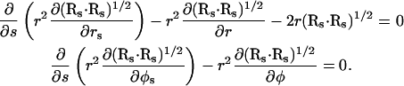 |
(A6) |
Combining the second equation from Eq. A5 with the second equation from Eq. A6 demands that  which simplifies these four equations to just one, such that
 |
(A7) |
This is the same as extremizing the length of the centerline of the cell body. Since the volume must be maximized, the length of the centerline must be maximized at a constant distance from the protein ribbon and the cell body should have a constant circular cross-section. Therefore, the protein ribbon will lie on the surface along the path of least distance, as is observed experimentally.
APPENDIX B: MODEL FOR HELICAL WAVE PROPAGATION IN SPIROPLASMA
We begin by working in a material frame, i.e., an orthonormal triad  where
where  lies along the tangent,
  points toward an imaginary line on the rod surface, and
  A strain vector,
  defines the rotation of this frame through the kinematic relation
 |
(B1) |
where s is the distance along the filament, Ω1 and Ω2 curvatures in the direction of  and
and  respectively, and Ω3 the twist per length along the filament.
We define a bend and twist energy as
 |
(B2) |
where A1 and A2 are bending moduli, and ξ is the chemical advancement coordinate discussed below. C is the twist modulus; Ω10, Ω20, and Ω30 are preferred curvatures and twist density, respectively, which are dependent on the chemical state; and Λ is a Lagrange multiplier which enforces inextensibility and acts like a tension. For problems with free ends, it is easier to work in an intrinsic frame and use a complex curvature and preferred curvature defined as
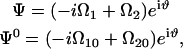 |
(B3) |
with  (Goldstein et al., 2000, 1998). The dynamics for this frame is
 |
(B4) |
with
 |
(B5) |
where Π is a complex velocity perpendicular to the filament tangent, ζ is a drag coefficient,  and we have dropped the 3 subscript from the twist density for simplicity. The dynamics for the twist density is
 |
(B6) |
with ζr a rotational drag coefficient. The constraint that  enforces inextensibility and sets Λ through the equation
 |
(B7) |
where  is the force per length which is found from the functional derivative of the energy and
  . We assume that both Ψ0 and Ω0 are functions of the chemical state similar to what was assumed for the one-dimensional compression waves:
 |
(B8) |
where κ0 and  define the maximum values of the preferred curvature and twist and α, β, γ, and δ are constants. Note that Ψ0 and Ω0 are out-of-phase. This is because, for a flexing helix, the maximum pitch is associated with the minimum radius of curvature and vice versa.
We model the chemical cycle as a periodic orbit on the circle, with coordinate ξ. We assume that the chemical reaction cycle has a stress-free rate ω0 that is modified by the local tension, Λ:
 |
(B9) |
where χ is the mechanochemical coupling parameter, chosen such that 
APPENDIX C: CALCULATION OF THE FORCE AND SWIMMING VELOCITY FOR SPIROPLASMA
The elastic force per length that acts on the filament is found from the functional derivative of the elastic energy with respect to the position,  giving
 |
(C1) |
where e, Φ, and Λ are as previously defined and
 |
(C2) |
This force per length can be shown to be a total derivative. Therefore, the total elastic force on the system is
 |
(C3) |
 |
With boundary condition such that  and
and  this simplifies to
 |
(C4) |
and if Λ(L) = 0, then 
To estimate the swimming speed for Spiroplasma, we use slender body hydrodynamics to calculate the fluid flow created by a helix flexing with a traveling pitch wave. For a slender body, the force per length, f, that acts on the body is
 |
(C5) |
where u = ∂r/∂t is the velocity of the body, and  is the tangent vector. ζ = 2πμ/(ln(L/2a) + c) and
  are the tangential and perpendicular drag coefficients calculated from slender body hydrodynamics (Keller and Rubinow, 1976) with L the length of the filament, a the radius, and c a constant of order unity. We will generally assume that the drags perpendicular and parallel to the filament are approximately equal.
For a free swimmer, the total force on the body is zero. Therefore,
 |
(C6) |
Using Eq. C5 in C6, and decomposing u into a disturbance motion, u′, and a translational velocity, U, we find
 |
(C7) |
We are interested in propulsion of helical bodies along the helix axis caused by traveling pitch waves. We define the position of a filament with a traveling pitch wave as
 |
(C8) |
where zm is the z-position of material points on the unperturbed filament, R is the radius of curvature, P is the unperturbed pitch of the helix, and ɛ is ≪1. Since we are interested in propulsion along the helix axis,  we dot
  into C7, and dividing by
  we get
 |
(C9) |
For simplicity, we set  and find
 |
(C10) |
From C8,
 |
(C11) |
Using Eq. C11 in C10, expanding to order ɛ2, and taking the time average, we find the average translational velocity along the helix axis
 |
(C12) |
We assume that k = 2πn/NP, with N the number of helical turns of the cell. For Spiroplasma, P ≈ 1 μm, R ≈ 0.2 μm, and R ≈ 2 μm (Trachtenberg and Gilad, 2001), which simplifies C12 to
 |
(C13) |
This implies that for a 5-μm-long bacterium with ɛ = 1/4, n = 2, and ω = 40 s−1 produces an average swimming speed of 1.2 μm/s. We could also have used that k = 2π/λ, where λ is the wavelength of the traveling wave. If we approximated this wavelength using elasticity theory, we find that
 |
(C14) |
Substituting this into C12 and using  where η is the viscosity, we find
 |
(C15) |
which implies that the translational velocity should increase with viscosity. Also, because the total force and torque on the swimming body are zero, the pitch wave will produce a rotation as well as a translational velocity. By requiring that the torque produced by the translating helix is zero, we find
 |
(C16) |
where Ω is the angular velocity about the z-axis.
APPENDIX D: NUMERICAL SOLUTION TO THE HELICAL FILAMENT EQUATIONS
To solve these equations, we time-step ΨR,I using a second-order Crank-Nicholson method, where the subscript R and I represent the real and imaginary parts, respectively,
 |
(D1) |
where  is the fourth derivative operator,
 |
(D2) |
and  is the symmetric third derivative operator,
  is the tridiagonal second derivative operator,
  is the symmetric first derivative operator, Λ is found from B7, and the integral is calculated discretely using the form for Π given in B5. Ω is solved for using
 |
(D3) |
with
 |
(D4) |
and
 |
(D5) |
We solve these equations with boundary conditions
 |
(D6) |
We use a normal Euler method to time-step the ξ equation,
 |
(D7) |
APPENDIX E: MODEL FOR THE GLIDING MOTOR OF M. MOBILE
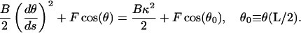
We characterize the force-generating element in the nose structure by two coordinates, X1 (tip), and X2 (neck) (See Fig. 6). The cell body is characterized by the coordinate X3, and elastically connected to the nose by the spring whose elastic constant is K. The force generated by the deformation of the elastic filament in the nose may be either a longitudinal shortening or a transverse bending. We investigate both possibilities by a corresponding redefinition of the nose-generated force.
FIGURE 6.

(a) Diagram of the experimental system. A bead is attached to the cell body and subject to a load force, Fload, from a fluid flow or laser trap. (b) The mechanical cycle of the model motor. (c) The phases of the mechanochemical cycle showing the relationship between the contracted/extended and detached/attached states.
FIGURE 7.

(a) Variables for the bending formula. (b) Projected length, Lp, versus dimensionless force,  .
.
For the bending model, we denote by κ the spontaneous curvature of the filament bundle. The value κ depends on the local chemical state, denoted by ξ, which changes with the progress of the chemical cycle (nucleotide hydrolysis and/or ionic environment). Therefore, the projected length of the filament, Lp = X1 − X2, is a function of ξ and the applied load force. According to Miyata and Uenoyama (2002), the gliding motion of mycoplasma is correlated with its ability to attach to the substrate via the attachment organelle at the tip of nose structure. Propulsion is possible if the attachment-detachment cycle is correlated with the extension-contraction cycle.
The equation of motion for the bacteria body can be described by the force balance equation, Eq. 3, with 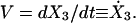 We model the forces as follows. The elastic force on the cell body from its attachment to the force-generating nose, Fel, is a harmonic spring force:
 |
(E1) |
where K is the elastic constant of the spring and L0 is its rest length. The friction force, Ffr, due to adhesion of the body to the substrate, is a combination of effective viscous friction, ζeff (liquid friction), and solid friction, with a yield force Fyield. Mathematically we describe it as follows:
 |
(E2) |
Equation 3 becomes:
 |
(E3) |
where  , and H(x) is the Heaviside step function: H(x > 0) = 1, H(x < 0) = 0.
We also assume that the drag-on-the-nose is much smaller than on the body so that it is always in mechanical equilibrium. If the tip of the nose is attached (denoted by ON = 1), then the position of the neck is determined by the balance of the elastic force from the body spring, Fel, and the force generated by the filament:
 |
(E4) |
 is the force-extension relation between the projection length of the elastic filament Lp and the force applied at its end,
  . In Appendix F we show how to obtain this relation for the bending of the filament with a preferred curvature κ. For longitudinal shortening model, we assume
 |
(E5) |
where Lb is an equilibrium length of the bundle that is a function of chemical state and Kb is a spring constant.
After detachment of the tip (denoted by ON = 0), both the elastic neck connection and the filament quickly relax to their equilibrium configurations:
 |
(E6) |
where  is the equilibrium projection length of a filament with curvature κ, obtained from the equation
  for bending (see Appendix F) or
  for contraction.
Since the length of the filament is <1 μm, we assume that stress propagates along the filament fast enough to synchronize the chemical cycle along its entire length; e.g., ξ does not depend on the x-coordinate. The chemical cycle is periodic, and so we use a simplified description by mapping the cycle onto a circle
 |
(E7) |
where f is a frequency of chemical cycle. We couple the reaction to the bending of the elastic filament by assuming that the preferred curvature is a step function of the reaction advancement, ξ (see Fig. 6 c):
 |
(E8) |
That is, for 0 < ξ < ξ1, the preferred curvature is increased by κ1, shortening the projected length of the filament. For the contraction model, we assume
 |
(E9) |
That is, for 0 < ξ < ξ1, the preferred length is shortened from L to Ls.
If the attachment and detachment of the tip is synchronized with the cycle in such a way that the tip attaches before contraction and detaches before extension, then periodic changes in the projection length of the filament will drive propulsion (Fig. 6 c):
 |
(E10) |
Here ON = 0 if the tip is detached, and ON = 1 if it is attached. As illustrated in Fig. 6 c, we assume that  . Alternatively one can introduce chemical kinetics equations for the attachment/detachment of the tip and make the rates functions of the chemical states. The results (not shown) are very similar to the simple step-function approximation Eq. E10.
To fit the data of Miyata et al. (2002) we computed the model with the parameters summarized in Table 1. The results are shown on Fig. 2, c and d.
TABLE 1.
Parameter values used in the simulation of Mycoplasma mobile gliding
| Bending model
|
Contraction model
|
|||||
|---|---|---|---|---|---|---|
| Parameter | Notation | No-slip | Back-slip | No-slip | Back-slip | |
| Drag coefficient | ζ | 0.5 pN s/μm | 0.63 pN s/μm | 0.63 pN s/μm | 0.63 pN s/μm | |
| Spring elastic constant | K | 1250 pN/μm | 1562 pN/μm | 1562 pN/μm | 1562 pN/μm | |
| Bundle elastic constant | Kb | N/A | N/A | 1250 pN/μm | 1250 pN/μm | |
| Bending module | B | 0.25 pN μm2 | 0.25 pN μm2 | N/A | N/A | |
| Spring rest length | L0 | 0.2 μm | 0.2 μm | 0.2 μm | 0.2 μm | |
| Solid friction force | Fyield | 26 pN | 8 pN | 26 pN | 8 pN | |
| Chemical cycle frequency | 22.5° | f | 185 s−1 | 85 s−1 | 150 s−1 | 150 s−1 |
| 27.5° | 280 s−1 | 125 s−1 | 220 s−1 | 220 s−1 | ||
| Filament length | L | 0.4 μm | 0.4 μm | 0.4 μm | 0.4 μm | |
| Spontaneous curvature | κ0 | 0.01 μm−1 | 0.01 μm−1 | N/A | N/A | |
| Spontaneous curvature | κ1 | 3.92 μm−1 | 3.92 μm−1 | N/A | N/A | |
| Preferred length | Ls | N/A | N/A | 0.37 μm | 0.38 μm | |
| Beginning of extension phase | ξ1 | 3π /2 | 3π /2 | 3π /2 | 3π /2 | |
| Beginning of detachment phase | 22.5°C | ξ2 | 3π/2 − 0.29 | 3π/2 − 0.13 | 3π/2 − 0.185 | 3π/2 − 0.27 |
| 27.5°C | 3π/2 − 0.44 | 3π/2 − 0.20 | 3π/2 − 0.27 | 3π/2 − 0.27 | ||
| End of detachment phase | 22.5°C | ξ3 | 3π/2 + 0.29 | 3π/2 + 0.13 | 3π/2 + 0.185 | 3π/2 − 0.27 |
| 27.5°C | 3π/2 +0.44 | 3π/2 + 0.20 | 3π/2 + 0.27 | 3π/2 − 0.27 | ||
Drag coefficient on the attached bead can be estimated as in Miyata et al. (2002): 1.6 × 6π × (rbead) ∼ 0.065 pNs/μm. We chose to scale this drag coefficient by a factor of 8–10 to account for the interaction of the body with the substrate, i.e., the effective drag. To estimate effective spring constants for a filament bundle we use measurements for collagen fibers which show linear-force extension relations for small forces F/A ∼ k0 ΔL/L with k0 ∼ 1000 N/cm2 = 107 pN/μm2 (Rubin et al., 1969; Yonath et al., 1965). Assuming cross-section area of 50–100 nm2 and L ∼ 0.5 μm, one can estimate K ∼ 1000–2000 pN/μm. The bending modulus is B = πR4E/4. Assuming a single filament with a bending modulus the same as actin, E ∼ 5 × 10⁹N/m2 = 5 × 10⁹pN/μm2, and with a radius of 3 nm, we obtain B ∼ 0.25 pN/μm2.
To fit the data at two different temperatures one must scale the cycle frequency, f. To produce curves with the same stall force for the back-slip model we had to assume that time of back-slipping (the nose is detached), (ξ3 − ξ2)/f, does not depend on temperature, i.e., temperature-dependence is in the step corresponding to attached state of the nose. To address the dependence of gliding velocity on temperature, one has to make a more detailed model of the chemical cycle controlling bending/attachment cycle. We hypothesize that the frequency is determined by a membrane pacemaker so that periodic changes in the local ionic environment in the nose initiate the bending directly on the ATPase cycle.
APPENDIX F: FORCE-EXTENSION RELATION FOR A BENT FILAMENT
The following equation determines the shape of the rod, subject to a force  (see Fig. 7 a). (Landau and Lifshitz, 1995):
 |
(F1) |
where the bending modulus B is the product of the Young's modulus and the moment of inertia, θ(s) is the slope of the rod, and −L/2 ≤ s ≤ L/2 is the arc length. Symmetry determines the boundary condition θ(0) = 0. To solve Eq. 1 for 0 ≤ s ≤ L/2, a first integration of F1 gives
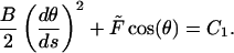 |
(F2) |
At s = L/2 the end is free, and therefore the curvature,  , is equal to the spontaneous curvature, κ. Thus
 |
(F3) |
Since the contour arc length is constant, θ0 is determined by the condition
 |
(F4) |
where the dimensionless force Φ = 2 The projection length, Lp, is defined as
 |
(F5) |
Solving F4 and F5 simultaneously gives the relation between the applied force and the projection length. At zero force, e.g., when the nose tip is detached:
 |
(F6) |
APPENDIX G: EXAMPLE OF A MECHANOCHEMICAL OSCILLATOR
The ubiquity of mechanosensitive ion channels in bacteria (Hamill and Martinac, 2001) suggests that contraction of mechanochemical filaments can couple to ion fluxes to create a mechanochemical oscillator. Here we give an example to show how this can come about. Let us suppose that a filament at standard ionic conditions is bistable with two stable states, L = L1 and L = L2, and one unstable state, L = L3, so that L1 > L3 > L2. The dynamics of the filament is generically modeled by
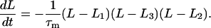 |
(G1) |
Here τm is a mechanical relaxation timescale. As the ionic concentration changes, one of the states becomes favorable relative to the other:
 |
(G2) |
That means that at high ionic concentrations (c > c0) only the shorter state exists, whereas at c < c0 only the longer state exists. To make a feedback loop, we assume that elongation of the filament elastically distorts the membrane and opens a stretch-activated channel that increases c:
 |
(G3) |
where we have modeled the channel kinetics as a Hill function with amplitude S. To reduce the number of parameters we have scaled Eqs. G2 and G3 so that c0 = 1 and L3 = 0.5. Solving Eqs. G2 and G3 with the parameters summarized in Table 2 one can obtain the oscillatory solution shown in Fig. 8. Furthermore, such a model will have weaker temperature-dependence than an oscillator membrane built around an excitable membrane (e.g., Hodgkin-Huxley) since the mechanical time constant, τm, will depend only linearly on temperature, whereas the chemical time constant, τc, will have exponential (Boltzmann) dependence.
FIGURE 8.

A mechanochemical oscillator. (a) The (L, c) phase plane showing the shape of the nullclines and the limit cycle. (b) Enlargement of the limit cycle in the phase plane and (c) time plot.
TABLE 2.
Parameters for mechanochemical oscillator model
| Parameter | Notation | Value |
|---|---|---|
| Shorter equilibrium length | L2 | 0.3 |
| Longer equilibrium length | L1 | 0.75 |
| Mechanochemical coupling | α | 0.25 |
| Mechanical timescale | τm | 0.0001 s |
| Chemical timescale | τc | 0.003 s |
| Source term | S | 3 |
| Exponent | Q | 8 |
References
- Ajdari, A., and H. A. Stone. 1999. A note on swimming using internally generated traveling waves. Phys. Fluids. 11:1275–1277. [Google Scholar]
- Barboiu, M., and J.-M. Lehn. 2002. Dynamic chemical devices: modulation of contraction/extension molecular motion by coupled-ion binding/pH change-induced structural switching. Proc. Natl. Acad. Sci. USA. 99:5201–5206. [DOI] [PMC free article] [PubMed] [Google Scholar]
- Bass, R., P. Strop, M. Barclay, and D. Rees. 2002. Crystal structure of Escherichia coli MscS, a voltage-modulated and mechanosensitive channel. Science. 298:1582–1587. [DOI] [PubMed] [Google Scholar]
- Ben-Yehuda, S., and R. Losick. 2002. Asymmetric cell division in B. subtilis involves a spiral-like intermediate of the cytokinetic protein FtsZ. Cell. 109:257–266. [DOI] [PubMed] [Google Scholar]
- Beven, L., and H. Wroblewski. 1997. Effect of natural amphipathic peptides on viability, membrane potential, cell shape and motility of mollicutes. Res. Microbiol. 148:163–175. [DOI] [PubMed] [Google Scholar]
- Bottino, D., A. Mogilner, T. Roberts, M. Stewart, and G. Oster. 2002. How nematode sperm crawl. J. Cell Sci. 115:367–384. [DOI] [PubMed] [Google Scholar]
- Burchard, A. C., R. P. Burchard, and J. A. Kloetzel. 1977. Intracellular, periodic structures in the gliding bacterium Myxococcus xanthus. J. Bacteriol. 132:666–672. [DOI] [PMC free article] [PubMed] [Google Scholar]
- Calladine, C. R. 1975. Construction of bacterial flagella. Nature. 225:121–124. [DOI] [PubMed] [Google Scholar]
- Camalet, S., F. Julicher, and J. Prost. 1999. Self-organized beating and swimming of internally driven filaments. Phys. Rev. Lett. 82:1590–1593. [Google Scholar]
- Clark, R., and J. Cowey. 1958. Factors controlling the change of shape of certain Nemertean and Turbellian worms. J. Exp. Biol. 35:731–748. [Google Scholar]
- Coombs, D., G. Huber, J. Kessler, and R. Goldstein. 2002. Periodic chirality transformations propagating on bacterial flagella. Phys. Rev. Lett. 89:118101–118104. [DOI] [PubMed] [Google Scholar]
- Daniels, M. J., J. M. Longland, and J. Gilbart. 1980. Aspects of motility and chemotaxis in spiroplasmas. J. Gen. Microbiol. 118:429–436. [Google Scholar]
- Davis, R. E. 1979. Spiroplasmas: newly recognized anthropod-borne pathogens. In Leafhopper Vectors and Plant Disease Agents. K. F. Harris, editor. Academic Press, New York. pp.451–484.
- Dimroth, P., H. Wang, M. Grabe, and G. Oster. 1999. Energy transduction in the sodium F-ATPase of Propionigenium modestum. Proc. Natl. Acad. Sci. USA. 96:4924–4929. [DOI] [PMC free article] [PubMed] [Google Scholar]
- Ehlers, K. M., A. D. T. Samuel, H. C. Berg, and R. Montgomery. 1996. Do cyanobacteria swim using traveling surface waves? Proc. Natl. Acad. Sci. USA. 93:8340–8343. [DOI] [PMC free article] [PubMed] [Google Scholar]
- Freese, A., H. Reichenbach, and H. Lunsdorf. 1997. Further characterization and in situ localization of chain-like aggregates of the gliding bacteria Myxococcus fulvus and Myxococcus xanthus. J. Bacteriol. 179:1246–1252. [DOI] [PMC free article] [PubMed] [Google Scholar]
- Gilad, R., P. Porat, and S. Trachtenberg. 2003. Motility modes of Spiroplasma melliferum BC3: a helical, wall-less bacterium driven by a linear motor. Mol. Microbiol. 47:657–669. [DOI] [PubMed] [Google Scholar]
- Goldstein, R. E., A. Goriely, G. Huber, and C. W. Wolgemuth. 2000. Bi-stable helices. Phys. Rev. Lett. 84:1631–1634. [DOI] [PubMed] [Google Scholar]
- Goldstein, R. E., T. R. Powers, and C. H. Wiggins. 1998. Viscous nonlinear dynamics of twist and writhe. Phys. Rev. Lett. 80:5232–5235. [Google Scholar]
- Hamill, O., and B. Martinac. 2001. Molecular basis of mechanotransduction in living cells. Physiol. Rev. 81:685–740. [DOI] [PubMed] [Google Scholar]
- Hotani, H. 1982. Micro-video study of moving bacterial flagellar filaments. J. Mol. Biol. 156:791–806. [DOI] [PubMed] [Google Scholar]
- Joanny, J., F. Jülicher, and J. Prost. 2003. Motion of an adhesive gel in a swelling gradient: a mechanism for cell locomotion. Phys. Rev. Lett. 90:168102. [DOI] [PubMed] [Google Scholar]
- Jones, L., R. Carballido-López, and J. Errington. 2001. Control of cell shape in bacteria: helical, actin-like filaments in Bacillus subtilis. Cell. 104:913–922. [DOI] [PubMed] [Google Scholar]
- Kaiser, D. 2000. Bacterial motility: how do pili pull? Curr. Biol. 10:R777–R780. [DOI] [PubMed] [Google Scholar]
- Keller, J. B., and S. I. Rubinow. 1976. Slender body theory for slow viscous flow. J. Fluid Mech. 75:705–714. [Google Scholar]
- Koehl, M., K. Quillin, and C. Pell. 2000. Mechanical design of fiber-wound hydraulic skeletons: the stiffening and straightening of embryonic notochords. Am. Zool. 40:28–41. [Google Scholar]
- Landau, L., and E. Lifshitz. 1995. The Theory of Elasticity. Butterworth-Heinemann, Boston.
- Lowe, J., and L. A. Amos. 1998. Crystal structure of the bacterial cell-division protein FtsZ. Nature. 391:203–206. [DOI] [PubMed] [Google Scholar]
- Lunsdorf, H., and H. Reichenbach. 1989. Ultrastructural details of the apparatus of gliding motility of Myxococcus fulvus (myxobacterales). J. Gen. Microbiol. 135:1633–1641. [Google Scholar]
- Lunsdorf, H., and H. U. Schairer. 2001. Frozen motion of gliding bacteria outlines inherent features of the motility apparatus. Microbiol. UK. 147:939–947. [DOI] [PubMed] [Google Scholar]
- Macnab, R. M., and M. K. Ornston. 1977. Normal-to-curly flagellar transitions and their role in bacterial tumbling—stabilization of an alternative quaternary structure by mechanical force. J. Mol. Biol. 112:1–30. [DOI] [PubMed] [Google Scholar]
- Mahadevan, L., and P. Matsudaira. 2000. Motility powered by supramolecular springs and ratchets. Science. 288:95–99. [DOI] [PubMed] [Google Scholar]
- Mayer, F. 2003. Cytoskeletons in prokaryotes. Cell Biol. Int. 27:429–438. [DOI] [PubMed] [Google Scholar]
- Mcbride, M. 2001. Bacterial gliding motility: multiple mechanisms for cell movement. Am. Rev. Microbiol. 55:49–75. [DOI] [PubMed] [Google Scholar]
- Miyata, M., W. Ryu, and H. Berg. 2002. Force and velocity of Mycoplasma mobile gliding. J. Bacteriol. 184:1827–1831. [DOI] [PMC free article] [PubMed] [Google Scholar]
- Miyata, M., and A. Uenoyama. 2002. Movement on the cell surface of the gliding bacterium, Mycoplasma mobile, is limited to its head-like structure. FEMS Microbiol. Lett. 215:285–289. [DOI] [PubMed] [Google Scholar]
- Moriyama, Y., H. Okamoto, and H. Asai. 1999. Rubber-like elasticity and volume changes in the isolated spasmoneme of giant Zoothamnium sp. under Ca2+-induced contraction. Biophys. J. 76:993–1000. [DOI] [PMC free article] [PubMed] [Google Scholar]
- Namba, K., and F. Vonderviszt. 1997. Molecular architecture of bacterial flagellum. Q. Rev. Biophys. 30:1–65. [DOI] [PubMed] [Google Scholar]
- Nguyen, T., W. Chin, and P. Verdugo. 1998. Role of Ca2+/K+ ion exchange in intracellular storage and release of Ca2+. Nature. 395:908–912. [DOI] [PubMed] [Google Scholar]
- Oster, G., and H. Wang. 2003. Rotary protein motors. Trends Cell Biol. 13:114–121. [DOI] [PubMed] [Google Scholar]
- Perozo, E., D. Cortes, P. Sompornplsut, A. Kloda, and B. Martinac. 2002a. Open channel structure of MscL and the gating mechanism of mechanosensitive channels. Nature. 418:942–948. [DOI] [PubMed] [Google Scholar]
- Perozo, E., A. Kloda, D. Cortes, P. Sompornplsut, and B. Martinac. 2002b. Physical principles underlying the transduction of bilayer deformation forces during mechanosensitive channel gating. Nat. Struct. Biol. 9:696–703. [DOI] [PubMed] [Google Scholar]
- Purcell, E. 1977. Life at low Reynolds number. Am. J. Physics. 45:3–11. [Google Scholar]
- Rubin, M. M., A. P. Karl, and A. Katchalsky. 1969. Equilibrium mechanochemistry of collagen fibers. Biochemistry. 8:3628–3637. [DOI] [PubMed] [Google Scholar]
- Samatey, F. A., K. Imada, S. Nagashima, F. Vonderviszt, T. Kumasaka, M. Yamamoto, and K. Namba. 2001. Structure of the bacterial flagellar protofilament and implications for a switch for supercoiling. Nature. 410:331–337. [DOI] [PubMed] [Google Scholar]
- Samuel, A., J. Petersen, and T. Reese. 2001. Envelope structure of Synechococcus sp. WH8113, a nonflagellated swimming cyanobacterium. BMC Microbiol. 1:4. [DOI] [PMC free article] [PubMed] [Google Scholar]
- Seto, S., and M. Miyata. 2003. Attachment organelle formation represented by localization of cytadherence protein and formation of electron-dense core in the wild-type and mutant strains of Mycoplasma pneumoniae. J. Bacteriol. 185:1082–1091. [DOI] [PMC free article] [PubMed] [Google Scholar]
- Shimizu, T., and M. Miyata. 2002. Electron microscopic studies of three gliding mycoplasmas, Mycoplasma mobile, M. pneumoniae, and M. gallisepticum, by using the freeze-substitution technique. Curr. Microbiol. 44:431–434. [DOI] [PubMed] [Google Scholar]
- Siddiqui, A. M., R. P. Burchard, and W. H. Schwarz. 2001. An undulating surface model for the motility of bacteria gliding on a layer of non-Newtonian slime. Intl. J. Non-Linear Mech. 36:743–761. [Google Scholar]
- Steinberg, I., A. Oplatka, and A. Katchalsky. 1966. Mechanochemical engines. Nature. 210:568–571. [Google Scholar]
- Stone, H., and A. Samuel. 1996. Propulsion of microorganisms by surface distortions. Phys. Rev. Lett. 77:4102–4104. [DOI] [PubMed] [Google Scholar]
- Sun, H., Z. Yang, and W. Shi. 1999. Effect of cellular filamentation on adventurous and social gliding motility of Myxococcus xanthus. Proc. Natl. Acad. Sci. USA. 96:15178–15183. [DOI] [PMC free article] [PubMed] [Google Scholar]
- Sussman, M. V., and A. Katchalsky. 1969. Mechanochemical turbine: a new power cycle. Science. 167:45–47. [DOI] [PubMed] [Google Scholar]
- Tawada, K., and K. Sekimoto. 1991. Protein friction exerted by motor enzymes through a weak binding interaction. J. Theor. Biol. 150:193–200. [DOI] [PubMed] [Google Scholar]
- Trachtenberg, S. 1998. Mollicutes-wall-less bacteria with internal cytoskeletons. J. Struct. Biol. 124:244–256. [DOI] [PubMed] [Google Scholar]
- Trachtenberg, S., and R. Gilad. 2001. A bacterial linear motor: cellular and molecular organization of the contractile cytoskeleton of the helical bacterium Spiroplasma melliferum BC3. Mol. Microbiol. 41:827–848. [DOI] [PubMed] [Google Scholar]
- Verdugo, P. 1991. Mucin exocytosis. Am. Rev. Respir. Dis. 144:533–537. [DOI] [PubMed] [Google Scholar]
- Verdugo, P., M. Aitken, L. Langley, and M. J. Villalon. 1987a. Molecular mechanism of product storage and release in mucin secretion. II. The role of extracellular Ca++. Biorheology. 24:625–633. [DOI] [PubMed] [Google Scholar]
- Verdugo, P., I. Deyrup-Olsen, M. Aitken, M. Villalon, and D. Johnson. 1987b. Molecular mechanism of mucin secretion. I. The role of intragranular charge shielding. J. Dent. Res. 66:506–508. [DOI] [PubMed] [Google Scholar]
- Willey, J., J. Waterbury, and E. Greenberg. 1987. Sodium-coupled motility in a swimming cyanobacterium. J. Bacteriol. 169:3429–3434. [DOI] [PMC free article] [PubMed] [Google Scholar]
- Wolgemuth, C., E. Hoiczyk, D. Kaiser, and G. Oster. 2002. How myxobacteria glide. Curr. Biol. 12:369–377. [DOI] [PubMed] [Google Scholar]
- Wolgemuth, C., A. Mogilner, and G. Oster. 2003. The hydration dynamics of polyelectrolyte gels with applications to cell motility and drug delivery. Eur. Biophys. J. In press. [DOI] [PubMed]
- Yonath, J., A. Oplatka, and A. Katchalsky. 1965. Equilibrium mechanochemistry of collagen fibres. In Structure and Function of Connective and Skeletal Tissue. Butterworths, London. pp.381–387.
Associated Data
This section collects any data citations, data availability statements, or supplementary materials included in this article.