

Abstract
Advances in biotechnology and computer science are providing the possibility to construct mathematical models for complex biological networks and systematically understand their properties. Traditional network identification approaches, however, cannot accurately recover the model parameters from the noisy laboratory measurements. This article introduces the concept of optimal identification (OI), which utilizes a global inversion algorithm to extract the full distribution of parameters consistent with the laboratory data. In addition, OI integrates suitable computational algorithms with experimental capabilities in a closed loop fashion to maximally reduce the breadth of the extracted parameter distribution. The closed loop OI procedure seeks out the optimal set of control chemical fluxes and data observations that actively filter out experimental noise and enhance the sensitivity to the desired parameters. In this fashion, the highest quality network parameters can be attained from inverting the tailored laboratory data. The operation of OI is illustrated by identifying a simulated tRNA proofreading mechanism, in which OI provides superior solutions for all the rate constants compared with suboptimal and nonoptimal methods.
INTRODUCTION
Mathematical modeling and computer simulation have long been recognized as important approaches in studying many aspects of biology (Bower, 2001; Murray, 2002). Over the last decade, advances in biotechnology and computer science have made these tools increasingly useful in investigating complex biomolecular systems, including gene regulatory networks (McAdams and Arkin, 1998; Smolen et al., 2000; Hasty et al., 2001; Jong, 2002), metabolic systems (Mendes and Kell, 1998; Bailey, 1998; Giersch, 2000; Covert et al., 2001), signal transduction pathways (Endy and Brent, 2001; Hoffmann et al., 2002), and neural networks (Dayan and Abbott, 2001). The resultant models of these processes can be qualitative or quantitative. The qualitative models usually describe the connectivities and regulatory relationships among the biosystem components in simple graphical forms, whereas the quantitative models contain more information such as detailed reaction mechanisms and associated parameters. In this article, we address relevant issues in identifying quantitative models at the molecular level, although similar logic would also apply to models at other levels.
In constructing a quantitative biosystem model, the form of the mathematical equations are first established on physical and biological grounds, as well as through previous knowledge about the system. To determine the system parameters from laboratory data, it is often necessary to introduce specific disturbances (e.g., chemical fluxes) to induce transient responses. The resultant typically temporal responses of some suitable biomolecular components are then recorded and the desired model parameters (e.g., reaction rate constants, diffusion coefficients, binding affinities, etc.) are extracted by inverting the laboratory data. Various issues need to be considered in extracting these parameters, including data noise, the limited amount of laboratory data, as well as the nonlinearity of most models. These issues dictate that generally a distribution of parameters will exist where each set of parameters in the distribution reproduces the laboratory data to within its error range. However, most current inversion methods provide only one or a small set of parameters and subsequently unreliable model predictions.
In this article, we propose a general optimal identification (OI) procedure for finding the best attainable model parameters. Unlike traditional identification methods, OI aims at recovering the full family of parameter values consistent with the laboratory data. Most importantly, OI integrates various computational algorithms with the experimental capabilities, which operate together in a closed-loop fashion to efficiently reduce the breadth of distribution for the extracted parameter family. OI is achieved by the closed-loop operations aiming to determine the optimal laboratory controls (e.g., external chemical fluxes) and observations for obtaining the best quality system parameters. In this fashion, the parameter values can be extracted with minimum uncertainty. The “Optimal identification algorithm” section describes the general OI operations. The capability of OI is compared with nonoptimal and suboptimal methods in the “Illustration” section in a simulated identification of a tRNA proofreading mechanism. The conclusions are presented in the “Conclusion” section.
THE OPTIMAL IDENTIFICATION ALGORITHM
OI is rooted in the general concepts of closed-loop control (Brogan, 1985; Judson and Rabitz, 1992). In the sciences, the concepts and techniques of closed-loop control have been employed to achieve desired states or properties of the various systems, such as to alter chemical reaction processes (Assion et al., 1998), to selectively rearrange covalent bonds (Levis et al., 2001), to manipulate quantum system behavior (Rabitz et al., 2000; Bartels et al., 2000; Weinacht et al., 1999), to optimize semiconductor properties (Kunde et al., 2000), and recently to design/optimize molecular or system behavior in a number of areas in biology (Yokobayashi et al., 2002; Mayer and Arnold, 2002; Csete and Doyle, 2002; Yi et al., 2000; Ku et al., 2004). Identifying system parameters in a closed-loop fashion has also been studied, but mostly concerning linear systems in nonbiological areas and using gradient based methods (Ljung, 1999; Walter et al., 1997). OI instead identifies the model parameter distribution in a global and nonlinear fashion, and it utilizes a nonlinear learning algorithm to guide the choice of iterative controls so that the most accurate system information (e.g., the best model parameter values characterized as having the narrowest error distribution) can be extracted from a minimum number of experiments. OI has shown the capability of being highly effective in inverting quantum-mechanical observations (Geremia and Rabitz, 2002, 2003), and this article explores its applicability in biomolecular system identifications.
Fig. 1 shows the general components forming the OI procedure for identifying bionetwork model parameters. There are three basic components: the analysis module, the control module, and the inversion module. To initiate operations, a proposed model is examined in the analysis module to estimate: a), the best biomolecular species for monitoring the network behavior, and b), the best biomolecular fluxes for controlling (disrupting) the system. Based on these initial analysis results, a number of trial controls are applied in the laboratory and the biosystem's temporal responses are recorded. The inversion module then extracts the full family of model parameters that quantitatively reproduce the system's behavior in each trial control experiment within the reported or estimated laboratory errors, and the “quality” of the parameter family is specified by the distribution of consistent parameters. The parameter distribution is very likely not Gaussian or symmetric due to the typically highly nonlinear relationship between the laboratory data and the system parameters. Some measure of the distribution breadth (e.g., its combined left and right half widths) needs to be chosen as the “cost” associated with each trial control. In real applications, the laboratory constraints on the accessible controls and observations can also be included in the cost function. The control loop is closed by feeding the cost back to the control module to determine the next generation of trial controls, aiming to further reduce the breadth of the distribution. This iterative process continues until the best inversion quality (i.e., the narrowest parameter distribution) is obtained for all the parameters. The remainder of this section presents the detailed operations in each module of the OI “machine” in Fig. 1.
FIGURE 1.

General OI operational procedure for identifying bionetwork model parameters. The proposed mechanism and previous knowledge of the biosystem is provided for the analysis module, which estimates the biomolecular species for controlling the system (xc) and recording the responses (xr). In the control module, time-dependent trial controls uc(t) are applied and the system's behavior Xr(t) is measured. The inversion module extracts the full distribution of parameters k consistent with the laboratory data and calculates its inversion quality Qinv, which is then returned to the learning algorithm in the control module to calculate the control cost Jctrl for selecting new experiments, with the purpose of achieving better inversion quality. This iterative operation continues until the best attainable quality is achieved for all the model parameters under any laboratory constraints R(u, X). Occasionally, the laboratory data and the extracted parameter distributions may be fed back to the analysis module to update the choices of controls xc and observations xr.
The analysis module
An important property of many biomolecular systems is their robustness to both internal variations (e.g., most random gene mutations) and external disturbances (e.g., environmental changes). This property implies that arbitrary control perturbations to a biosystem may result in a minimal response in many of its molecular components. Thus, if the OI experiments are not appropriately designed, it is very likely that little information of value can be recovered from the experimental measurements for identifying the model parameters. Most current biosystem identification methods use experience, intuition, or simple analyses to select the biomolecular species for controls and those for recording the system's response. This rather heuristic approach is unsatisfactory for biosystems with complex architectures, whose behavior is very hard to anticipate in this fashion. In OI, the analysis module is introduced to provide the best estimate of how to disturb and observe the biosystem with the identification goal in mind. The module employs various system dependent sensitivity analysis algorithms utilizing available semiquantitative or qualitative information about the system. The analysis module may be revisited a number of times during OI operations to sharpen up the estimates as the distribution of parameters improves. The module would also consider all relevant ancillary information including restrictions on utilizing particular controls, species detection capabilities, anticipated data errors, and any prior limitations on biosystem response behavior (e.g., toxic response limits).
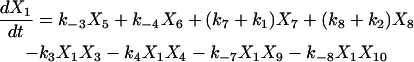
Using a biochemical reaction network as an example, consider a system containing N species x = (x1, x2,…, xN) and M unknown reaction rate constants k = (k1, k2,…, kM) with its dynamic behavior described by N ordinary differential equations (ODEs).
 |
(1) |
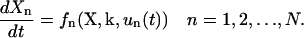
In Eq. 1, Xn is the concentration of xn, un(t) is the time-dependent external control associated with xn, such as a chemical flux of xn or an influx of other molecules that selectively regulate the activity of xn. This work utilizes a model of this form, but other types of models (e.g., stochastic, spatiotemporal, etc.) may be employed depending on the nature of the biosystem. Given this mechanistic model, the analysis module serves to estimate: a), the sensitivities of all the concentrations X with respect to variations in the unknown rate constants k, and b), the sensitivities of the concentrations X with respect to the possible controls u(t). Different approaches may be used to calculate these sensitivities depending on the particular circumstances. In this work, the RS-HDMR (Random Sampling—High Dimensional Model Representation) algorithm (G. Li et al., 2001, 2002) is used for the analysis in a, and a simple method is employed for the analysis in b.
The RS-HDMR algorithm is a global sensitivity analysis technique that can decompose the total sensitivities into first, second, and higher-order terms. The notion of order refers to number of rate constants interacting, likely in a nonlinear fashion, contributing to the members of X. Calculations by RS-HDMR require at least an initial estimate of the following: the mechanistic model, the steady-state concentrations X* (to be used as initial values for ODE integrations), and the dynamic range  for each rate constant km. All these estimates often are either readily available or can be established from a few experiments in many real applications.
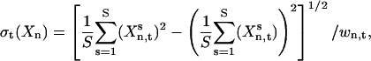
To estimate the general sensitivity of Xn to k, normally several thousand sets of randomly chosen rate constants ks(s = 1, 2 ,…, S) are generated over the range  . The temporal concentration profile of the system is then obtained for each ks by integrating the ODEs, and the total sensitivity σt(Xn) of Xn at time t is calculated as a relative standard deviation
 |
(2) |
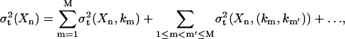
where  is the concentration of xn at time t for sample s, and wn,t is a weight factor that normalizes the absolute standard deviation of Xn,t. The total sensitivity σt(Xn) is decomposed into a set of contributions,
 |
(3) |
where the first-order term σt(Xn, km) represents the effect that the single independent variable km has on Xn, and the second-order term σt(Xn, (km, km′)) reflects the cooperative influence of km and km′ on Xn, etc. The details of the decomposition are discussed elsewhere (G. Li et al., 2001, 2002).
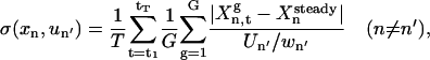
The sensitivity of Xn with respect to un′ is estimated by applying simulated constant influxes of un′ to the system. G random samples (usually a few hundred) of the unidentified parameters kg(g = 1, 2,…, G) are generated for averaging purposes, and the normalized sensitivity is calculated by
 |
(4) |
where  is the steady-state concentration of xn, Un′ is the magnitude of flux un′, and wn′ is a normalization factor. Time-dependent fluxes (instead of constant fluxes) will be used later in the control experiments, and this analysis serves as a quick estimate of the sensitivity to the possible controls.
Guided by the sensitivity values in Eqs. 3 and 4, respectively, a selection can be made for a subset xr ∈ x for recording the system's response, as well as another subset of xc ∈ x to serve as external controls. In general, xr should include biochemicals that are the most sensitive to variations in the unidentified rate constants k, and xc should include species whose influxes or controlled regulations can lead to the highest variations in the concentrations or activities of xr. Choosing the most sensitive species corresponds to most effectively disturbing the system and recording its most informative biomolecular behavior, in order for the experiments to be best utilized for extracting the model parameters. In practice, other factors such as experimental feasibility, cost, and precision also need to be taken into account.
The control module
Although the analysis module provides the current best estimate of the molecular species to serve as biosystem controls and other species chosen for concentration measurements, it is still impossible to predetermine the detailed temporal forms of the controls that can provide maximum system information and most effectively filter out the influence of the laboratory data noise. A learning algorithm is therefore introduced into the OI control module to integrate together the control experiments and the inversion module in a closed-loop fashion (see Fig. 1) to efficiently home in on the optimal control(s) to reveal the highest-quality solutions for the unknown model parameters. The learning algorithm operates in a pattern recognition role, and in this work, a genetic algorithm (GA) (Goldberg, 1989; Wall, 1995) is selected for optimizing the controls. A GA is used because: a), it can deal with complex, nonlinear problems; b), it can work well even when little information is available about the detailed operations of the system; and c), unlike most other algorithms, a GA can provide the global searching capability to avoid being trapped in local minima.
In the first excursion around the OI loop (Fig. 1), a set of I trial controls (
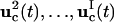 ) is applied in the laboratory to the selected biochemicals xc, and the responses of the system are recorded by measuring the concentrations of the species xr at multiple time points. In practice, the controls may be expressed in terms of vector control parameters a. Therefore, optimizing the control function corresponds to optimizing its control parameters. For the ith trial control
  the information about the control flux or its parameters and the concentration profiles
  is forwarded to the inversion module, which returns the inversion quality
  representing the 1/breadth of the distribution for the extracted rate constant family (see “The inversion module” section, Eqs. 7 and 8). The inversion quality can be used as the cost function
  for the control GA, which compares
  for all the controls and selects a certain percentage with the best cost to generate the next set of I trial controls by crossover and mutation operations (Goldberg, 1989; Wall, 1995). This iterative optimization process continues until one or a few controls are found to achieve an optimal reduction of the distribution breadth for all the parameters.
In real applications, the learning algorithm also needs to take into account the laboratory constraints, such as the difficulty of carrying out certain forms of experiments. A term representing laboratory constraints and other application-specific requirements can be used together with the inversion quality to yield the total control cost,
 |
(5) |
Here 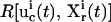 is a positive functional representing the costs associated with any additional constraints for the controls
  and the concentration measurements
  and ω is a positive weight balancing the roles of
  and R. For example, if control fluxes with a high degree of temporal structure are experimentally difficult to realize, then R can be chosen as
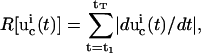 |
(6) |
where the first-order derivative of a control  with high-frequency features will have a large value and lead to an unfavorable cost
  . Here the time is sampled at T discrete points (t = t1, t2,…, tT). In this fashion, undesirable control forms and/or system responses can be automatically excluded from the GA evolutions.
The inversion module
The process of inversion seeks the model parameters (k in this illustration) that minimize ‖Xlab − Xcal‖ (i.e., the least squares norm of the difference between laboratory and calculated concentrations). The nonlinear nature of most bionetworks, the limited number of experiments, and the existence of laboratory data noise imply that large numbers of solutions are expected to exist for k that reproduce Xlab to within its error ranges. Most inversion methods indirectly deal with this issue by including additional restrictions or assumptions (e.g., locally linearizing the relationship between X and k), and only one or a few solutions are obtained. These methods can be unreliable because the extra conditions often do not truthfully represent the inherent nature of the biosystem, thereby possibly leading to false parameter values or a local sampling of the actual distribution of consistent parameters. When these parameters are utilized in further simulations under different conditions, quantitatively or even qualitatively incorrect predictions can result, and it is difficult to determine if the error arises from an incomplete model or from incorrect parameter values.
OI directly addresses the problem of multiple solutions with the inversion module aiming to identify the full family of solutions consistent with the laboratory data. The overall quality  of the extracted family of solutions is then returned to the control module for determining the control cost
  in Eq. 5, which then guides the selection of new controls aiming at finding one or a few experiments from which the narrowest possible parameter distributions can be obtained (see “The control module” section). Given a thorough GA search, the true value for each parameter should be included in the full solution family, and the resultant reliability of OI should be better than traditional methods. This work assumes that the true system is included in the proposed model (i.e., unmodeled dynamics are insignificant). However, the overall OI algorithm could seek out inconsistencies between the concentration data and calculations, which would indicate that the model is incomplete. Such a circumstance would call for a return to the analysis module for consideration of modifying the model.
The best means of characterizing the inversion quality depends on the level of detail in the extracted parameter distribution. In most biosystem model identifications, the extracted model parameters are not expected to form normal distributions due to nonlinear error propagation from the laboratory data to the parameters, hence many conventional treatments (e.g., those associated with assuming a Gaussian distribution) may not be appropriate in evaluating the inversion quality. When this is the case, the upper and lower limits identified for the solution family ki from the experiment with the ith control  can be used to conservatively represent the inversion quality. A convenient measure for the inversion quality
  corresponding to the ith control experiment is
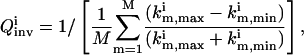 |
(7) |
where  and
and  are the upper and lower bounds of the consistent solutions for km, respectively. Another suitable function for evaluating
  is
is
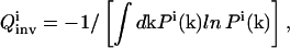 |
(8) |
which is an entropy-like measure, and Pi(k) is the probability distribution function of k determined from the inversion. In both Eqs. 7 and 8, a greater  value corresponds to a narrower parameter distribution, thus maximization of
  is sought by the control module over the evolving OI iterations.
Identifying the full solution family requires the inversion algorithm to have a global searching capability, thus another GA is used in the inversion module. Similar to the control GA, the evolution of the trial solutions for k is guided by an objective function, which compares the calculated system response to the experimental measurements. A suitable objective function is given by
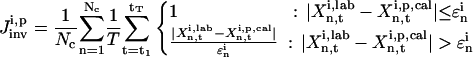 |
(9) |
where  represents the “fitness” of the pth trial set of parameters (p = 1, 2,…, P) for the ith control, Nc is the number of biomolecules selected for concentration measurements (i.e., the number of species in xc), and
  is the measured or estimated experimental error. When the difference between the laboratory concentrations
  and the concentrations
  calculated using the pth trial parameter set ki,p is smaller than
  for all the Nc species at all T time points, the trial set is considered as “good,” which gives
  The GA operation is iterated with the ith control
  until a sufficient number of solutions ki,p satisfying
  have been found out of the total set of P, so that a reasonable error distribution may be identified. If the laboratory data provided the distribution of errors for
  then Eq. 8 would be replaced by an inversion cost function comparing the calculated and the laboratory distribution.
In practice, the recovery of the full solution family can never be assured, but two approaches are used to practically address this difficulty. First, a large population size P (usually several hundred) and a high mutation rate (>30%) (Goldberg, 1989; Wall, 1995) are used in the inversion GA so that the searching avoids focusing on some local areas in the parameter space. Second, a simple convergence analysis algorithm is activated when the inversion quality  is good. In this analysis, the inversion is repeated with increasing GA population sizes. If
  remains constant, it is taken that the extracted solution family is a satisfactory discrete representation of the full solution distribution; if
  decreases, the inversion is carried out with larger populations until convergence of
  is achieved.
Another important issue in biosystem identification is the multiplicity of the candidate models. When this is the case, untailored experiments usually cannot provide enough information to distinguish among the multiple models. However, the learning algorithm in OI is specifically present to direct the controls to maximally assure that the correct model is found that produces dynamic behavior consistent with the laboratory data. This capability has been illustrated in related studies (B. Li et al., 2002; Geremia and Rabitz, 2001, 2002, 2003), and will be introduced for bionetwork model discrimination.
ILLUSTRATION
The operation of OI described this section is simulated in the identification of a tRNA proofreading mechanism (Okamoto and Savageau, 1984a). In this illustration, six reaction rate constants are extracted by OI, along with suboptimal and nonoptimal methods for comparison. The differential equations in the model (Okamoto and Savageau, 1984a) are numerically integrated (Hindmarsh, 1983; Petzold, 1983) to simulate the real experiments and the identification processes.
tRNA proofreading mechanism
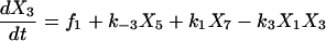
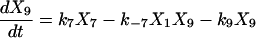
Proofreading mechanisms are widely utilized by organisms to maintain functional accuracy and integrity. They have been systematically studied, and the mechanism of isoleucyl–tRNAsynthetase proofreading valyl–tRNAIle in Escherichia coli is probably the best characterized (Okamoto and Savageau, 1984a,b). In this illustration, the mechanistic model proposed by Okamoto and Savageau (1984a) is used for the simulations (see this reference for further model details). The model contains 10 biochemical species, 10 kinetic equations, and 16 reaction rate constants. Table 1 lists the 10 species with their corresponding symbols and their steady-state concentrations. The 10 kinetic equations are shown below.
 |
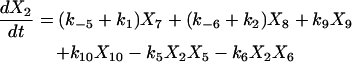 |
 |
 |
 |
 |
 |
 |
 |
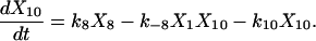 |
TABLE 1.
Chemical species in the tRNA proofreading model (Okamoto and Savageau, 1984a), their symbols, and steady-state concentrations
| Species | Symbol | Steady-state concentration (mol/l) |
|---|---|---|
| Ile-tRNA synthetase (IRS) | x1 | 2.81 × 10⁻⁸ |
| tRNAIle | x2 | 9.98 × 10⁻⁷ |
| Ile | x3 | 5.50 × 10⁻⁴ |
| Val | x4 | 3.10 × 10⁻³ |
| Ile-IRS | x5 | 1.56 × 10⁻⁶ |
| Val-IRS | x6 | 1.72 × 10⁻⁸ |
| Ile−IRS–tRNAIle | x7 | 3.39 × 10⁻⁶ |
| Val–IRS–tRNAIle | x8 | 9.71 × 10⁻⁹ |
| Ile–tRNAIle | x9 | 6.06 × 10⁻⁷ |
| Val–tRNAIle | x10 | 2.51 × 10⁻¹⁰ |
In the original paper, the kinetic rate constants were derived using a steady-state analysis (Okamoto and Savageau, 1984a), and the effect of data error was ignored. In this illustration, a measurement error taken as ±10% around the steady-state concentration is included in the simulated concentration measurements for all the species to evaluate the effect of data noise in extracting the rate constants. The available computing resources limited the inversion to extracting six rate constants (k1, k2, k5, k–5, k6, k−6), and the other 10 are set to the values from Okamoto's article (Okamoto and Savageau, 1984a). The search range for each of the six unknowns is arbitrarily chosen to be two orders of magnitude around the values estimated from the steady-state analysis in the original paper (Table 2). Larger ranges can be used if less is known about the approximate magnitudes of the unidentified rate constants, but the inversion procedure will be the same although the computational costs can increase.
TABLE 2.
Search ranges for the six rate constants to be identified
| Rate constant | Lower limit | Upper limit |
|---|---|---|
| k1(s−1) | −1.0 | 1.0 |
| k2(s−1) | 0.0 | 2.0 |
| k5(M−1s−1) | 6.0 | 8.0 |
| k−5(s−1) | 1.0 | 3.0 |
| k6(M−1s−1) | 9.0 | 11.0 |
| k−6(s−1) | 3.0 | 5.0 |
The numbers are over a logarithmic scale.
Sensitivity analysis
The sensitivities of the 10 species to variations in the six unknown rate constants are estimated in the analysis module using the RS-HDMR algorithm introduced in “The analysis module” section. First, S = 8,000 random samples of the six rate constants are generated from within their corresponding search ranges. The rate constants are transformed to a logarithmic scale to ensure an even distribution over the large search space. The concentrations of the 10 species are obtained at T = 10 time points (t = 30 s, 60 s,…, 300 s) by integrating the ODEs, using the laboratory-measured steady-state concentrations as initial values. The total sensitivities are first calculated and normalized by their corresponding steady-state concentrations (i.e., 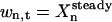 in Eq. 2). The first-order sensitivities of each species in x with respect to every rate constant in k are calculated at the 10 times. The sensitivities are time dependent, and no single time window is identified in which all six rate constants have favorable sensitivities; thus, the concentration measurements in the following (simulated) control experiments are carried out at all 10 times. The time-averaged first-order sensitivities are shown in Table 3. The percentage contributions of the first-order terms to the total sensitivities are also calculated for all the species (Table 4). The latter contributions are all >78%, suggesting that the second- and higher-order terms need not be used for estimating the species to use for concentration measurements. The species x4 is left out of the analysis in Table 4 because it is highly insensitive to variations in all six rate constants (see Table 3), which makes it difficult to obtain precise values for its sensitivities as well as its first-order percentage contribution. Quantitatively, x8 and x10 are the most sensitive species, with their sensitivities to k2, k6, and k−6 being considerably higher than all other species, and they are moderately sensitive to k5 and k−5. Based on this result, x8 and x10 are chosen for recording the dynamic concentration profiles of the system (i.e., xr = (x8, x10) and Nc = 2 in Eq. 9), although additional species can be considered for measurement. In general, including additional species will further refine the identified distribution of rate constants.
TABLE 3.
Time-averaged first-order sensitivities of the 10 species with respect to the six rate constants, normalized by their corresponding steady-state concentrations
| Species | k1 | k2 | k5 | k−5 | k6 | k−6 |
|---|---|---|---|---|---|---|
| x1 | 0.0046 | 0.0064 | 0.12 | 0.10 | 0.011 | 0.0083 |
| x2 | 0.0096 | 0.028 | 0.85 | 0.74 | 0.095 | 0.059 |
| x3 | 0.032 | 0.014 | 1.5 | 1.3 | 0.14 | 0.067 |
| x4 | 0.010 | 0.0045 | 0.0054 | 0.0021 | 0.024 | 0.014 |
| x5 | 0.012 | 0.021 | 0.46 | 0.40 | 0.069 | 0.034 |
| x6 | 0.0095 | 0.36 | 0.30 | 0.24 | 0.43 | 0.45 |
| x7 | 0.0098 | 0.0024 | 0.21 | 0.18 | 0.0038 | 0.0040 |
| x8 | 0.066 | 2.4 | 0.54 | 0.48 | 1.4 | 1.2 |
| x9 | 0.016 | 0.00080 | 0.23 | 0.19 | 0.0085 | 0.0049 |
| x10 | 0.040 | 3.7 | 0.29 | 0.20 | 2.1 | 1.8 |
TABLE 4.
Percentage of the first-order terms contributing to the total sensitivities
| Species | x1 | x2 | x3 | x5 | x6 | x7 | x8 | x9 | x10 |
|---|---|---|---|---|---|---|---|---|---|
| Percentage | 92 | 96 | 96 | 95 | 87 | 96 | 79 | 96 | 84 |
x4 is highly insensitive to all six rate constants, therefore its first-order contribution is not listed.
It can be seen from Table 3 that all 10 species are highly insensitive to k1. This property suggests that k1 may not be identified with high quality compared with the other rate constants, especially considering the presence of the laboratory data errors. For the same reason, it is expected that k2 may be identified with good quality owing to its high sensitivities upon x8 and x10.
The sensitivities of X8 and X10 with respect to constant influxes of x1, x3, and x4 are then calculated by the simple method introduced in the “Analysis module” section. x1, x3, and x4 are selected because they are relatively stable biomolecules, making them easier for manipulation in laboratory. G = 200 random samples of the six rate constants are generated, and the concentrations of the 10 species are obtained at the 10 time points for each sample. The sensitivities are calculated using Eq. 4 with normalization factor  . Among the three species, the flux of x4 causes variations of the highest magnitude in x8 and x10, thus it is selected as the single control for disturbing the system (i.e., xc = (x4)).
Identifying the rate constants
The identification is first carried out using the OI algorithm. Based upon the analysis results, I = 20 trial controls (see the “Control module” section) are first generated and applied to the system. Each control is a time-dependent flux of x4, expressed as a sum of four Gaussians
 |
(10) |
Because the lth Gaussian is encoded by three control parameters (am,l for m = 1, 2, and 3), a total of 12 control parameters are optimized by the control GA. In these simulations, the flux is maintained as positive by requiring that the GA confines its search to a1,l > 0, although negative fluxes can also be considered (e.g., by introducing inhibitors of the control species).
After applying the ith (i = 1, 2,…, I) chemical control flux, the concentrations of x8 and x10 are recorded at the 10 time points (t = 30 s, 60 s,…, 300 s) and the data is forwarded to the inversion module together with the information about the control fluxes. The inversion GA then randomly generates P = 500 trial solutions (see the “Inversion module” section) for each unidentified set of six rate constants for the ith control flux. Any “good” solution satisfying  (see Eq. 9) is saved, and the inversion GA evolves until in the last iteration, 500 good sets of rate constants are found, which forms a distribution corresponding to the ith control. The inversion quality
  is calculated from Eq. 7, and the cost
  is calculated from Eq. 5. In this illustration, no constraint term R is used, but the search ranges for the control parameters in Eq.10 are carefully set so that only relatively modest structure can arise in the controls.
  is used by the control GA to generate new controls aiming at higher
  values. The control GA is run for 25 generations, corresponding to a total of 25 × 20 = 500 experiments, but the best inversion quality is normally attained before the last control GA iteration.
A suboptimal inversion method is also applied to the system. In this method, the control GA evolution is replaced by 500 random chemical influxes of x4, and the full family of 500 good solutions is identified for each random control flux using the same inversion algorithm above. In fact, this method is not completely random because it still benefits from the information provided by the analysis module. To make another comparison, a nonoptimal inversion is carried out. In this inversion, 175 random influxes of x1, x3, and x4 (each flux is run separately for a total of 525 runs) are used as controls. Because the analysis module is not employed to provide the sensitivity information, the concentrations for all 10 species are used to extract 500 consistent solutions for each rate constant. Measuring all of the species will tend to give a generous advantage to performance of the nonoptimal inversion, as in reality, measuring every species simultaneously is usually not possible.
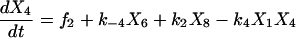
The upper (km,max/km) and lower limit (km,max/km) of the recovered rate constant distributions relative to the corresponding true values km are shown in Fig. 2 for all three approaches. All three methods reveal rate constant distributions that include the true values. Among the three temporal control influxes (x1, x3, and x4) used in the nonoptimal method, fluxes of x4 on the average lead to much better inversion quality, which is consistent with the sensitivity analysis results. The nonoptimal method recovers narrower distributions than the suboptimal method for all the rate constants. This enhanced performance arises because all 10 chemical species are measured in the nonoptimal approach whereas only two are measured in the suboptimal method. Integrating the learning algorithm into OI significantly enhances the inversion quality even with only two chemical species being measured. All of the rate constants extracted by OI are located within narrow ranges, and k6 and k−6 are improved significantly from the suboptimal and nonoptimal method. OI identifies k2 with the highest quality, and k1 with the largest uncertainty, also consistent with sensitivity analysis results. The two other approaches also extract k2 with the best inversion quality, although the inversion quality of k1 is not the worst among all six rate constants.
FIGURE 2.

Solution distributions for the six rate constants relative to their true values, revealed by OI, the suboptimal method, and the nonoptimal method. The true rate constants have relative value 1. The respective mean value of each distribution is also marked.
The mean values for each set of rate constants are also calculated (Table 5). Without including any additional constraints or assumptions, all of the mean values are identified to within 15% of the true values by using either OI or the suboptimal method. The nonoptimal method also identifies k2, k5, and k−5 with good quality, but the mean values of k1, k6, and k−6 deviate significantly from the true values. The mean values of the rate constant distribution revealed by the suboptimal method is more accurate than that recovered from the nonoptimal method, despite the fact that the breadth of the former distribution is larger than the latter.
TABLE 5.
The mean values of the rate constants and the relative deviations δ% of the mean from the true values
| Rate constant | True value | OI mean(δ%) | Suboptimal mean(δ%) | Nonoptimal mean(δ%) |
|---|---|---|---|---|
| k1(s−1) | 0.378 | 0.432(+14.3) | 0.375(−0.7) | 0.20(−47.1) |
| k2(s−1) | 60.3 | 60.3(0.0) | 60.3(0.0) | 60.3(0.0) |
| k5(M−1s−1) | 5.72 × 10⁷ | 5.76 × 10⁷(+0.7) | 5.75 × 10⁷(+0.5) | 6.37 × 10⁷(+11.4) |
| k−5(s−1) | 20.0 | 20.0(+0.0) | 19.9(−0.5) | 23.0(+15.0) |
| k6(M−1s−1) | 4.19 × 10⁹ | 3.80 × 10⁹(−9.3) | 3.99 × 10⁹(−4.7) | 5.67 × 10⁹(+35.3) |
| k−6(s−1) | 7.32 × 10³ | 6.61 × 10³(−9.7) | 6.94 × 10³(−5.2) | 9.85 × 10³(+34.6) |
The simulation results clearly indicate the advantage of employing the OI algorithm that extracts the full distribution for the model parameters. Traditional methods often only reveal a single value for each parameter and typically only linear estimates of the parameter error bars. If only a single value is obtained for a rate constant in this illustration, it can be located any place within the full distribution while still being consistent with the noisy laboratory data. Such a set of rate constants would likely fail to produce correct system performance under conditions beyond those used in the inversion. Note that extracting the full rate constant distribution does not necessarily require more experiments over that involved in obtaining a single inverted outcome by traditional methods. The optimally tuned multiple experiments serve to narrow down the breadth of the distribution. Using the same number of experiments, OI can locate the rate constants in much narrower ranges, thus their mean values have a higher possiblity of being near the true values. When the identified parameter distributions are employed in further simulations (e.g., for control purposes), the mean parameter values could be used if the distributions are sufficiently narrow. However, in general further simulations should use ensembles of parameters statistically sampled from their optimally identified distributions.
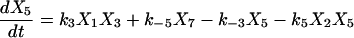
After 25 closed-loop iterations, many of the control fluxes that provide high inversion quality  become very similar. Fig. 3 shows the three controls found by OI that lead to the three best
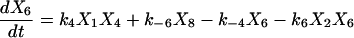
  values. The apparent similarity provides evidence that the control GA is converging to a single optimal control (experiment). In contrast, the best controls discovered in the suboptimal and nonoptimal approach differ considerably from each other and from those found by OI. This difference can also be seen from the X8 and X10 concentration profiles when these fluxes are applied in simulated experiments (see Figs. 4 and 5).
FIGURE 3.

The three control influxes that give the highest inversion quality  found by the OI operation, as well as the best controls found by the suboptimal and the nonoptimal methods.
FIGURE 4.

The concentration profiles of X8 when the optimal, the suboptimal, and the nonoptimal control fluxes are applied in simulated experiments.
FIGURE 5.

The concentration profiles of X10 when the optimal, the suboptimal, and the nonoptimal control fluxes are applied in simulated experiments.
Scalability issues
Extracting the full parameter distribution can be computationally intensive. In this illustration, parallel cluster computing techniques (Gropp et al., 1999) are used, in which the control GA runs on a “master” computer, while the inversion for each trial control is distributed to a different “slave” computer. In this way, the data obtained from all the controls can be processed simultaneously, which is especially advantageous when the control experiments can also be carried out in a parallel fashion. The OI simulations in this work were carried out on 21 1.0-GHz Linux workstations. Due to the stochastic nature of the algorithm, the simulations took one to four days. The computational cost may seem high for extracting six rate constants. However, it may be reduced significantly by using suitable mapping techniques, which helps to avoid integrating the model equations for each trial solution ki,p (G. Li et al., 2001; Geremia and Rabitz, 2001; Geremia et al., 2001).
In many real applications, the multiple runs of biological experiments can be expensive and time-consuming. An algorithm that virtually optimizes the control fluxes can be integrated into the analysis module to give an estimate of the time-dependent controls that may lead to the best inversion quality, thereby likely reducing both the number of wet experiments and the computational time for parameter identification from each set of experimental data. For example, maximizing the sensitivity of the system component concentrations with respect to variations in the rate constants can serve as the objective function for virtually optimizing the controls, due to the close relationship between the inversion quality and the sensitivity. Because the trial experiments begin with those virtually optimized controls, less experimental iterations may be needed to converge on a satisfactory inverse solution of high quality. In addition, optimizing the sensitivities requires much less computational time than extracting the rate constant distribution, thus the computational cost may also be reduced significantly. These topics will be addressed in future research.
Based on the results from quantum system identifications (G. Li et al., 2001; Geremia and Rabitz, 2001; Geremia et al., 2001), we believe that the OI algorithm (with the modifications described above) should be scalable and applicable to parameter identifications for increasingly large bionetwork models. Each inversion application will have its own particular features with regard to making the OI process as efficient as possible. The main point is to keep all of the closed-loop operations in Fig. 1 in sync with each other such that no component is idle waiting for another.
CONCLUSION
This paper introduces the concept of optimal identification of model parameters for complex biomolecular systems. The OI procedure consists of: a), system-tailored analysis tools, b), a learning algorithm for optimizing system controls, and c), a global inversion algorithm. All of these components work with the experimental capabilities for manipulating and monitoring biomolecular species. The optimal integration of these components is illustrated for extracting the rate constants of a tRNA proofreading model from simulated noisy experimental data, and the results are compared with suboptimal and nonoptimal methods.
The simulation results suggest that extracting the full family of rate constants consistent with the laboratory data provides higher reliability than extracting only one or a few values using traditional inversion approaches. By appropriately linking suitable computational algorithms with experimental capabilities, complex bionetwork models can be optimally identified using a minimal number of experiments.
Biology is going through a revolution driven by a series of technological breakthroughs in genomics (Lockhart and Winzeler, 2000), proteomics (Pandey and Mann, 2000), and metabolomics (Fiehn, 2002). These breakthroughs are providing increasingly powerful capabilities for quantitatively analyzing large numbers of biochemicals, as well as selectively manipulating their activities. The challenges ahead include: 1), introducing guidance to focus on developing the relevant data and 2), effectively utilizing the data to obtain a deeper understanding of complex biological systems. In this regard, OI not only provides a specific technique for efficiently identifying complex bionetwork models, but also illustrates the general concept of operating optimally, which we believe is the best way to perform expensive and time-consuming experiments and extract the most information from them.
Acknowledgments
We thank Tak-san Ho and Genyuan Li for helpful discussions.
The authors acknowledge support from the New Jersey Commission on Science and Technology and the National Science Foundation.
References
- Assion, A., T. Baumert, M. Bergt, T. Brixner, B. Kiefer, V. Seyfried, M. Strehle, and G. Gerber. 1998. Control of chemical reactions by feedback-optimized phase-shaped femtosecond laser pulses. Science. 282:919–922. [DOI] [PubMed] [Google Scholar]
- Bailey, J. E. 1998. Mathematical modeling and analysis in biochemical engineering: past accomplishments and future opportunities. Biotechnol. Prog. 14:8–20. [DOI] [PubMed] [Google Scholar]
- Bartels, R., S. Backus, E. Zeek, L. Misoguti, G. Vdovin, I. Christov, M. Murnane, and H. Kapteyn. 2000. Shaped-pulse optimization of coherent emission of high-harmonic soft x-rays. Nature. 406:164–166. [DOI] [PubMed] [Google Scholar]
- Bower, J. 2001. Computational Modeling of Genetic and Biochemical Networks. MIT Press, Cambridge, MA.
- Brogan, W. 1985. Modern Control Theory. Prentice Hall, Englewood Cliffs, NJ.
- Covert, M. W., C. Schilling, I. Famili, J. Edwards, I. I. Goryanin, E. Sekov, and B. O. Palsson. 2001. Metabolic modeling of microbial strains in silico. Trends Biochem. Sci. 26:179–186. [DOI] [PubMed] [Google Scholar]
- Csete, M., and J. Doyle. 2002. Reverse engineering of biological complexity. Science. 295:1664–1669. [DOI] [PubMed] [Google Scholar]
- Dayan, P., and L. F. Abbott. 2001. Theoretical neuroscience: computational and mathematical modeling of neural systems. The MIT Press, Cambridge, MA.
- Endy, D., and R. Brent. 2001. Modelling cellular behavior. Nature. 409:391–395. [DOI] [PubMed] [Google Scholar]
- Fiehn, O. 2002. Metabolomics—the link between genotypes and phenotypes. Plant Mol. Biol. 48:155–171. [PubMed] [Google Scholar]
- Geremia, J. M., and H. Rabitz. 2001. Global, nonlinear algorithm for inverting quantum-mechanical observations. Phys. Rev. A. 64:022710-1–13 [Google Scholar]
- Geremia, J. M., E. Weiss, and H. Rabitz. 2001. Achieving the laboratory control of quantum dynamics phenomena using nonlinear functional maps. Chem. Phys. 267:209–222. [Google Scholar]
- Geremia, J. M., and H. Rabitz. 2002. Optimal identification of Hamiltonian information by closed-loop laser control of quantum systems. Phys. Rev. Lett. 89:263902. [DOI] [PubMed] [Google Scholar]
- Geremia, J. M., and H. Rabitz. 2003. Optimal Hamiltonian identification: the synthesis of quantum optimal control and quantum inversion. J. Chem. Phys. 118:5369–5382. [Google Scholar]
- Giersch, C. 2000. Mathematical modelling of metabolism. Curr. Opin. Plant Biol. 3:249–253. [PubMed] [Google Scholar]
- Goldberg, D. 1989. Genetic Algorithms in Search, Optimization and Machine Learning. Addison-Wesley, Boston, MA.
- Gropp, W., E. Lusk, and A. Skjellum. 1999. Using MPI: portable parallel programming with the message-passing interface. The MIT Press, Cambridge, MA.
- Hasty, J., D. McMillen, F. Isaacs, and J. Collins. 2001. Computational studies of gene regulatory networks: in numero molecular biology. Nat. Rev. Genet. 2:268–279. [DOI] [PubMed] [Google Scholar]
- Hindmarsh, A. 1983. ODEPACK: A Systematized Collection of ODE Solvers. In Scientific Computing. North-Holland, Amsterdam, The Nethlerlands. 55–64.
- Hoffmann, A., A. Levchenko, M. L. Scott, and D. Baltimore. 2002. The IkB-NF-kB signaling module: temporal control and selective gene activation. Science. 298:1241–1245. [DOI] [PubMed] [Google Scholar]
- Jong, H. D. 2002. Modeling and simulation of genetic regulatory systems: a literature review. J. Comput. Biol. 9:67–103. [DOI] [PubMed] [Google Scholar]
- Judson, R., and H. Rabitz. 1992. Teaching lasers to control molecules. Phys. Rev. Lett. 68:1500–1503. [DOI] [PubMed] [Google Scholar]
- Ku, J., X. J. Feng, and H. Rabitz. 2004. Closed-loop learning control of bio-networks. J. Comput. Biol. In press. [DOI] [PubMed]
- Kunde, J., B. Baumann, S. Arlt, F. Morier-Genoud, U. Siegner, and U. Keller. 2000. Adaptive feedback control of ultrafast semiconductor nonlinearities. Appl. Phys. Lett. 77:924–926. [Google Scholar]
- Levis, R. J., G. Menkir, and H. Rabitz. 2001. Selective covalent bond dissociation and rearrangement by closed-loop, optimal control of tailored, strong field laser pulses. Science. 292:709–713. [DOI] [PubMed] [Google Scholar]
- Ljung, L. 1999. System Identification: Theory for the User. Prentice-Hall PTR, Upper Saddle River, NJ.
- Li, B., G. Turinici, V. Ramakrishna, and H. Rabitz. 2002. Optimal dynamical discrimination of similar molecules through quantum learning control. J. Phys. Chem. B. 106:8125–8131. [Google Scholar]
- Li, G., C. Rosenthal, and H. Rabitz. 2001. High dimensional model representations. J. Phys. Chem. A. 105:7765–7777. [Google Scholar]
- Li, G., S.-W. Wang, H. Rabitz, S. Wang, and P. Jaffe. 2002. Global uncertainty assessments by high dimensional model representations (HDMR). Chem. Eng. Sci. 57:4445–4460. [Google Scholar]
- Lockhart, D., and E. Winzeler. 2000. Genomics, gene expression and DNA arrays. Nature. 405:827–836. [DOI] [PubMed] [Google Scholar]
- Mayer, K. M., and F. H. Arnold. 2002. Directed protein evolution. In Encyclopedia of Evolution. Oxford University Press, UK. 268–271.
- McAdams, H. H., and A. Arkin. 1998. Simulation of prokaryotic genetic circuits. Annu. Rev. Biophys. Biomol. Struct. 27:199–224. [DOI] [PubMed] [Google Scholar]
- Mendes, P., and D. Kell. 1998. Non-linear optimization of biochemical pathways: applications to metabolic engineering and parameter estimation. Bioinformatics. 14:869–883. [DOI] [PubMed] [Google Scholar]
- Murray, J. 2002. Mathematical Biology. Springer-Verlag, New York, NY.
- Okamoto, M., and M. Savageau. 1984a. Integrated function of a kinetic proofreading mechanism: steady-state analysis testing internal consistency of data obtained in vivo and in vitro and predicting parameter values. Biochemistry. 23:1701–1709. [DOI] [PubMed] [Google Scholar]
- Okamoto, M., and M. Savageau. 1984b. Integrated function of a kinetic proofreading mechanism: dynamic analysis separating the effects of speed and substrate competition on accuracy. Biochemistry. 23:1710–1715. [DOI] [PubMed] [Google Scholar]
- Pandey, A., and M. Mann. 2000. Proteomics to study genes and genomics. Nature. 405:837–846. [DOI] [PubMed] [Google Scholar]
- Petzold, L. 1983. Automatic selection of methods for solving stiff and nonstiff systems of ordinary differential equations. SIAM J. Sci. Comput. 4:136–148. [Google Scholar]
- Rabitz, H., R. de Vivie-Riedle, M. Motzkus, and K. Kompa. 2000. Whither the future of controlling quantum phenomena. Science. 288:824–828. [DOI] [PubMed] [Google Scholar]
- Smolen, P., D. A. Baxter, and J. H. Byrne. 2000. Modeling transcriptional control in gene networks: methods, recent results, and future directions. Bull. Math. Biol. 62:247–292. [DOI] [PubMed] [Google Scholar]
- Wall, M. 1995. The GAlib Genetic Algorithm Package (copyright 1995–1996 Massachusetts Institute of Technology; copyright 1996–1999 Matthew Wall). Available at http://lancet.mit.edu/ga.
- Walter, E., L. Pronzato, and J. Norton. 1997. Identification of Parametric Models: From Experimental Data (Communications and Control Engineering). Springer Verlag, Heideberg, Germany.
- Weinacht, T., J. White, and P. Bucksbaum. 1999. Toward strong field mode-selective chemistry. J. Phys. Chem. A. 103:10166–10168. [Google Scholar]
- Yi, T.-M., Y. Huang, M. Simon, and J. Doyle. 2000. Robust perfect adaptation in bacterial chemotaxis through integral feedback control. Proc. Natl. Acad. Sci. USA. 97:4649–4653. [DOI] [PMC free article] [PubMed] [Google Scholar]
- Yokobayashi, Y., R. Weiss, and F. H. Arnold. 2002. Directed evolution of a genetic circiut. Proc. Natl. Acad. Sci. USA. 99:16587–16591. [DOI] [PMC free article] [PubMed] [Google Scholar]