Abstract
Self-assembly is beginning to be seen as a practical vehicle for computation. We investigate how basic ideas on tiling can be applied to the assembly and evaluation of circuits. We suggest that these procedures can be realized on the molecular scale through the medium of self-assembled DNA tiles. One layer of self-assembled DNA tiles will be used as the program or circuit that leads to the computation of a particular Boolean expression. This layer templates the assembly of tiles, and their associations then lead to the actual evaluation involving the input data. We describe DNA motifs that can be used for this purpose; we show how the template layer can be programmed, in much the way that a general-purpose computer can run programs for a variety of applications. The molecular system that we describe is fundamentally a pair of two-dimensional layers, but it seems possible to extend this system to multiple layers.
The notion of computation by interacting tiles dates from Wang (1) in the 1960s. The use of stable branched DNA molecules containing sticky ends to produce multidimensional constructs was proposed in the early 1980s (2). Winfree (3) suggested using Wang tiles based on branched DNA; Reif (4) and Lagoudakis and LaBean (5) have made suggestions on this approach. The assembly of DNA-based tiles into 2D periodic arrays has been reported several times with a variety of motifs (6–10). In addition, Rothemund has performed macroscopic-scale aperiodic self-assembly (11). Recently, a one-dimensional example of logical computation using DNA tiles has been realized (12, 19). Here, we point out that this cumulative XOR computation can also be viewed as a circuit that computes the parity of the input elements. We extend this concept to 2D and 3D circuit systems based on unusual DNA motifs. The unique approach we take to molecular computation is that we propose a self-assembled programmable molecular plane that can process a variety of different inputs in a second layer. We also note that 3D multilayered systems can be programmed similarly.
1. A Self-Assembling Template
A molecular circuit has been realized (12, 19) that, given an entry of n bits, outputs 1 if the number of 1s in the entry is odd and 0 otherwise; it computes the so-called parity function. The idea is simple: One produces a one-dimensional template (Fig. 1a) that represents the input sequence of values 0 and 1 for the circuit, together with an appropriate set of tiles (Fig. 1b). The tiles code the truth table of the XOR operation (Fig. 1c) denoted by the symbol ⊕. When the tiles are added to a solution containing the template, they self-assemble on it. One after the other, the tiles “glue” to the template as soon as a double site emerges. The assumption here is that a tile can attach to the template only if there is a double site to bind it. The first arrow in Fig. 1d illustrates the transition from the second to the third step of self-assembly. After five transition steps the complete structure is formed (Right); the value of the last added tile is the value of the parity function on the sequence 001101. The labeled corners used here are logically equivalent to the labeled edges of Wang tiles. The set of tiles is complete, i.e., for any possible output there is a tile with the same input. In Sections 3 and 4 we extend the idea of assembling tiles to a template, and we illustrate a way to compute Boolean expressions; in Section 5 we suggest how to construct more general programmable 3D devices. For the first application, we need to introduce some classical definitions and remarks on the theory of computation (see also refs. 13 and 14).
Figure 1.
Template (a) and set of tiles (b) that realize the truth table of the ⊕ operation (c). The pairs of values (x1,x2) on each row of the table correspond to the pair of values on the left-hand side of the tiles in b, and the value x1 ⊕ x2, associated with x1,x2 in the table, is recorded on the right-hand side of the corresponding tile. (d) Process of self-assembly of tiles on the template (a). The value 1 (circled) obtained at the end of the assembly, corresponds to the odd number of 1s in the input sequence 001101.
2. Boolean Functions and Boolean Expressions
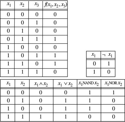
A Boolean function f(x1, … , xn) is a mapping from {0, 1}n to {0, 1}m, where n is the number of distinct Boolean variables, and we assume, for simplicity, m = 1. The behavior of f is described through a truth table that associates a value 0 or 1 with each combination of values 0,1 of x1, … , xn. For instance, the truth table in Fig. 2 Upper Left represents a function that answers 1 when exactly two of the three input variables take the value 1.
Figure 2.
Truth tables for some Boolean functions on the variables x1, x2, and x3.
A Boolean expression is either a Boolean variable or an expression of the form b(φ1, … , φn) where b is an elementary Boolean function and φ1, … , φn are Boolean expressions. Elementary Boolean functions, also called logical connectives, are, for example, ⊕ (XOR) mentioned above, ∧ (AND), ∨ (OR), ¬ (NOT), NAND, and NOR. The expressions φ1∧φ2 (conjunction of φ1 and φ2), φ1∨φ2 (disjunction), ¬φ1 (negation), φ1 NAND φ2, and φ1 NOR φ2 are Boolean expressions. The ⊕ connective can be defined out of ∧, ∨, ¬ as x ⊕ y ≡ (¬ x ∧ y) ∨ (x ∧ ¬ y); likewise, the NAND and NOR connectives are defined as x NAND y ≡ ¬ (x ∧ y) and x NOR y ≡ ¬ (x ∨ y), respectively. A logical connective has a fixed number of entries and a fixed number of exits. All the Boolean connectives above have two entries (x, y) and one exit, except for negation ¬, which has only one entry. The truth tables of ∧, ∨, ¬, NAND, and NOR are given in Fig. 2.
Any Boolean function can be defined as a Boolean expression by using the connectives ∧, ∨, ¬. For instance the Boolean expression representing f(x1, x2, x3) in Fig. 2 is (¬ x1 ∧ x2 ∧ x3) ∨ (x1 ∧ ¬ x2 ∧ x3) ∨ (x1 ∧ x2 ∧ ¬ x3). Given a truth table one can always write down the associated Boolean expression: One reads the rows of the truth table where the value of the function equals 1 and writes down a conjunction for each one of such rows. The conjunction describes whether the input variables are negated or not. For instance, in the first row of the truth table of f(x1, x2, x3) with value 1, we see that x1 takes value 0 and x2, x3 take value 1. The conjunction ¬ x1 ∧ x2 ∧ x3 describes this fact. The Boolean expression is then defined as the disjunction of all conjunctions representing values 1 in the truth table of the function.
For practical purposes, it can be useful to reduce the number of connectives used to define the set of Boolean functions. The pair of connectives ∧, ¬ is sufficient for this purpose since ∨ is definable from ∧, ¬ as follows x ∨ y ≡ ¬ (¬ x ∧ ¬ y). Similarly, the pair of connectives ∨, ¬ can do it. One single connective is also sufficient: By definition, the NAND operator is essentially a ∨, i.e., x NAND y ≡ ¬ x ∨ ¬ y, and in particular it allows one to define a negation as x NAND 1 ≡ ¬ (x ∧ 1) ≡ ¬ x. A similar argument shows that the connective NOR can be used to represent all Boolean functions.
2.1. Boolean Tree-Like Circuits (BTLCs).
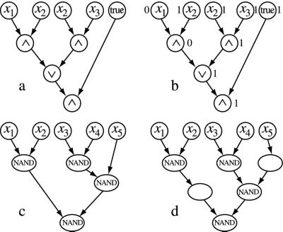
Another way to represent Boolean functions is through BTLCs. One starts with a tree-like-oriented graph. Each node in the graph is marked with a label that is either a Boolean variable xi, a designation of 1 (“true”) or 0 (“false”), or an elementary connective. Examples of a BTLC are illustrated in Fig. 3. If a node is marked with a Boolean variable or with true or false, then there are no incoming edges at that node. We call these nodes input nodes. If a node is labeled with a Boolean connective that has k inputs and 1 output, then the node should have exactly k edges going into it and n edges going out from it, where n ≥ 0 (to allow multiple uses of the output value). We call a node with no outgoing edges an output node.
Figure 3.
(a) A BTLC. (b) Evaluation of the circuit (a) on the entries 0,1,1; the input gate labeled “true” takes value 1. (c) The input x5 of the circuit is combined with an intermediate result, generated in the second row of the tree, through a NAND gate that lies in the third row. (d) Silent nodes are added to the circuit (c) to make it a BTLC with branches that pass through all rows.
A BTLC represents a Boolean function from {0, 1}n to {0, 1}m, where n is the number of Boolean variables labeling the input nodes, and m = 1 for simplicity. Assigning values to the input nodes leads to an assignment to all other nodes of the circuit, which is done by steps. Whenever all input nodes z1, z2, … , zk of a given gate are evaluated, then the gate itself is evaluated, and its output y is associated with the gate. This procedure is realized recursively on all gates from the inputs to the output of the circuit, and it is well founded because of the absence of oriented cycles in the underlying graph. Let's assign the values 0,1,1 to x1, x2, x3, in the circuit of Fig. 3a. The first step of the evaluation computes x1 ∧ x2 and x2 ∧ x3, and it associates values 0 and 1 with the outputs of the respective gates. The second step evaluates 0 ∨ 1 and fixes at 1 the gate in the third row. After the evaluation of the last conjunction (i.e., 1 ∧ 1, in the fourth row, where the gate true takes value 1), the circuit outputs 1 (Fig. 3b). For each Boolean expression there is an equivalent BTLC. The reader can easily verify that [(x∧ x2) ∨ (x2 ∧ x3)] ∧ true is the Boolean expression associated with the BTLC in Fig. 3a.
3. Self-Assembling Boolean Expressions: The Parts and the Whole
Based on the principle of self-assembly of tiles introduced in Section 1, we propose a general schema for the computation of Boolean expressions. The interest is twofold. We investigate on the one hand new self-assembling structures and on the other hand the possibility to compute arbitrary Boolean functions. We construct a structure that corresponds to a computation on a circuit by assembling two structures, one lying over the other: The lower layer is a template, and the upper one is formed by assembling a set of tiles on the template compatible with an array of “input” tiles. The template is a fixed support that codes a tree-like circuit. The array of input tiles provides the entries to the circuit. The assembly of the tiles depends on the information coded on both the tiles and the template. We first define the different parts playing a role in the construction (i.e., template, tiles, array) and then explain how they assemble (Section 3.3).
We need to impose a structural assumption on the representation of BTLC in the plane, owing to a technical point. We require that edges in the tree do not cross, and for the nodes, we ask that the top row of the tree contain input nodes only, that all input nodes lie in this row, and that a node x lying at row h is connected by edges to nodes occurring in row h − 1. The nodes of the circuit in Fig. 3c are not connected to nodes lying in adjacent rows. To overcome this problem, we allow an extra type of gate that simply passes on information (silently) without computing it (see Fig. 3d).
3.1. The Template.
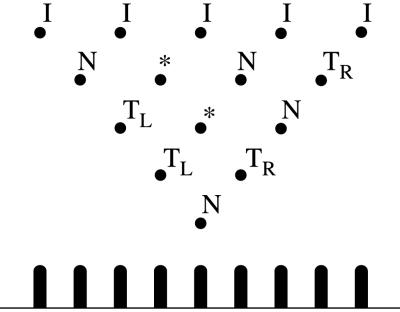
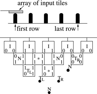
A template is a discrete triangle on a regular lattice. Fig. 4 (Upper) shows, the nodes of the triangle (black dots), called pawns, labeled in five different ways: I, N, TR, TL, and ∗. The labeled nodes correspond to gates in a tree-like circuit. Input gates are labeled I, and they lie on the first (Upper) row of the triangle. Computational gates are labeled N. They can be NAND gates, for instance. Any node in the discrete triangle, except those on the first row, can be labeled this way. The labels TR/TL refer to transmitter gates. They are silent gates that pass on information without altering the value. The information may be passed on from left to right (TL) or right to left (TR). The label ∗ corresponds to nodes that are not linked by edges in the tree-like circuit. A Boolean expression (or tree-like circuit) φ with n variable occurrences, can be represented by a template of n inputs and n rows of pawns. Each variable occurrence in φ corresponds to an input of the template. If the ith pawn (counting from the left) on the rth row of the template is identified by the pair (r, i), then the input pawns are called (0, i), with i = 1…n, and the pawn at the bottom of the template is (n, 1). The N gates in the template are located as follows: for each subexpression x1 NAND x2 in φ, we consider the pair of input pawns (0, i), (0, i + 1) associated to x1, x2 and label N the pawn (1, i); for each subexpression φL NAND φR of φ, there are two pawns (r, p), (s, q) corresponding to φL, φR (if φL, or φR, is a variable, we consider the input pawn associated to it); we label TR all the pawns along the diagonal of the template that begins at (s, q) and goes down from right to left, and we label TL all the pawns along the diagonal that begins at (r, p) and goes down from left to right, until the intersection node between the two diagonals is reached and we label it N. We repeat this process until the pawn (n, 1) of the template is labeled N. All pawns that have not been named will take the label ∗. Compare the circuit illustrated in Fig. 3d with the template of Fig. 4 (Upper). Physically, a template is realized as a 3D structure built on a surface with a triangle of pawns sticking out of it (see Fig. 4 and Section 3.4). Templates need not be triangular (see Sections 4 and 5).
Figure 4.
(Upper) A template of labeled pawns. (Lower) A vertical section of the template. The pawns are glued to a surface.
3.2. The Tiles and the Array of Entries.
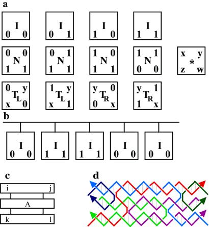
As in refs. 12 and 19, a tile is constructed in three parts where information is suitably coded (Fig. 5c). The labels i, j, k, l are values 0,1, and A codifies extra information that we call middle label. The pair of values i, j are called input values of the tile, and k, l are called output values of the tile. A molecular representation of the tile as a DNA triple crossover (TX) molecule (9) is shown in Fig. 5d. The values of i, j, k, and l are encrypted in the overhanging sticky ends shown at each of the corners of the tile. The coding of A is explained in Section 3.4; no coding is indicated in the molecular structure shown in Fig. 5d, where the middle helical domain terminates in hairpin loops.
Figure 5.
(a) Four types of basic tiles: input, I; computational, N; transmitter, TL/TR; and void, *. (b) An array of entries constituted by a bar to which a sequence of input tiles is attached. A tile (c) and its molecular representation as a TX molecule (d) are shown.
We define four types of tiles, each of them corresponding to a different labeling of the pawns of the template (see Fig. 5a). Input tiles, labeled I, represent the 0/1 values given as inputs to the circuit. (We could consider only the first and the fourth tile in the figure, but in principle, there is no reason for imposing this restriction.) Computational tiles, labeled N, represent the truth table for the NAND operator. The entries of the truth table are read on the upper side of the tile, and the output value is read on the bottom side. The output value appears both on the left and right of the tile, because it might be combined with some value arriving either from the left or the right of the circuit. Transmitter tiles, labeled TL/TR, pass the value 0 or 1 on the right (TR) or the left (TL). The letters x, y can take values in 0 or 1; therefore, there are 16 transmitter tiles. Void tiles, labeled ∗, do not pass on any information. The letters x, y, z, w take the values 0 or 1. There are 16 different types of void tiles. A template defines a Boolean expression that accepts n input values. In physical terms, to pass on the n values to the template, we need to create an array of entries made out of input tiles (Fig. 5b).
3.3. How the Construction Works.
Given a fixed template we superimpose on its first row of pawns an array of entries with the same length. Fig. 6 Upper shows a view from the side: The pawns of the first row of the template match the tiles of the array of entries. The template, array of entries, and computational, transmitter, and void tiles are added to the solution. The array of entries is considered to be preassembled on the template. The tiles glue to the template by self-assembly; they attach to adjacent tiles by matching both the input values (as described in Section 1) and the middle label of the adjacent pawns. This process repeats until the assembly is complete. An assembly process is illustrated in Fig. 6 Bottom.
Figure 6.
(Upper) A template and an array of entries viewed from the side. (Lower) The template of Fig. 4 is covered partly by a layer of tiles.
The output values of void tiles are not determined a priori by the structure. In fact, given two input values and a middle label ∗, we have tiles in solution with any pair of output values k, l. This freedom involves no complication because of the way that void tiles are combined with the rest of the tiles in the structure; void tiles never contribute input values to a computation. A similar consideration holds for transmitter tiles, where the values of an opposite pair of corners in the tile are free. Thus, if the void tile in the third row of Fig. 6 Lower had wound up in the position of the void tile in the second row, a TL tile with zeros on both its nontransmissive corners would have been available to fit on the left of the third row.
3.4. The Chemical Nature of Template and Pawns.
The system described in ref. 9 appears suitable for use as the pawn layer. This system consists of a 2D array containing helices that protrude from it. The AB array (Fig. 7) consists of TX tiles where the first domain of one tile connects to the third domain of the adjacent tile, leaving gaps large enough to insert a single DNA helix such as D. The C component is another TX tile, rotated (and renamed C′) by three nucleotide pairs ≈102°, to be nearly perpendicular to the array. Its central domain contains sticky ends to bind it to gaps in the array. Attachment of C′ leads to a helix protruding from the AB array in each direction. A specific set of helices that are the out-of-plane domains of C′-like tiles could function as a hard-wired bottom layer of pawns. The sticky ends on the protruding helices could be tuned to select for the proper types of TX tiles (N, TL, TR, ∗), which would be associated with the central helical domain of a TX tile that lies parallel to the AB array. The additional pawn sticky ends may entail an increase in stringency, which could be provided by having those sticky ends protected by imperfectly paired hairpin loops, only displaceable by the correct pairing partner. The outer domains would correspond to the Boolean input and output values of those tiles.
Figure 7.
A 2D array composed of two TX molecules, a rotated TX molecule, and a double-helical molecule. A schematic drawing shows the array components: A and B are TX molecules with geometrically represented sticky ends on all three domains. These tiles assemble to produce the AB array. C is a TX molecule with a single pair of sticky ends in its central domain; when they pair with A and B, C is rotated 102° relative to their plane (shown as C′). D is a double helix. The ABC′D array is shown below the AB array. The presence of the C′ units results in raised stripes, visible in an atomic force microscopy image (Right).
3.5. Error Detection.
A TX tile may fail to bind to a site in the array, leading to an error in the circuit. We envision the circuit to be evaluated many times by a large number of molecular arrays in solution. Those arrays containing gaps can be detected by adding a TX tile containing universal bases (e.g., 5-nitroindole) on their sticky ends. Such a tile could fill gaps but would not displace tiles already present. This TX would contain biotin groups, so that if it bound, the array could be removed by magnetic streptavidin bead treatment (e.g., ref. 15).
4. Programmable 2D DNA Devices
Consider a template of k pawns, and imagine each pawn to be equipped with a specific coding sequence Ai, for i = 1, … , k. A controlled assembly of the array allows knowing the position of each coding Ai in the template and opens the possibility to address the pawn i by means of its coding address Ai. Imagine also that each pawn can enter into a bi-stable state, and that this state could be controlled as well. Then, the template could be programmed and reused. It could be used to induce a controlled assembly of tiles, which can lead to the computation of an arbitrary Boolean function or the creation of 2D DNA layers satisfying specific properties. For instance, one can imagine large layers made of alternating strips of tiles of width k; fancier designs of 2D DNA layers and 3D arrays will be addressed in Section 5. In this section we analyze how to construct the units of a programmable 2D DNA device.
4.1. Programmable Pawns.
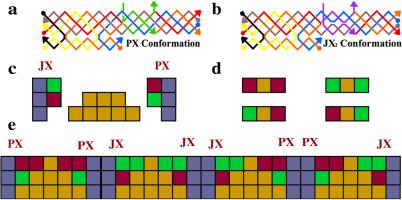
The pawns define the circuitry on which the tiles do the computation. We have shown above that it is possible to hard-wire a set of pawns by using TX molecules that are rotated out of the plane. However, flexibility would be maximized if the pawns themselves were programmable such that any circuit could be derived from a standard “pegboard” arrangement of pawns. The recent development of the PX-JX2 device (15) suggests a way to produce programmable pawns. The PX-JX2 device is programmed by the addition of strands to the solution. Fig. 8 shows the operation of the device: a illustrates the two different motifs, PX and JX2. The PX motif contains four strands, and it appears that two double helices are wrapped around each other. This arrangement of DNA contains two parallel double-helical domains where the strands cross-over between domains at every position. The JX2 structure is just like the PX structure except that two adjacent points of juxtaposition between the helical domains lack crossovers, leading to a global difference: JX2 is unwrapped by a half turn relative to PX. b shows a modified version of these structures that enables their interconversion. Two parallel strands near the middle of the PX molecule, one red and one blue, have been interrupted, and the missing DNA is replaced with two green “set” strands. The set strands contain single-stranded extensions (16); binding with the complete complements to the set strands leads to their removal (process I). Adding purple set strands (process II) produces the JX2 structure. Processes III and IV convert JX2 back to PX. It appears possible to embed the PX-JX2 device in a larger cassette (Fig. 9) that can be incorporated into a DNA lattice much like the C′ tiles above.
Figure 8.
Schematic drawings of the PX-JX2 device. (a) The PX and JX2 motifs. The PX motif consists of two helical domains formed by four strands that flank a central dyad axis. Two stands are drawn in red and two in blue. Watson–Crick base pairing is shown by thin horizontal lines. The same conventions apply to the JX2 motif. The letters A, B, C, and D and the color coding show that the bottom of the JX2 motif (C and D) is rotated 180° relative to the PX motif. (b) Principles of operation. On the left is a PX molecule. Its green set strands are removed by the addition of biotinylated green fuel strands (biotin is indicated by black circles) in process I. The intermediate is converted to the JX2 motif by the addition of purple set strands in process II. The JX2 molecule is converted to the PX molecule by processes III and IV.
Figure 9.
The PX-JX2 device is embedded into a five-helix motif. a and b show the two conformations. c schematizes the five helices as squares, including a green sticky end for JX and a purple one for PX, and also shows the protecting DX (yellow). d shows four possible TX middle domains, with sticky ends drawn colored. e shows four different middle domains paired to programmable pawns with the same coloration.
The cassette contains two parts, a motif on the left, and a PX-JX2 device on the right (Fig. 9 a and b). The bottom helical domain on the left is designed to insert into a 2D array containing gaps such as the AB array (Fig. 7). The left motif supports the PX-JX2 device on the right. The PX-JX2 device is switched from the PX state to the JX2 state by replacing the green strands with the purple strands. A DX protecting group is provided by the lattice (Fig. 9c). Only the helix that extends above it can interact with the tile-containing layer, and the other one is buried. PX-JX2 interconversion reverses the accessibility of the helices. A pair of devices could interact with the middle domain of a TX tile (Fig. 9d) to select whether it should be a tile associated with the N, TR, TL, or ∗ functions (Fig. 9e). To select for more than four functions, a tile more complex than TX would be needed. Recently, a six-helix bundle (6HB) tile has been devised (Fig. 10c) (F. Mathieu, C. Mao, and N.C.S., unpublished data). For a single-layer application, there are no obvious advantages to using such a tile over, say, a four-helix analog of the planar TX tile. However, 6HB may be more useful in 3D (see below).
Figure 10.
(a) Multiple-layer 3D assembly of tiles and pawns. (b) View from the top of a wall built out of tiles lying above “active” pawns. The white circles represent inactive pawns. (c) The 6HB. A view down the helix axes (Upper) and an oblique view (Lower) are shown. The helices are phased a half-turn apart as indicated by the alternating filled and unfilled circles in the drawings. (d) Three layers of 6HB tiles. The red circles are helices in 6HB tiles in a plane closer to the reader than the green circles; the green circles are 6HB tiles further from the reader. The features shown as three blue-filled circles in a row or three purple-filled blue circles are programmable TPJD motifs that interact with the red tiles and are closer yet to the reader. Two TPJD motifs abut each other to give a selectivity of eight possible tile types in any given layer. No TPJD motifs emanate up from the top layer or down from the bottom layer to give a sense of the intralayer arrangement.
5. Programmable 3D Arrays
Templates can be used to construct 3D objects: Consider a template with a shape that need not be a triangle, for instance let it be a “square,” and consider tiles equipped with a pawn. The first layer of assembled tiles (possibly guided by an array of entries) forms a second “template” of pawns that can be used for assembling a second layer of tiles, and so on (Fig. 10a). More sophisticated construction schemes can be devised. For instance, one might fill up the board only partially with tiles: By inserting appropriate coding in the pawns, one would be able to build “walls” with specified “heights” (Fig. 10b).
Fig. 10d illustrates the way that TPJD and 6HB motifs could be combined to produce a 3D arrangement. Illustrated are layers of 6HB tiles connected by pairs of adjacent TPJD programmable pawns. The bottom layer of 6HB motifs forms the basis for the attachment of the TPJD programmable pawns, which in turn template the assembly of the next layer. With this paired arrangement of pawns, eight different types of 6HB tiles could be used. Although there may ultimately be very difficult experimental problems with this type of 3D assembly, the components described above seem capable of serving to produce the 3D system described above. If the 6HB is used for the computational tiles and TPJD motifs are used for the pawns, one can build up a 3D structure by using the scheme illustrated in Fig. 10d.
Discussion and Comparison
We have outlined a system for computation on the molecular scale. We have described the arrangement of a programmable set of pawns that can produce a series of different logical operations in the level above them. Once assembled into a program, input data containing any values at all can be processed by this program. The pawns are based on sequence-dependent DNA devices that can be programmed individually. Each device pair can be responsible for generating four different specifications for the type of tile that is inserted in the computational array. The programs could be activated by the use of a device such as that described in ref. 17 to add specific strands on an electronic signal, thereby programming the pawns with a conventional computer. The key cost to operating the system will be generating the variety of strands necessary to label all the different pawns needed for the system. This cost could be decreased significantly by the use of mix-and-split syntheses (18) that encode sticky ends on the pawns to specify their location in the array as well as the sequence of the controlling strands. This approach will be described elsewhere.
In ref. 3, Winfree proposes (one- and two-dimensional) blocked cellular automata (BCA) as a Turing universal computing schema for molecular computation. Our architecture is also Turing-universal, since any circuit can be represented and computed within it. The basic difference with BCA is that here the program is “separated” from the data: The program is written on the pawns of the template, and the data (both input data and intermediate data obtained along the computation) are written on the second layer of the assembly. As a consequence, the template (already self-assembled) can be reprogrammed, while for BCA, new tiles must be redesigned for different programs. The simultaneous treatment of programs and data in BCA demands, in general, a larger number of tiles compared with the one required for our approach, although our motifs are more complex.
Acknowledgments
This work has been supported by National Institute of General Medical Sciences Grants GM-29554, Office of Naval Research Grant N00014-98-1-0093, National Science Foundation Grants CTS-9986512, EIA-0086015, DMR-01138790, and CTS-0103002, and Defense Advanced Research Planning Agency/Air Force Office of Scientific Research Grant F30602-01-2-0561.
Abbreviations
- BTLC
Boolean tree-like circuit
- TX
triple crossover
- 6HB
six-helix bundle
References
- 1.Wang H. Proceedings of the Symposium in the Mathematical Theory of Automata. Brooklyn, NY: Polytechnic Press; 1963. pp. 23–55. [Google Scholar]
- 2.Seeman N C. J Theor Biol. 1982;99:237–247. doi: 10.1016/0022-5193(82)90002-9. [DOI] [PubMed] [Google Scholar]
- 3.Winfree E. In: DNA Based Computing. Lipton E J, Baum E B, editors. Providence, RI: Am. Math. Soc.; 1996. pp. 199–219. [Google Scholar]
- 4.Reif J H. In: DNA Based Computers III. Rubin H, Wood D H, editors. Providence, RI: Am. Math. Soc.; 1999. pp. 217–254. [Google Scholar]
- 5.Lagoudakis M G, LaBean T H. In: DNA Computers V. Winfree E, Gifford D K, editors. Providence, RI: Am. Math. Soc.; 2000. pp. 141–154. [Google Scholar]
- 6.Winfree E, Liu F, Wenzler L A, Seeman N C. Nature (London) 1998;394:539–544. doi: 10.1038/28998. [DOI] [PubMed] [Google Scholar]
- 7.Liu F, Sha R, Seeman N C. J Am Chem Soc. 1999;121:917–922. [Google Scholar]
- 8.Mao C, Sun W, Seeman N C. J Am Chem Soc. 1999;121:5437–5443. [Google Scholar]
- 9.LaBean T, Yan H, Kopatsch J, Liu F, Winfree E, Reif J H, Seeman N C. J Am Chem Soc. 2000;122:1848–1860. [Google Scholar]
- 10.Sha R, Liu F, Millar D P, Seeman N C. Chem Biol. 2000;7:743–751. doi: 10.1016/s1074-5521(00)00024-7. [DOI] [PubMed] [Google Scholar]
- 11.Rothemund P W K. Proc Natl Acad Sci USA. 2000;97:984–989. doi: 10.1073/pnas.97.3.984. [DOI] [PMC free article] [PubMed] [Google Scholar]
- 12.Mao C, LaBean T, Reif J H, Seeman N C. Nature (London) 2000;407:493–496. doi: 10.1038/35035038. , and erratum (2000) 408, 750. [DOI] [PubMed] [Google Scholar]
- 13.Papadimitriou C. Computational Complexity. New York: Addison–Wesley; 1994. [Google Scholar]
- 14.Sipser M. Introduction to the Theory of Computation. Boston: PWS; 1996. [Google Scholar]
- 15.Yan H, Zhang X, Shen Z, Seeman N C. Nature (London) 2002;415:62–65. doi: 10.1038/415062a. [DOI] [PubMed] [Google Scholar]
- 16.Yurke B, Turberfield A J, Mills A P, Jr, Simmel F C, Neumann J L. Nature (London) 2000;406:605–608. doi: 10.1038/35020524. [DOI] [PubMed] [Google Scholar]
- 17.Gurtner C, Edman C F, Formosa R E, Heller M J. J Am Chem Soc. 2000;122:8589–8594. [Google Scholar]
- 18.Ohmeyer M H J, Swanson R N, Dillard L W, Reader J C, Asouline G, Kobayashi R, Wigler M, Still W C. Proc Natl Acad Sci USA. 1993;90:10922–10926. doi: 10.1073/pnas.90.23.10922. [DOI] [PMC free article] [PubMed] [Google Scholar]
- 19.Mao C, LaBean T, Reif J H, Seeman N C. Nature (London) 2000;408:750. doi: 10.1038/35035038. [DOI] [PubMed] [Google Scholar]


