Abstract
Auditory neurons preserve exquisite temporal information about sound features, but we do not know how the brain uses this information to process the rapidly changing sounds of the natural world. Simple arguments for effective use of temporal information led us to consider the reassignment class of time-frequency representations as a model of auditory processing. Reassigned time-frequency representations can track isolated simple signals with accuracy unlimited by the time-frequency uncertainty principle, but lack of a general theory has hampered their application to complex sounds. We describe the reassigned representations for white noise and show that even spectrally dense signals produce sparse reassignments: the representation collapses onto a thin set of lines arranged in a froth-like pattern. Preserving phase information allows reconstruction of the original signal. We define a notion of “consensus,” based on stability of reassignment to time-scale changes, which produces sharp spectral estimates for a wide class of complex mixed signals. As the only currently known class of time-frequency representations that is always “in focus” this methodology has general utility in signal analysis. It may also help explain the remarkable acuity of auditory perception. Many details of complex sounds that are virtually undetectable in standard sonograms are readily perceptible and visible in reassignment.
Keywords: auditory, reassignment, spectral, spectrograms, uncertainty
Time-frequency analysis seeks to decompose a one-dimensional signal along two dimensions, a time axis and a frequency axis; the best known time-frequency representation is the musical score, which notates frequency vertically and time horizontally. These methods are extremely important in fields ranging from quantum mechanics (1–5) to engineering (6, 7), animal vocalizations (8, 9), radar (10), sound analysis and speech recognition (11–13), geophysics (14, 15), shaped laser pulses (16–18), the physiology of hearing, and musicography.¶ A central question of auditory theory motivates our study: what algorithms do the brain use to parse the rapidly changing sounds of the natural world? Auditory neurons preserve detailed temporal information about sound features, but we do not know how the brain uses it to process sound. Although it is accepted that the auditory system must perform some type of time-frequency analysis, we do not know which type. The many inequivalent classes of time-frequency distributions (2, 3, 6) require very different kinds of computations: linear transforms include the Gabor transform (19), quadratic transforms [known as Cohen’s class (2, 6)] include the Wigner–Ville (1) and Choi–Williams (20) distributions, and higher-order in the signal, include multitapered spectral estimates (21–24), the Hilbert–Huang distribution (25, 26), and the reassigned spectrograms (27–32) whose properties are the subject of this article.
Results and Discussion
The auditory nerve preserves information about phases of oscillations much more accurately than information about amplitudes, a feature that inspired temporal theories of pitch perception (33–37). Let us consider what types of computation would be simple to perform given this information. We shall idealize the cochlea as splitting a sound signal χ(t) into many component signals χ(t,ω) indexed by frequency ω
 |
χ is the Gabor transform (19) or short-time Fourier transform (STFT) of the signal x(t). The parameter σ is the temporal resolution or time scale of the transform, and its inverse is the frequency resolution or bandwidth. The STFT χ is a smooth function of both t and ω and is strongly correlated for Δt < σ or Δω < 1/σ. In polar coordinates it decomposes into magnitude and phase, χ(t, ω) = |χ|(t, ω)eiφ(t,ω). A plot of |χ|2 as a function of (t, ω) is called the spectrogram (3, 38), sonogram (8), or Husimi distribution (2, 4) of the signal x(t). We call φ(t, ω) the phase of the STFT; it is well defined for all (t, ω) except where |χ| = 0. We shall base our representation on φ.
We can easily derive two quantities from φ: the time derivative of the phase, called the instantaneous frequency (31), and the current time minus the frequency derivative of the phase (the local group delay), the instantaneous time:
 |
Neural circuitry can compute or estimate these quantities from the information in the auditory nerve: the time derivative, as the time interval between action potentials in one given fiber of the auditory nerve, and the frequency derivative from a time interval between action potentials in nearby fibers, which are tonotopically organized (34).
Any neural representation that requires explicit use of ω or t is unnatural, because it entails “knowing” the numerical values of both the central frequencies of fibers and the current time. Eq. 2 affords a way out: given an estimate of a frequency and one of a time, one may plot the instantaneous estimates against each other, making only implicit use of (t, ω), namely, as the indices in an implicit plot. So for every pair (t, ω), the pair (tins, ωins) is computed from Eq. 2, and the two components are plotted against each other in a plane that we call (abusing notation) the (tins, ωins) plane. More abstractly, Eq. 2 defines a transformation T
The transformation is signal-dependent because φ has to be computed from Eq. 1, which depends on the signal x, hence the subscript {x} on T.
The transformation given by Eqs. 2 and 3 has optimum time-frequency localization properties for simple signals (27, 28). The values of the estimates for simple test signals are given in Table 1.
Table 1.
The values of the estimates for simple test signals
| Tones x=eiω0t | Clicks x = δ(t − t0) | Sweeps x=eiαt2/2 | |
|---|---|---|---|
| ωins(ω, t) = | ω0 | ω | αtins |
| tins(ω, t) = t − | t | t 0 | . . . |
So for a simple tone of frequency ω0, the whole (t, ω) plane is transformed into a single line, (t, ω0); similarly, for a “click,” Dirac delta function localized at time t0, the plane is transformed into the line (t0, ω); and for a frequency sweep where the frequency increases linearly with time as αt, the plane collapses onto the line αtins = ωins. (The full expression in the frequency sweep case is given in Appendix.) So for these simple signals the transformation (t, ω) → (tins, ωins) has a simple interpretation as a projection to a line that represents the signal. The transformation’s time-frequency localization properties are optimal, because these simple signals, independently of their slope, are represented by lines of zero thickness. Under the STFT the simple signals above transform into strokes with a Gaussian profile, with vertical thickness 1/σ (tones) and horizontal thickness σ (clicks).
These considerations lead to a careful restatement of the uncertainty principle. In optics it is well known that there is a difference between precision and resolution. Resolution refers to the ability to establish that there are two distinct objects at a certain distance, whereas precision refers to the accuracy with which a single object can be tracked. The wavelength of light limits resolution, but not precision. Similarly, the uncertainty principle limits the ability to separate a sum of signals as distinct objects, rather than the ability to track a single signal. The best-known distribution with optimal localization, the Wigner–Ville distribution (1), achieves optimal localization at the expense of infinitely long range in both frequency and time. Because it is bilinear, the Wigner transform of a sum of signals causes the signals to interfere or beat, no matter how far apart they are in frequency or time, seriously damaging the resolution of the transform. This nonlocality makes it unusable in practice and led to the development of Cohen’s class. In contrast, it is readily seen from Eq. 1 that the instantaneous time-frequency reassignment cannot cause a sum of signals to interfere when they are further apart than a Fourier uncertainty ellipsoid; therefore, it can resolve signals as long as they are further apart than the Fourier uncertainty ellipsoid, which is the optimal case. Thus, reassignment with instantaneous time-frequency estimates has optimal precision (unlimited) and optimal resolution (strict equality in the uncertainty relation).
We shall now derive the formula needed to implement numerically this method. First, the derivatives of the transformation defined by Eq. 2 should be carried out analytically. The Gaussian window in the STFT has a complex analytic structure; defining z = t/σ − iσω we can write the STFT as
 |
So up to the factor e(σω)2/2, the STFT is an analytic function of z (29). Defining
 |
we obtain in closed form
So the mapping is a quotient of convolutions:
where ∗ is the complex conjugate. Therefore, computing the instantaneous time-frequency transformation requires only twice the numerical effort of an STFT.
Any transformation F: (ω, t) → (ωins, tins) can be used to transform a distribution in the (ω, t) plane to its corresponding distribution in the (ωins, tins) plane. If the transformation is invertible and smooth, the usual case for a coordinate transformation, this change of coordinates is done by multiplying by the Jacobian of F the distribution evaluated at the “old coordinates” F−1(ωins, tins). Similarly, the transformation T given by Eqs. 2 and 3 transforms a distribution f in the (ω,t) plane to the (ωins, tins) plane, called a “reassigned f ” (28–30, 38)§. However, because T is neither invertible nor smooth, the reassignment requires an integral approach, best visualized as the numerical algorithm shown in Fig. 1: generate a fine grid in the (t, ω) plane, map every element of this grid to its estimate (tins, ωins), and then create a two-dimensional histogram of the latter. If we weight the histogrammed points by a positive-definite distribution f(t, ω), the histogram g(tins, ωins) is the reassigned or remapped f; if the points are unweighted (i.e., f = 1), we have reassigned the uniform (Lebesgue) measure. We call the class of distributions so generated the reassignment class. Reassignment has two essential ingredients: a signal-dependent transformation of the time-frequency plane, in our case the instantaneous time-frequency mapping defined by Eq. 2, and the distribution being reassigned. We shall for the moment consider two distributions: that obtained by reassigning the spectrogram |χ|2, and that obtained by reassigning 1, the Lebesgue measure. Later, we shall extend the notion of reassignment and reassign χ itself to obtain a complex reassigned transform rather than a distribution.
Fig. 1.
Reassignment. T{x} transforms a fine grid of points in (t, ω) space into a set of points in (tins, ωins) space; we histogram these points by counting how many fall within each element of a grid in (tins, ωins) space. The contribution of each point to the count in a bin may be unweighted, as shown above, or the counting may be weighted by a function g(t, ω), in which case we say we are computing the reassigned g. The weighting function is typically the sonogram from Eq. 1. An unweighted count can be viewed as reassigning 1, or more formally, as the reassigned Lebesgue measure. For a given grid size in (tins, ωins) space, as the grid of points in the original (t, ω) space becomes finer, the values in the histogram converge to limiting values.
Neurons could implement a calculation homologous to the method shown in Fig. 1, e.g., by using varying delays (39) and the “many-are-equal” logical primitive (40), which computes histograms.
Despite its highly desirable properties, the unwieldy analytical nature of the reassignment class has prevented its wide use. Useful signal estimation requires us to know what the transformation does to both signals and noise. We shall now demonstrate the usefulness of reassignment by proving some important results for white noise. Fig. 2shows the sonogram and reallocated sonogram of a discrete realization of white noise. In the discrete case, the signal is assumed to repeat periodically, and a sum replaces the integral in Eq. 1. If the signal has N discrete values we can compute N frequencies by Fourier transformation, so the time-frequency plane has N2 “pixels,” which, having been derived from only N numbers, are correlated (19). Given a discrete realization of white noise, i.e., a vector with N independent Gaussian random numbers, the STFT has exactly N zeros on the fundamental tile of the (t,ω) plane, so, on average, the area per zero is 1. These zeros are distributed with uniform density, although they are not independently distributed.
Fig. 2.
Analysis of a discrete white-noise signal, consisting of N independent identically distributed Gaussian random variables. (Left) |χ|, represented by false colors; red and yellow show high values, and black shows zero. The horizontal axis is time and the vertical axis is frequency, as in a musical score. Although the spectrogram of white noise has a constant expectation value, its value on a specific realization fluctuates as shown here. Note the black dots pockmarking the figure; the zeros of χ determine the local structure of the reassignment transformation. (Center) The reassigned spectrogram concentrates in a thin, froth-like structure and is zero (black) elsewhere. (Right) A composite picture showing reassigned distributions and their relationship to the zeros of the STFT; the green channel of the picture shows the reassigned Lebesgue measure, the red channel displays the reassigned sonogram, and the blue channel shows the zeros of the original STFT. Note that both distributions have similar footprints (resulting in yellow lines), with the reassigned histogram tracking the high-intensity regions of the sonogram and form a froth- or Voronoi-like pattern surrounding the zeros of the STFT.
Because the zeros of the STFT are discrete, the spectrogram is almost everywhere nonzero. In Fig. 2 the reassigned distributions are mostly zero or near zero: nonzero values concentrate in a froth-like pattern covering the ridges that separate neighboring zeros of the STFT. The Weierstrass representation theorem permits us to write the STFT of white noise as a product over the zeros × the exponential of an entire function of quadratic type:
where Q(z) is a quadratic polynomial and zi is the zeros of the STFT. The phase φ = Im ln G and hence the instantaneous estimates in Eq. 2 become sums of magnetic-like interactions
where
 |
and similarly for the instantaneous time; so the slow manifolds of the transformation T, where the reassigned representation has its support, are given by equations representing equilibria of magnetic-like terms.
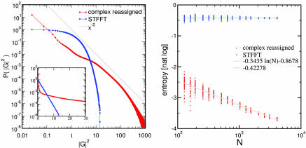
The reassigned distributions lie on thin strips between the zeros, which occupy only a small fraction of the time-frequency plane; see Appendix for an explicit calculation of the width of the stripes in a specific case. The fraction of the time-frequency plane occupied by the support of the distribution decreases as the sequence becomes longer, as in Fig. 3; therefore, reassigned distributions are sparse in the time-frequency plane. Sparse representations are of great interest in neuroscience (41–43), particularly in auditory areas, because most neurons in the primary auditory cortex A1 are silent most of the time (44–46).
Fig. 3.
The complex reassigned representation is sparse. We generated white-noise signals with N samples and computed both their STFFT and its complex reassigned transform on the N × N time-frequency square. The magnitude squared of either transform is its “energy distribution.” (Left) The probability distribution of the energy for both transforms computed from 1,000 realizations for N = 2,048. The energy distribution of the STFT (blue) agrees exactly with the expected e−x (see the log-linear plot inset). The energy distribution of the complex reassigned transform (red) is substantially broader, having many more events that are either very small or very large; we show in gray the power-law x−2 for comparison. For the complex reassigned transform most elements of the 2,048 × 2,048 time-frequency plane are close to zero, whereas a few elements have extremely large values. (Right) Entropy of the energy distribution of both transforms; this entropy may be interpreted as the natural logarithm of the fraction of the time-frequency plane that the footprint of the distribution covers. For each N, we analyzed 51 realizations of the signal and displayed them as dots on the graph. The entropy of the STFT remains constant, close to its theoretical value of 0.42278 as N increases, whereas the entropy of the complex reassigned transform decreases linearly with the logarithm of N. The representation covers a smaller and smaller fraction of the time-frequency plane as N increases.
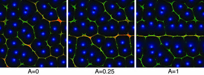
Signals superposed on noise move the zeros away from the representation of the pure signal, creating crevices. This process is shown in Fig. 4. When the signal is strong and readily detectable, its reassigned representation detaches from the underlying “froth” of noise; when the signal is weak, the reassigned representation merges into the froth, and if the signal is too weak its representation fragments into disconnected pieces.
Fig. 4.
Detection of a signal in a background of noise. Shown are the reassigned distributions and zeros of the Gabor transform as in Fig. 2 Right. The signal analyzed here is x = ζ(t) + Asinω0t, where ζ(t) is Gaussian white noise and has been kept the same across the panels. As the signal strength A is increased, a horizontal line appears at frequency ω0. We can readily observe that the zeros that are far from ω0 are unaffected; as A is increased, the zeros near ω0 are repelled and form a crevice whose width increases with A. For intermediate values of A a zigzagging curve appears in the vicinity of ω0. Note that because the instantaneous time-frequency reassignment is rotationally invariant in the time-frequency plane, detection of a click or a frequency sweep operates through the same principles, even though the energy of a frequency sweep is now spread over a large portion of the spectrum.
Distributions are not explicitly invertible; i.e., they retain information on features of the original signal, but lose some information (for instance about phases) irretrievably. It would be desirable to reassign the full STFT χ rather than just its spectrogram |χ|2. Also the auditory system preserves accurate timing information all of the way to primary auditory cortex (47). We shall now extend the reassignment class to complex-valued functions; to do this we need to reassign phase information, which requires more care than reassigning positive values, because complex values with rapidly rotating phases can cancel through destructive interference. We build a complex-valued histogram where each occurrence of (tins, ωins) is weighted by χ(t, ω). We must transform the phases so preimages of (tins, ωins) add coherently. The expected phase change from (t, ω) to (tins, ωins) is (ω + ωins)(tins − t)/2, i.e., the average frequency times the time difference. This correction is exact for linear frequency sweeps. Therefore, we reassign χ by histogramming (tins, ωins) weighted by χ(t, ω)ei(ω+ωins)(tins−t)/2. Unlike standard reassignment, the weight for complex reassignment depends on both the point of origin and the destination.
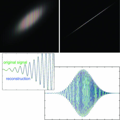
The complex reassigned STFT now shares an important attribute of χ that neither |χ|2 nor any other positive-definite distribution possesses: explicit invertibility. This inversion is not exact and may diverge significantly for spectrally dense signals. However, we can reconstruct simple signals directly by integrating on vertical slices, as in Fig. 5, which analyzes a chirp (a Gaussian-enveloped frequency sweep). Complex reassignment also allows us to define and compute synchrony between frequency bands: only by using the absolute phases can we check whether different components appearing to be harmonics of a single sound are actually synchronous.
Fig. 5.
Reconstruction of a chirp from the complex reassigned STFT. (Upper Left) STFT of a chirp; intensity represents magnitude, and hue represents complex phase. The spacing between lines of equal phase narrows toward the upper right, corresponding to the linearly increasing frequency. (Upper Right) Complex reassigned STFT of the same signal. The width of this representation is one pixel; the oscillation follows the same pattern. (Lower) A vertical integral of the STFT (blue) reconstructs the original signal exactly; the vertical integral of the complex reassigned transform (green) agrees with the original signal almost exactly. (Note the integral must include the mirror-symmetric, complex conjugate negative frequencies to reconstruct real signals.) (Lower Right) Full range of the chirp. (Lower Left) A detail of the rising edge of the waveform, showing the green and blue curves superposing point by point.
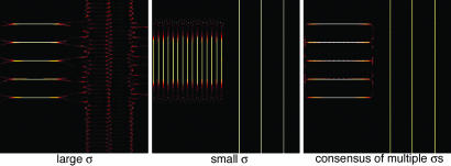
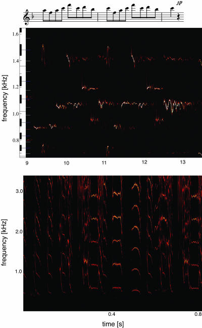
We defined the transformation for a single value of the bandwidth σ. Nothing prevents us from varying this bandwidth or using many bandwidths simultaneously, and indeed the auditory system appears to do so, because bandwidth varies across auditory nerve fibers and is furthermore volume-dependent. Performing reassignment as a function of time, frequency, and bandwidth we obtain a reassigned wavelet representation, which we shall not cover in this article. We shall describe a simpler method: using several bandwidths simultaneously and highlighting features that remain the same as the bandwidth is changed. When we intersect the footprints of representations for multiple bandwidths we obtain a consensus only for those features that are stable with respect to the analyzing bandwidth (31), as in Fig. 6. For spectrally more complex signals, distinct analyzing bandwidths resolve different portions of the signal. Yet the lack of predictability in the auditory stream precludes choosing the right bandwidths in advance. In Fig. 6, the analysis proceeds through many bandwidths, but only those bands that are locally optimal for the signal stand out as salient through consensus. Application of consensus to real sounds is illustrated in Fig. 7. This principle may also support robust pattern recognition in the presence of primary auditory sensors whose bandwidths depend on the intensity of the sound.
Fig. 6.
Consensus finds the best local bandwidth. Analysis of a signal x(t) composed of a series of harmonic stacks followed by a series of clicks; the separation between the stacks times the separation between the clicks is near the uncertainty limit 1/2, so no single σ can simultaneously analyze both. If the analyzing bandwidth is small (Center), the stacks are well resolved from one another, but the clicks are not. If the bandwidth is large (i.e., the temporal localization is high, Left), the clicks are resolved but the stacks merge. Using several bandwidths (Right) resolves both simultaneously.
Fig. 7.
Application of this method to real sounds. (Upper) A fragment of Mozart’s “Queen of the Night” aria (Der Hölle Rache) sung by Cheryl Studer. (Lower) A detail of zebra-finch song.
A final remark about the use of timing information in the auditory system is in order. Because G(z) (Eq. 4) is an analytic function of z, its logarithm is also analytic away from its zeros, and so
satisfies the Cauchy–Riemann relations, from where the derivatives of the spectrogram can be computed in terms of the derivatives of the phase and vice versa, as shown (29):
So, mathematically, time-frequency analysis can equivalently be done from phase or intensity information. In the auditory system, though, these two approaches are far from equivalent: estimates of |χ| and its derivatives must rely on estimating firing rates in the auditory nerve and require many cycles of the signal to have any accuracy. As argued before, estimating the derivatives of φ only requires computation of intervals between few spikes.
Our argument that time-frequency computations in hearing use reassignment or a homologous method depends on a few simple assumptions: (i) we must use simple operations from information readily available in the auditory nerve, mostly the phases of oscillations; (ii) we must make only implicit use of t and ω; (iii) phases themselves are reassigned; and (iv) perception uses a multiplicity of bandwidths. Assumptions i and ii led us to the definition of reassignment, iii led us to generalize reassignment by preserving phase information, and iv led us to define consensus. The result is interesting mathematically because reassignment has many desirable properties. Two features of the resulting representations are pertinent to auditory physiology. First, our representations make explicit information that is readily perceived yet is hidden in standard sonograms. We can perceive detail below the resolution limit imposed by the uncertainty principle that is stable across bandwidth changes, as in Fig. 5. Second, the resulting representations are sparse, which is a prominent feature of auditory responses in primary auditory cortex.
Appendix: Instantaneous Time Frequency for Some Specific Signals
Frequency Sweep.
x(t) + eiαt2/2:
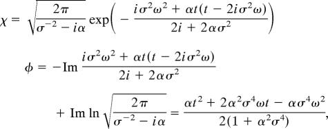 |
from where
Gaussian-Enveloped Tone.
x(t) = exp(−(t − t0)2/2λ2 + iω0(t − t0)), then the STFT has support on an ellipsoid centered at (t0, ω0) with temporal width and frequency width ; the total area of the support is (σ2 + λ2)/σλ, which is bounded by below by 2 and becomes infinite for either clicks or tones. The instantaneous estimates are
from where the two limits, λ → ∞ and λ → 0 give the first two columns of Table 1, respectively. The support of the reassigned sonogram has temporal width λ2/ and frequency width (σ/λ)/, so the reassigned representation is tone-like when λ > σ (i.e., the representation contracts the frequency axis more than the time axis) and click-like when λ > σ (the time direction is contracted more than the frequency). The area of the support has become the reciprocal of the STFT’s, σλ/(σ2 + λ2), whose maximum is 1/2 when σ = λ (i.e., when the signal matches the analyzing wavelet).
Acknowledgments
We thank Dan Margoliash, Sara Solla, David Gross, and William Bialek for discussions shaping these ideas; A. James Hudspeth, Carlos Brody, Tony Zador, Partha Mitra, and the members of our research group for spirited discussions and critical comments; and Fernando Nottebohm and Michale Fee for support of T.J.G. This work was supported in part by National Institutes of Health Grant R01-DC007294 (to M.O.M.) and a Career Award at the Scientific Interface from the Burroughs-Wellcome Fund (to T.J.G.).
Abbreviation
- STFT
short-time Fourier transform.
Footnotes
Conflict of interest statement: No conflicts declared.
Hainsworth, S. W., Macleod, M. D. & Wolfe, P. J., IEEE Workshop on Applications of Signal Processing to Audio and Acoustics, Oct. 21–24, 2001, Mohonk, NY, p. 26.
References
- 1.Wigner E. P. Phys. Rev. 1932;40:749–759. [Google Scholar]
- 2.Lee H. W. Phys. Rep. 1995;259:147–211. [Google Scholar]
- 3.Cohen L. Time-Frequency Analysis. Englewood Cliffs, NJ: Prentice–Hall; 1995. [Google Scholar]
- 4.Korsch H. J., Muller C., Wiescher H. J. Phys. A. 1997;30:L677–L684. [Google Scholar]
- 5.Wiescher H., Korsch H. J. J. Phys. A. 1997;30:1763–1773. [Google Scholar]
- 6.Cohen L. Proc. IEEE; 1989. pp. 941–981. [Google Scholar]
- 7.Hogan J. A., Lakey J. D. Time-Frequency and Time-Scale Methods: Adaptive Decompositions, Uncertainty Principles, and Sampling. Boston: Birkhauser; 2005. [Google Scholar]
- 8.Greenewalt C. H. Bird Song: Acoustics and Physiology. Washington, DC: Smithsonian Institution; 1968. [Google Scholar]
- 9.Margoliash D. J. Neurosci. 1983;3:1039–1057. doi: 10.1523/JNEUROSCI.03-05-01039.1983. [DOI] [PMC free article] [PubMed] [Google Scholar]
- 10.Chen V. C., Ling H. Time-Frequency Transforms for Radar Imaging and Signal Analysis. Boston, MA: Artech House; 2002. [Google Scholar]
- 11.Riley M. D. Speech Time-Frequency Representations. Boston: Kluwer; 1989. [Google Scholar]
- 12.Fulop S. A., Ladefoged P., Liu F., Vossen R. Phonetica. 2003;60:231–260. doi: 10.1159/000076375. [DOI] [PubMed] [Google Scholar]
- 13.Smutny J., Pazdera L. Insight. 2004;46:612–615. [Google Scholar]
- 14.Steeghs P., Baraniuk R., Odegard J. In: Applications in Time-Frequency Signal Processing. Papandreou-Suppappola A., editor. Boca Raton, FL: CRC; 2002. pp. 307–338. [Google Scholar]
- 15.Vasudevan K., Cook F. A. Can. J. Earth Sci. 2001;38:1027–1035. [Google Scholar]
- 16.Trebino R., DeLong K. W., Fittinghoff D. N., Sweetser J. N., Krumbugel M. A., Richman B. A., Kane D. J. Rev. Sci. Instrum. 1997;68:3277–3295. [Google Scholar]
- 17.Hase M., Kitajima M., Constantinescu A. M., Petek H. Nature. 2003;426:51–54. doi: 10.1038/nature02044. [DOI] [PubMed] [Google Scholar]
- 18.Marian A., Stowe M. C., Lawall J. R., Felinto D., Ye J. Science. 2004;306:2063–2068. doi: 10.1126/science.1105660. [DOI] [PubMed] [Google Scholar]
- 19.Gabor D. J. IEE (London) 1946;93:429–457. [Google Scholar]
- 20.Choi H. I., Williams W. J. IEEE Trans. Acoustics Speech Signal Processing. 1989;37:862–871. [Google Scholar]
- 21.Thomson D. J. Proc. IEEE; 1982. pp. 1055–1096. [Google Scholar]
- 22.Slepian D., Pollak H. O. Bell System Tech J. 1961;40:43–63. [Google Scholar]
- 23.Tchernichovski O., Nottebohm F., Ho C. E., Pesaran B., Mitra P. P. Anim. Behav. 2000;59:1167–1176. doi: 10.1006/anbe.1999.1416. [DOI] [PubMed] [Google Scholar]
- 24.Mitra P. P., Pesaran B. Biophys. J. 1999;76:691–708. doi: 10.1016/S0006-3495(99)77236-X. [DOI] [PMC free article] [PubMed] [Google Scholar]
- 25.Huang N. E., Shen Z., Long S. R., Wu M. L. C., Shih H. H., Zheng Q. N., Yen N. C., Tung C. C., Liu H. H. Proc. R. Soc. London Ser. A; 1998. pp. 903–995. [Google Scholar]
- 26.Yang Z. H., Huang D. R., Yang L. H. Adv. Biometric Person Authentication Proc. 2004;3338:586–593. [Google Scholar]
- 27.Kodera K., Gendrin R., Villedary C. D. IEEE Trans. Acoustics Speech Signal Processing. 1978;26:64–76. [Google Scholar]
- 28.Auger F., Flandrin P. IEEE Trans. Signal Processing. 1995;43:1068–1089. [Google Scholar]
- 29.ChassandeMottin E., Daubechies I., Auger F., Flandrin P. IEEE Signal Processing Lett. 1997;4:293–294. [Google Scholar]
- 30.Chassande-Mottin E., Flandrin P., Auger F. Multidimensional Systems Signal Processing. 1998;9:355–362. [Google Scholar]
- 31.Gardner T. J., Magnasco M. O. J. Acoust. Soc. Am. 2005;117:2896–2903. doi: 10.1121/1.1863072. [DOI] [PubMed] [Google Scholar]
- 32.Nelson D. J. J. Acoust. Soc. Am. 2001;110:2575–2592. doi: 10.1121/1.1402616. [DOI] [PubMed] [Google Scholar]
- 33.Licklider J. C. R. Experientia. 1951;7:128–134. doi: 10.1007/BF02156143. [DOI] [PubMed] [Google Scholar]
- 34.Patterson R. D. J. Acoust. Soc. Am. 1987;82:1560–1586. doi: 10.1121/1.395146. [DOI] [PubMed] [Google Scholar]
- 35.Cariani P. A., Delgutte B. J. Neurophysiol. 1996;76:1698–1716. doi: 10.1152/jn.1996.76.3.1698. [DOI] [PubMed] [Google Scholar]
- 36.Cariani P. A., Delgutte B. J. Neurophysiol. 1996;76:1717–1734. doi: 10.1152/jn.1996.76.3.1717. [DOI] [PubMed] [Google Scholar]
- 37.Julicher F., Andor D., Duke T. Proc. Natl. Acad. Sci. USA. 2001;98:9080–9085. doi: 10.1073/pnas.151257898. [DOI] [PMC free article] [PubMed] [Google Scholar]
- 38.Flandrin P. Time-Frequency/Time-Scale Analysis. San Diego: Academic; 1999. [Google Scholar]
- 39.Hopfield J. J. Nature. 1995;376:33–36. doi: 10.1038/376033a0. [DOI] [PubMed] [Google Scholar]
- 40.Hopfield J. J., Brody C. D. Proc. Natl. Acad. Sci. USA. 2001;98:1282–1287. doi: 10.1073/pnas.031567098. [DOI] [PMC free article] [PubMed] [Google Scholar]
- 41.Hahnloser R. H. R., Kozhevnikov A. A., Fee M. S. Nature. 2002;419:65–70. doi: 10.1038/nature00974. [DOI] [PubMed] [Google Scholar]
- 42.Olshausen B. A., Field D. J. Curr. Opin. Neurobiol. 2004;14:481–487. doi: 10.1016/j.conb.2004.07.007. [DOI] [PubMed] [Google Scholar]
- 43.Olshausen B. A., Field D. J. Nature. 1996;381:607–609. doi: 10.1038/381607a0. [DOI] [PubMed] [Google Scholar]
- 44.Coleman M. J., Mooney R. J. Neurosci. 2004;24:7251–7265. doi: 10.1523/JNEUROSCI.0947-04.2004. [DOI] [PMC free article] [PubMed] [Google Scholar]
- 45.DeWeese M. R., Wehr M., Zador A. M. J. Neurosci. 2003;23:7940–7949. doi: 10.1523/JNEUROSCI.23-21-07940.2003. [DOI] [PMC free article] [PubMed] [Google Scholar]
- 46.Zador A. Neuron. 1999;23:198–200. doi: 10.1016/s0896-6273(00)80770-9. [DOI] [PubMed] [Google Scholar]
- 47.Elhilali M., Fritz J. B., Klein D. J., Simon J. Z., Shamma S. A. J. Neurosci. 2004;24:1159–1172. doi: 10.1523/JNEUROSCI.3825-03.2004. [DOI] [PMC free article] [PubMed] [Google Scholar]


