Abstract
We propose what we believe is a new model to quantitatively describe the λ-phage SWITCH system. The model incorporates facilitated transfer mechanism of transcription factor, which can be simplified into a two-step reaction. We first sequentially obtain two indispensable parameters by fitting our model to experimental data of two simple systems, and then apply them to study the natural λ-SWITCH system. By incorporating the facilitated transfer mechanism, we find that in RecA− host Escherichia coli, the wild-type λ-lysogenic state is in a monostable regime rather than in a bistable regime. Furthermore, the model explains the weak role of Cro protein and probably sheds light on the evolution of λ-Cro protein, which is known to be structurally distinct from the other Cros in lambdoid family members.
INTRODUCTION
One of the paradigms for quantitative study of living organisms is λ-phage, which has two phenotypes: lysogeny and lysis. In the lysogenic state, its DNA is integrated into the genome of host cell; whereas in the lytic state it is duplicated inside the host until destroying the host and releasing its progeny (1). Upon ultraviolet induction, λ-phage will exit the lysogenic state and enter the lytic state (1). It is worthy to note that this transition is unidirectional, i.e., transition from lysis to lysogen does not exist. Thus lysogeny and lysis are not good indicators for the possible bistable system.
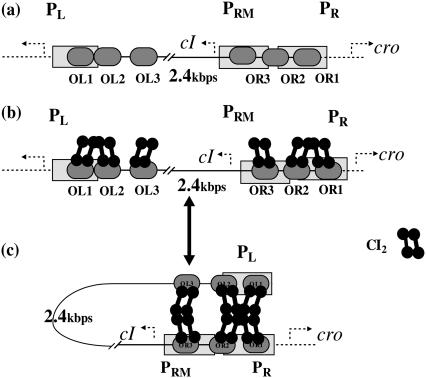
Among λ-phage genome, there is one element, called SWITCH, which is the most important regulation module for the life cycle of the infected Escherichia coli. As described in Fig. 1, the SWITCH consists of two genes (cI and cro), two promoters (PR and PRM), three operators (OR1, OR2, and OR3) in the OR region, and three other operators (OL1, OL2, and OL3) in the OL region. The molecular mechanism of the SWITCH has been elaborated for a long time, although the detail was modified recently (1). As shown in Fig. 1 a, when OR3 is free, gene cI can be transcribed by PRM promoter; its activity can increase 10-fold if OR2 is further occupied by CI2. When both OR1 and OR2 are free, gene cro can be transcribed from PR promoter by RNA polymerase. The OL region participates in the SWITCH's regulation via DNA looping as shown in Fig.1, b and c. The DNA loops between the OR and OL region is mediated by a CI octamer, which can repress the activity of the PR promoter. When an additional CI tetramer is presented beside the octamer, the activity of the PRM promoter will be repressed, too.
FIGURE 1.
λ-SWITCH system and the process of OL participation in the SWITCH. (a) SWITCH is composed of OR and OL promoter region and cI, cro genes. OR region consists of OR1, OR2, and OR3. PR completely overlaps OR1 and partially overlaps OR2, whereas PRM completely overlaps OR3 and partially overlaps OR2. (b and c) A schematic picture indicating the transition between unlooping configuration and looping configuration.
In the past 50 years, extensive experimental data have been accumulated on the behavior of the SWITCH and its components (1–7). Correspondingly, many mathematical models have formulated (4,7–15). These theoretical studies help us to understand the λ-SWITCH. Meanwhile, quantitative inconsistencies between numerical simulations and experimental measurements exist. For example, Bakk's model states that the concentration of free CI2 (effective part of CI protein) is <10 molecules per cell in the lysogenic condition. In other words, merely 10 dimers are available for controlling expressions of PR, PL, and PRM (12). Considering the fluctuation of protein number in cells (16), such a small number of the effective protein certainly leads to an unstable lysogenic state. In contract, it is observed that the lysogenic state of λ-prophage can sustain more than 5000 years (17). There must be other mechanisms that are responsible for the stable lysogenic state (12).
One of the possible revisions of the models is the distal regulation by DNA looping (18). Another mechanism of the stable lysogenic steady state should be facilitated transfer mechanism (FTM) of transcription factors (TFs) to their operators. FTM had been proved to exist extensively (19–25) and recently received increasing theoretical studies (26–31). It includes several microscopic processes: sliding along DNA contour, hopping along the DNA cylinder, and intersegment transfer between different segments (when the DNA exists crossover) within one DNA polymer (19,32). These three processes play important roles in the process of TFs searching for their binding sites. The mechanism has been raised in light of two experimental results. First, LacI repressor can bind to its specific site at a rate of 1010 M−1s−1, which is much larger than the calculated diffusion-controlled limiting rate for a one-step protein-DNA association in three-dimensional space, 107∼ 108 M−1s−1 (19). Second, there are experimental evidences that more than 90% of RNA polymerase attach on the nonspecific DNA site instead of existing freely in cytoplasm (33). These evidences imply that nonspecific binding may make a qualitative contribution to the process of TFs finding their target sites.
In general, FTM can be described by a sequential two-step reaction as Eq. 1. In contrast, the classical TF-operator interaction model uses two independent reactions as Eq. 2. In this article, we will adopt Eq. 1 instead of Eq. 2:
 |
(1) |
 |
(2) |
where [TF] is the concentration of free transcription factor, [D] is the concentration of nonspecific binding DNA site, [O] is the concentration operator of the transcription factor, and [TF − D] and [TF − O] represent, respectively, the concentrations of nonspecifically and specifically bound TFs. Under equilibrium condition,  is the equilibrium constant of TF binding to a nonspecific site on DNA,
  is the pseudoequilibrium constant for the second step reaction in Eq. 1, and
  is the equilibrium constant of free TF binding to its operator.
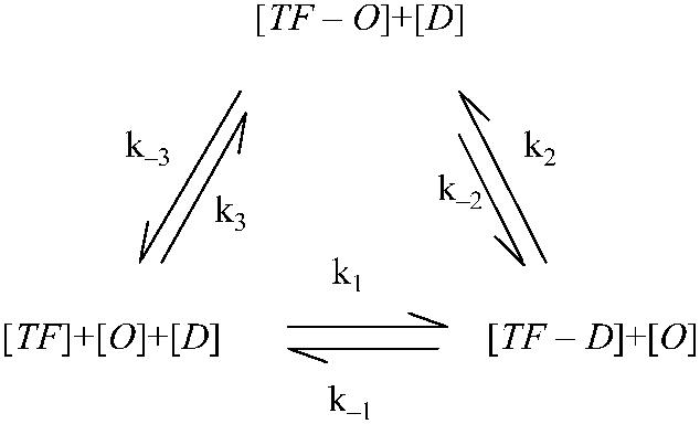
In fact, a complete reaction picture should integrate the two equations into a circular reaction loop (Eq. 3). The main difficulty of using the whole reaction loop is that more parameters are needed to fit from quantitative experimental data, which are rare. So we have to adopt a reduced one. Our model reduction (Eq. 1) is based on the following: on the energy profile of the reaction, for a TF the switching from the nonspecific to specific binding mode is quite smooth; no entropy costs at all (25), but the process of directly binding to the operator from the free mode needs much higher activation energy (34). As a consequence, in the reaction loop parameters k3(k−3) is much smaller than k2(k−2) and the reaction characterized by k3(k−3) can be neglected in the steady state. Difference of the parameters implies that even the equilibrium isn't held for the reaction of Eq. 2; the thermodynamic model still approximately works in the whole reaction:
 . .
|
(3) |
Our working outline in this article is the following: first, we use experimental data from a simple system (3) to determine an unknown parameter, then apply it in a more complicated system (4) that contains more unknown parameters. These parameters are induced by FTM or CI octamerization. Finally, we use these newly determined parameters in the model to study the λ-SWITCH system and to investigate its stability. We also discuss the role of Cro protein and raise a hypothesis about its evolution.
MODEL AND PARAMETER FITTING
Experimental systems
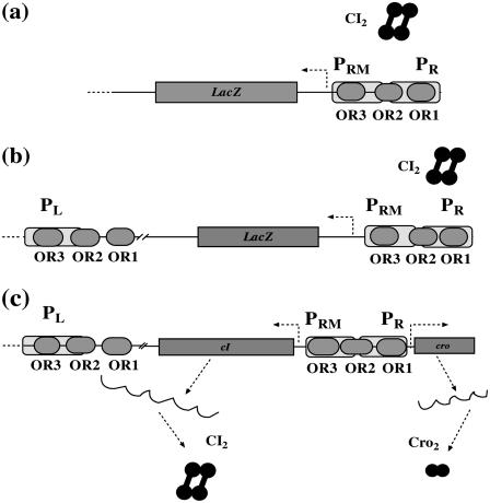
To obtain the essential parameters that are related to FTM and CI octamerization, we sequentially take account of three related experimental systems on λ-SWITCH (see Fig. 2):
A system only includes OR promoter regions and CI repressor (3) (see Fig. 2 a). In this system, LacZ reporter is under control of the PRM promoter, and the CI repressor is expressed from a plasmid. With the change of CI repressor concentration, the activity of PRM can be quantitatively determined by measuring the activity of the reporter gene LacZ.
The system is almost the same as the previous system, except that OL promoter regions are added (4) (see Fig. 2 b). Thus the octamer of CI possibly exists in this system.
The system is the wild-type λ-SWITCH system as described in Fig. 1 (Fig. 2 c).
FIGURE 2.
Three quantitative experimental systems. (a) The system involves OR promoter region, CI2 protein, and a reporter gene LacZ under PR promoter controlling. (b) The system adding an OL promoter region to the system (a) to incorporate the effect of CI octamerization. (c) The wild-type λ-SWITCH control element, in which CI2 and Cro2 was controlled, respectively, by PRM and PR promoters.
Using the model discussed below, we can fit the one free parameter  in system a. Then we use it in system b and fit the remaining free parameter
  . And last, we take the two fitted parameters into system c and investigate the steady state of lysogen of the λ-phage.
Definition of the parameter ΔGbasal_quasi 2dCI2
We take the FTM into account of our model. For two TFs (CI, Cro) bound to their operators in the λ-SWITCH system, a two-step reaction (Eqs. 4 a and 4 b) is formulated respectively instead of the two independent reactions (Eqs. 4 c and 4 d). The major difference between the two mechanisms lies in which part of CI2/Cro2 (called effective factor) directly responsible for the formation of [CI2 − O]/[Cro2 − O] complex. In the previous models, the effective factor is the free CI2 dimer; whereas in our model it is the CI2-DNA complex. For Eqs. 4 a and 4 b, the first step reaction takes place in cytoplasm, so that the equilibrium constants  are the same both in vitro and in vivo. But their second-step reactions are mediated by redundant DNA, and the quasi-equilibrium constant
  cannot be measured in vitro. In the following, we will make an effort to introduce an indispensable parameter to describe this quasi-equilibrium constant:
 |
(4 a) |
 |
(4 b) |
 |
(4 c) |
 |
(4 d) |
Because FTM exists in the process of TFs binding to their specific sites in vivo, i.e., in the second step of Eqs. 4 a and 4 b, the association rates that take the TFs to their operators are limited by diffusion, whereas the dissociation rates depend on the affinities between them (35,36). As a result, when a TF binds to two different operators in the same cell, the difference in their equilibrium constants, which equal the association rate divided by the dissociation rate, just depends on the difference in their dissociation rates, which are determined by their affinities (35). We assume that the difference in the affinities of a TF binding to two different operators is the same in vitro and in vivo, so that if we get the equilibrium constant of a TF to one of operators in vivo, we can deduce the equilibrium constants of the TF to other operators based on the existing affinities measured in vitro. Here we select, respectively, the constant of CI2 and Cro2 to OR1 as the unknown parameters  and
and  ; thus the equilibrium constants of CI2 binding to other operators can be calculated using
  , where
  represents
  . The same formula holds for Cro2. To be consistent with the measured data that are listed in Table 1, we translate the constants to free energy forms
  and
and  . For CI, the unknown parameter is fitted from to experimental data in Dodd et al. (3). Then using the measured data in Dodd et al. (4), we can deduct all the parameters
  (shown in Table 1). Unfortunately, there is no quantitative experimental data for Cro2. We have to use
  as a free parameter to discuss the behavior of the SWITCH system.
TABLE 1.
Parameter used in the model
| Parameter | Value (kcal/mol) | Parameter | Value (kcal/mol) | Parameter | Value (kcal/mol) | Activity of promoter | Value (LacZ units) |
|---|---|---|---|---|---|---|---|
 |
−10.4* |  |
−6.3† |  |
−0.6** |  |
1056* |
 |
−7.9* |  |
−5.1† |  |
−3* |  |
2* |
 |
−7.4* |  |
−7.7† |  |
−10.4** |  |
45* |
 |
−11* |  |
−6.3† |  |
−3 ∼ −8** |  |
406** |
 |
−9.3* |  |
−5.1† |  |
−11.1† |  |
265* |
 |
−9.6* |  |
−7.7† |  |
−8.7† |  |
0.5* |
 |
−3* |  |
−1† |  |
−3.6‡ | ||
 |
−3* |  |
−0.6† |  |
−6.5§ |  |
6.0 nM/min¶ |
 |
−3* |  |
−0.9† |  |
4.7n M/min¶ | ||
 |
−2.5* |  |
−1† |  |
0.01732/min¶ | ||
 |
−2.5* |  |
−0.6† | a |
 ** **
|
 |
0.15/min‖ |
 |
−2.5* |  |
−0.9† | [DNA] | 6.76 × 10⁻³(mol/L)§ |  |
0.0/min¶ |
Introduction of parameter ΔGoct
Parameter  represents the released energy when two CI tetramers form a CI octamer between OL and OR promoter regions by DNA looping. The parameter has not been measured yet. We will deduce it using another quantitative experiment of Dodd et al. (4). Furthermore, when two CI dimers exist beside the CI octamer, they can interact with each other, and another part of free energy,
  , will be released (4). However one single CI dimer binding at the OR region and another single CI dimer binding at the OL region cannot interact with each other or form the DNA looping (4).
The steady-state equation of λ-SWITCH phage
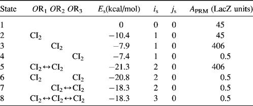
To formulate the thermodynamic model, we first analyze the possible microscopic configurations (also called states) for CI2/Cro2 binding to their operators in the three systems shown in Fig. 2. We calculate that system a has 8 states (see Table 2); system b has 73 = 64 + 9 states, including 9 looping states; and system c has 762 = 629 + 33 states, including 33 looping states. Note that the looping states represent the octamerized CI state existing between the OR and OL promoter regions; we do not exclude any possible looping state and corresponding unlooping state. For any sth state in anyone of the three systems, we employ Eq. 5 to represent its weight in the partition function:
 |
(5) |
where  is the total binding affinity of the sth state, which sum over all protein-operator, protein-protein binding affinities that exist in the sth state; R is the universal gas constant; and T is the absolute temperature. Typically,
  and
and  are the numbers of CI2 and Cro2 that bind to the regulation region in the sth state, respectively; [CI2 − D] and [Cro2 − D] are concentrations of the complex for CI2 and Cro2 binding to nonspecific DNA sites, respectively. These concentrations can be calculated using Eq. 6:
 |
(6) |
where [D] is the total E. coli chromosomal DNA concentration by basepair;  and
and  are the dimerizing affinities of Cro and CI, respectively; and
  and
and  represent the nonspecific binding affinities of CI2 and Cro2 to DNA, respectively. All of the parameters are listed in Table 1.
TABLE 2.
States of system a in Fig. 2 and the free energy for each state
The corresponding partition function can be written as below, in which summation is over all possible states in the system:
 |
(7) |
The probability of the sth state is
 |
(8) |
Meanwhile, following Dodd et al. (4), we set  and
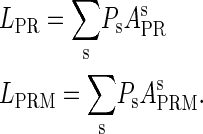
and  , respectively, to indicate the transcriptional activities of PR and PRM promoters in the sth state. There are four categories for PRM (basal, stimulated no looping, stimulated with looping, and repressed) and two categories for PR (basal and repressed) (Table 1). We adopt Dodd et al.'s empirical values, except that we reanalyze their data and properly change it in some cases. Thus we can obtain the activities (
 ,
, ) of PR and PRM promoters for a given system:
 |
(8a) |
In the previous models, the bistability of the λ-SWITCH (Fig. 2 c) is usually considered as equivalent to the coexisting λ-lysogenic and lytic states. In fact, the λ-SWITCH is just a part of the complex λ-regulation cascade, which is essentially responsible for the λ-lysogeny/lysis decision (17). We notice that when λ-phage exists in lysogeny, PRM promoter is the only high active promoter in the whole λ-genome. Correspondingly, CI protein is continually expressed (1). Under this situation, the λ-SWITCH can be decoupled from the whole λ-phage network and completely take charge of the λ-phenotype (lysogeny). Thus the stability of lysogeny of host E. coli is determined by the stability of λ-SWITCH. We can use a set of ordinary differential equations (see Eq. 9) to describe its dynamical property as previous models (11,37):
 |
(9) |
The stability property of lysogeny is decided by the steady state of Eq. 9, which gives Eq. 10. The function  and
and  is added and equaled to zero to study the steady-state's properties. Furthermore, the kinetic process of the system is investigated by a stochastic simulation using Gillespie's algorithm (38) (the detail of simulation is described in the Appendix):
 |
(10) |
where a is the constant, which relates the activities of PR and PRM in Dodd et al.'s experiments (4) to the transcription rate in the wild-type λ-SWITCH. Its value is determined by the fact that, in the physiological lysogenic state, the CI's total concentration is  and Cro's is close to zero.
  and
and  represent the synthesis rate of CI and Cro, respectively;
  and
and  represent the degraded rate of CI and Cro monomer, respectively. Here, we neglect the degradation of dimers because we take into account the effect of nonlinear degraded rate of proteins (39).
  is the dilution rate of
  and
and  due to growth of E. coli;
  and
and  represent, respectively, the total CI or Cro protein concentration; and
  and
and  represent, respectively, the concentration of free CI or Cro monomer. All the parameters are listed in Table 1.
RESULTS AND DISCUSSION
We first fit the two parameters  and
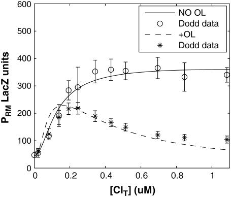
and  using the quantitative experimental data of systems a and b in Fig. 2; the results are presented in Fig. 3. Using the quantitative data in experimental system a, we fit the parameter for CI2 to be
  . Using this data, we obtain another parameter,
  , in experimental system b. The second parameter is slightly different with Dodd value −0.5k cal/mol (4). Note that in experimental system a, we adjust the empirical parameter
  of the PRM activity from 360 to 406 LacZ units. Because the states that characterize the PRM activity by
  never become absolutely dominant among all the possible states, the maximum value of their weight in the partition function is always <90%, thus we cannot directly take the highest experimental activity of PRM as
  . Besides reconciling with the experimental data, these results resolve the puzzle about the fluctuation of the available CI dimer: the available CI dimer's number increases around ninefold by incorporating FTM, so that the amplitude of internal fluctuation is reduced.
FIGURE 3.
PRM activity (LacZ units) versus the total CI concentration for system a (solid line) and system b (dashed line). The experimental data are kindly offered by Dodd et al. (3,4).
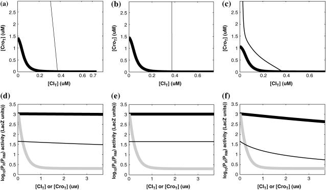
For the wild-type λ-phage, our model predicts that its lysogenic state is the only steady state when its host cell is RecA−. We adopt all the parameters determined in the two experimental systems (a, b) plus some new parameters (see Table 1). Since there are not quantitative data that can be used to fit the parameter , we vary it from −8 kcal/mol to −3 kcal/mol and investigate the steady state of the system using Eq. 10. The range is proper if we consider that its in vitro value should be −5.5 kcal/mol. The calculation results show that, no matter how we change the free parameter in this range, wild-type λ-SWITCH system only has a single stable steady state. The state is characterized by high CI concentration and very low Cro concentration see (Fig. 4, a–c). At the same time, because the SWITCH can be decoupled form the whole complex λ-regulation network and completely take charge of the physiological lysogenic phenotype of λ-phage, the single stable steady-state is lysogenic state of the prophage, i.e., the lysogenic phenotype should be absolutely monostable in RecA− condition. The similar result has been deduced by Santillan and Mackey (15), but their model does not consider the FTM or nonspecific binding protein. Notice that here we interpret the RecA− condition as
 in the model (see Table 1), because the degraded rate of CI can be neglected compared with its dilution rate in the RecA− lysogenic host E. coli (15).
FIGURE 4.
With the variation of parameter  , a–c, plot in the
  versus
  plane of
  curve (thick line) and
  curve (thin line), the cross point of the two curves gives the steady state of the system. (d–f) The activity of
  and
and  promoter change as a function of CI or Cro total concentration. The thick solid line represents
  , the thick shaded line represents
  , and the thin solid line represents
  . In these subfigures, the value of
 is −6.3 kcal/mol in a and d; −3 kcal/mol in b and e, and −8 kcal/mol in c and f.
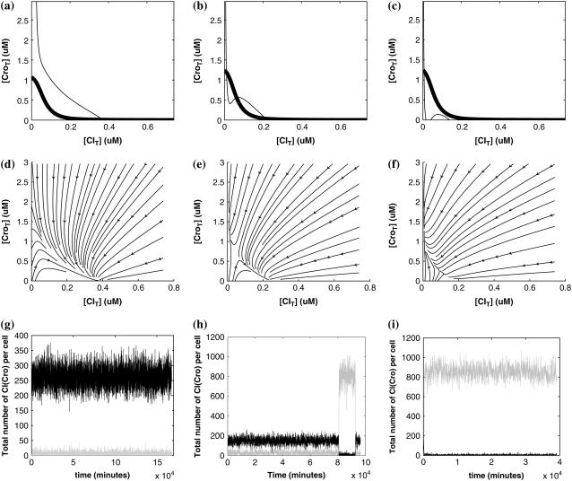
So far the experimental results about induction of lysogen are not contrary to the results. It is reported that the lysogen is extremely stable. The spontaneous induced rate from lysogen to lysis is even smaller than the mutation rate of λ-genome (5). Under this condition, it is believed that the majority of spontaneously induced lysogenic cells are not wild-type ones, but mutants that change in the cI gene or other regulating elements (6). Even without taking genetic mutations into account, such a tiny rate cannot be considered as a transition between two stable steady states of the λ-SWITCH element, since the kinetic fluctuations in λ-phage are enough to cause the lytic phenotype induction. Once the lytic phenotype is induced, the system cannot revert to its lysogenic phenotype any more, because the lysis of the E. coli cell will destroy the primary system (1). Furthermore, the mutant of  can simultaneously exist in immunity and anti-immunity states. Immunity state is characterized by high CI857 concentration and low Cro concentration; whereas anti-immunity state is characterized by low CI857 concentration and high Cro concentration (40). The reason for the bistability is the higher degraded rate of CI. In our model, the bistability will emerge with the increase of the degraded rate of CI (Fig. 5). To demonstrate the results, we first analyze the stability properties of the steady state and then implement the stochastic simulation. The results are compatible with each other (Fig. 5). With the change of control parameter,
  forms 0.0/min to 0.35/min, the SWITCH acquires and then loses the bistable property via twice saddle-node bifurcations. It is worth noting that the critical value of the control parameter in which the bistable state emerges or disappears cannot be used to give any prediction about the degradation rate of the CI monomer. As when the simulations are implemented, the free parameter
  is fixed to −7.5 kcal/mol.
FIGURE 5.
With the change of the control parameter  , the stability of λ-SWITCH is changed. In a, d, and g,
  ; in b, e, and h,
  ; and in c, f, and i,
  . Panels a–c represent the solution line of Eq. 10 in the [CIT] and [CroT] phase space. Panels d–f demonstrate the corresponding projections. Panels g–i indicate the corresponding stochastic simulations of the CI and Cro protein number per cell, in which the solid and shaded lines, respectively, represent the trajectories of CI and Cro protein numbers evolving. Each simulation implements 2 × 10⁶ steps.
The model also indicates that the Cro protein is a weak repressor in the λ-SWITCH compared to the CI repressor. To investigate the role of Cro protein, we use Eq. 8 to investigate the activity of the PR and PRM promoter as a function of Cro concentration, and the activity of the PR promoter as a function of CI concentration. From Fig. 4, d–f, it is obvious that the decrease of these promoters' activity by CI is much sharper than by Cro. In this study, the parameter  is changed from −8 kcal/mol to −3 kcal/mol and this variation doesn't qualitatively affect the difference (see Fig. 4, d–f).
This result is consistent with the experiments. Several experiments indicate that Cro2 is a weaker repressor for the PR, PL, and PRM promoters compared to CI2 (41,42). If we give up the two-step reaction constraint and just consider the binding energy of free CI2/Cro2 to their operators, we cannot obtain this result, because binding energy for CI2 to its best operator is 12.5 kcal/mol, whereas it is 13.4 kcal/mol for Cro2. As a consequence, Cro2 should be a more effective repressor than CI2 if the concentration of free Cro2 and CI2 is same. Even though two CI2 dimers show slightly stronger cooperation, according to the previous theories (10–15,43) the repression efficiency of Cro2 cannot be negligible compared to CI2. One may argue that the dimerization ability of Cro is weaker than CI, causing a weaker role of Cro2. But, in fact, λ-Cro is the only protein that has strong dimerization affinity in the Cro family of lambdoid phage. Its dimerizing affinity is 1000-fold of other Cros (44). So we cannot simply attribute the weak role of λ-Cro to the weaker dimerization.
In light of this model, we can raise a hypothesis about the physiological drive of the λ-Cro's secondary structure switching in the evolving process. Cordes et al. said that λ-Cro separated from other lambdoid CI/Cro protein family via an  - to
- to  -secondary structure switching event during evolution history and obtained a stronger dimerization ability (37). But one puzzle remains: if the role of Cro is just a weak repressor, and the weak dimerizing affinity is enough, why does λ-Cro evolve to obtain strong dimerization ability and high nonspecific binding affinity? The answer may be that it provides an additional level of gene regulation, which increases the λ-phage's adaptation (44). It is possible that such auxiliary regulation is achieved by FTM. According to Eqs. 5 and 6, the local concentration of DNA around the operators of Cro2 participate in the regulation, and are responsible for the repression ability of Cro2. A difference in the local DNA concentration will result in a difference in repression ability of Cro. In nature, at least two situations can make the difference in the local DNA concentration: when λ-DNA freshly injects into E. coli cell or when the λ-DNA has been integrated into E. coli chromosome. This difference causes Cro playing a different role in the infection process and in the induction process. If the local concentration of DNA is higher in the integrated condition, Cro will play a more important role in the induction process than in the infection process, and vice versa.
In summary, we have presented what we believe is a new quantitative model of the λ-SWITCH, which has incorporated the facilitated transfer mechanism via a two-step reaction. Besides reconciling with experimental data, it can easily explain the stability of lysogen and the weaker role of Cro. Nonetheless the model is a rough one, which uses some empirical results and some indispensable parameters. We believe it is helpful to understand the λ-SWITCH system and other regulation systems.
Acknowledgments
The authors thank Prof. C. Tang, H. Qian, and J. W. Little for their helpful discussions or communications, and I. B. Dodd for kindly offering his original experimental data and critically reading our manuscript. Special thanks to Prof. Terrence Hwa for his minicourse, which triggered the authors to conceive this research.
This work was partially supported by Chinese Natural Science Foundation and the Department of Science and Technology of China.
APPENDIX: STOCHASTIC SIMULATION OF λ-SWITCH
To incorporate transcription and translation noise, we separate Eq. 9 into transcription step and translation step. The corresponding reactions that happen in a cell are shown in Eqs. A1 and A2. The reactions in Eq. A1 account for, respectively, transcription of cI/cro mRNA, translation of CI/Cro protein, degradation of cI/cro mRNA, degradation of CI/Cro monomer, and dilution of total CI/Cro protein due to the host E. coli cell growth. Equation A2 is the same as Eq. 3 in the main text. They are considered as very fast compared with Eq. A1 and easily reach equilibrium. Our simulation is performed with these two sets of coupled stochastic reactions using the Monte Carlo algorithm described by Gillespie (38). In here, OPRM and OPR, respectively, represent the PRM and PR promoters. mRNAcI and mRNAcro, respectively, represent the mRNA transcript of cI and cro. The parentheses represent degradation. All the parameters are converted from Table 1 and shown in Table 3.
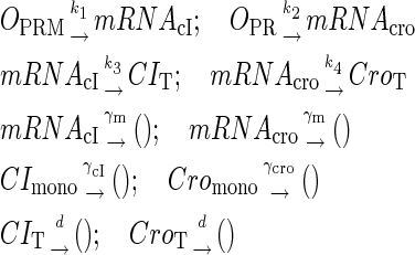 |
(A1) |
 |
(A2) |
TABLE 3.
Parameters for stochastic simulation
References
- 1.Ptashne, M. 2004. A Genetic Switch. 3rd. Cold Spring Harbor Laboratory Press, Cold Spring Harbor, New York.
- 2.Atsumi, S., and J. W. Little. 2004. Regulatory circuit design and evolution using phage lambda. Genes Dev. 18:2086–2094. [DOI] [PMC free article] [PubMed] [Google Scholar]
- 3.Dodd, I. B., A. J. Perkins, D. Tsemitsidis, and J. B. Egan. 2001. Octamerization of lambda CI repressor is needed for effective repression of P(RM) and efficient switching from lysogeny. Genes Dev. 15:3013–3022. [DOI] [PMC free article] [PubMed] [Google Scholar]
- 4.Dodd, I. B., K. E. Shearwin, A. J. Perkins, T. Burr, A. Hochschild, and J. B. Egan. 2004. Cooperativity in long-range gene regulation by the lambda CI repressor. Genes Dev. 18:344–354. [DOI] [PMC free article] [PubMed] [Google Scholar]
- 5.Little, J. W., D. P. Shepley, and D. W. Wert. 1999. Robustness of a gene regulatory circuit. EMBO J. 18:4299–4307. [DOI] [PMC free article] [PubMed] [Google Scholar]
- 6.Baek, K., S. Svenningsen, H. Eisen, K. Sneppen, and S. Brown. 2003. Single-cell analysis of lambda immunity regulation. J. Mol. Biol. 334:363–372. [DOI] [PubMed] [Google Scholar]
- 7.Darling, P. J., J. M. Holt, and G. K. Ackers. 2000. Coupled energetics of lambda cro repressor self-assembly and site-specific DNA operator binding II: cooperative interactions of cro dimers. J. Mol. Biol. 302:625–638. [DOI] [PubMed] [Google Scholar]
- 8.Ackers, G. K., A. D. Johnson, and M. A. Shea. 1982. Quantitative model for gene regulation by lambda phage repressor. Proc. Natl. Acad. Sci. USA. 79:1129–1133. [DOI] [PMC free article] [PubMed] [Google Scholar]
- 9.Reinitz, J., and J. R. Vaisnys. 1990. Theoretical and experimental analysis of the phage lambda genetic switch implies missing levels of co-operativity. J. Theor. Biol. 145:295–318. [DOI] [PubMed] [Google Scholar]
- 10.Aurell, E., and K. Sneppen. 2002. Epigenetics as a first exit problem. Phys. Rev. Lett. 88:048101. [DOI] [PubMed] [Google Scholar]
- 11.Zhu, X. M., L. Yin, L. Hood, and P. Ao. 2004. Calculating biological behaviors of epigenetic states in the phage lambda life cycle. Funct. Integr. Genomics. 4:188–195. [DOI] [PubMed] [Google Scholar]
- 12.Bakk, A., and R. Metzler. 2004. Nonspecific binding of the OR repressors CI and Cro of bacteriophage lambda. J. Theor. Biol. 231:525–533. [DOI] [PubMed] [Google Scholar]
- 13.Bakk, A., and R. Metzler. 2004. In vivo non-specific binding of lambda CI and Cro repressors is significant. FEBS Lett. 563:66–68. [DOI] [PubMed] [Google Scholar]
- 14.Bakk, A., R. Metzler, and K. Sneppen. 2004. Sensitivity of OR in phage lambda. Biophys. J. 86:58–66. [DOI] [PMC free article] [PubMed] [Google Scholar]
- 15.Santillan, M., and M. C. Mackey. 2004. Why the lysogenic state of phage lambda is so stable: a mathematical modeling approach. Biophys. J. 86:75–84. [DOI] [PMC free article] [PubMed] [Google Scholar]
- 16.Sato, K., Y. Ito, T. Yomo, and K. Kaneko. 2003. On the relation between fluctuation and response in biological systems. Proc. Natl. Acad. Sci. USA. 100:14086–14090. [DOI] [PMC free article] [PubMed] [Google Scholar]
- 17.Dodd, I. B., K. E. Shearwin, and J. B. Egan. 2005. Revisited gene regulation in bacteriophage lambda. Curr. Opin. Genet. Dev. 15:145–152. [DOI] [PubMed] [Google Scholar]
- 18.Vilar, J. M., and L. Saiz. 2005. DNA looping in gene regulation: from the assembly of macromolecular complexes to the control of transcriptional noise. Curr. Opin. Genet. Dev. 15:136–144. [DOI] [PubMed] [Google Scholar]
- 19.Berg, O. G., R. B. Winter, and P. H. von Hippel. 1981. Diffusion-driven mechanisms of protein translocation on nucleic acids. 1. Models and theory. Biochemistry. 20:6929–6948. [DOI] [PubMed] [Google Scholar]
- 20.Winter, R. B., O. G. Berg, and P. H. von Hippel. 1981. Diffusion-driven mechanisms of protein translocation on nucleic acids. 3. The Escherichia coli Lac repressor–operator interaction: kinetic measurements and conclusions. Biochemistry. 20:6961–6977. [DOI] [PubMed] [Google Scholar]
- 21.Shimamoto, N. 1999. One-dimensional diffusion of proteins along DNA. Its biological and chemical significance revealed by single-molecule measurements. J. Biol. Chem. 274:15293–15296. [DOI] [PubMed] [Google Scholar]
- 22.Dubertret, B., S. Liu, Q. Ouyang, and A. Libchaber. 2001. Dynamics of DNA-protein interaction deduced from in vitro DNA evolution. Phys. Rev. Lett. 86:6022–6025. [DOI] [PubMed] [Google Scholar]
- 23.Gowers, D. M., and S. E. Halford. 2003. Protein motion from non-specific to specific DNA by three-dimensional routes aided by supercoiling. EMBO J. 22:1410–1418. [DOI] [PMC free article] [PubMed] [Google Scholar]
- 24.Gowers, D. M., G. G. Wilson, and S. E. Halford. 2005. Measurement of the contributions of 1D and 3D pathways to the translocation of a protein along DNA. Proc. Natl. Acad. Sci. USA. 102:15883–15888. [DOI] [PMC free article] [PubMed] [Google Scholar]
- 25.Kalodimos, C. G., N. Biris, A. M. Bonvin, M. M. Levandoski, M. Guennuegues, R. Boelens, and R. Kaptein. 2004. Structure and flexibility adaptation in nonspecific and specific protein-DNA complexes. Science. 305:386–389. [DOI] [PubMed] [Google Scholar]
- 26.Sokolov, I. M., R. Metzler, K. Pant, and M. C. Williams. 2005. Target search of N sliding proteins on a DNA. Biophys. J. 89:895–902. [DOI] [PMC free article] [PubMed] [Google Scholar]
- 27.Lomholt, M. A., T. Ambjornsson, and R. Metzler. 2005. Optimal target search on a fast-folding polymer chain with volume exchange. Phys. Rev. Lett. 95:260603. [DOI] [PubMed] [Google Scholar]
- 28.Zhou, H. X. 2005. A model for the mediation of processivity of DNA-targeting proteins by nonspecific binding: dependence on DNA length and presence of obstacles. Biophys. J. 88:1608–1615. [DOI] [PMC free article] [PubMed] [Google Scholar]
- 29.Coppey, M., O. Benichou, R. Voituriez, and M. Moreau. 2004. Kinetics of target site localization of a protein on DNA: a stochastic approach. Biophys. J. 87:1640–1649. [DOI] [PMC free article] [PubMed] [Google Scholar]
- 30.Slutsky, M., and L. A. Mirny. 2004. Kinetics of protein-DNA interaction: facilitated target location in sequence-dependent potential. Biophys. J. 87:4021–4035. [DOI] [PMC free article] [PubMed] [Google Scholar]
- 31.Hu, T., A. Y. Grosberg, and B. I. Shklovskii. 2006. How proteins search for their specific sites on DNA: the role of DNA conformation. Biophys. J. 90:2731–2744. [DOI] [PMC free article] [PubMed] [Google Scholar]
- 32.von Hippel, P. H., and O. G. Berg. 1989. Facilitated target location in biological systems. J. Biol. Chem. 264:675–678. [PubMed] [Google Scholar]
- 33.Huang, Y. K., A. Revzin, A. P. Butler, P. O'Conner, D. W. Noble, and P. H. Von Hippel. 1977. Nonspecific DNA binding of genome regulating proteins as a biological control mechanism: Measurement of DNA-bound Escherichia coli Lac repressor in vivo. Proc. Natl. Acad. Sci. USA. 74:4228–4232. [DOI] [PMC free article] [PubMed] [Google Scholar]
- 34.Gromiha, M. M., M. G. Munteanu, I. Simon, and S. Pongor. 1997. The role of DNA bending in Cro protein-DNA interactions. Biophys. Chem. 69:153–160. [DOI] [PubMed] [Google Scholar]
- 35.Benos, P. V., A. S. Lapedes, and G. D. Stormo. 2002. Is there a code for protein-DNA recognition? Probab(ilistical)ly. Bioessays. 24:466–475. [DOI] [PubMed] [Google Scholar]
- 36.Saiz, L., and J. M. Vilar. 2006. Stochastic dynamics of macromolecular-assembly networks. Mol. Syst. Biol. 2:2006.0024 (Epub ahead of print). [DOI] [PMC free article] [PubMed]
- 37.Newlove, T., J. H. Konieczka, and M. H. Cordes. 2004. Secondary structure switching in Cro protein evolution. Structure. 12:569–581. [DOI] [PubMed] [Google Scholar]
- 38.Gillespie, D. T. 1977. Exact stochastic simulation of coupled chemical reactions. J. Phys. Chem. 81:2340–2361. [Google Scholar]
- 39.Buchler, N. E., U. Gerland, and T. Hwa. 2005. Nonlinear protein degradation and the function of genetic circuits. Proc. Natl. Acad. Sci. USA. 102:9559–9564. [DOI] [PMC free article] [PubMed] [Google Scholar]
- 40.Neubauer, Z., and E. Calef. 1970. Immunity phase-shift in defective lysogens: non-mutational hereditary change of early regulation of lambda prophage. J. Mol. Biol. 51:1–13. [DOI] [PubMed] [Google Scholar]
- 41.Folkmanis, A., W. Maltzman, P. Mellon, A. Skalka, and H. Echols. 1977. The essential role of the cro gene in lytic development by bacteriophage lambda. Virology. 81:352–362. [DOI] [PubMed] [Google Scholar]
- 42.Svenningsen, S. L., N. Costantino, D. L. Court, and S. Adhya. 2005. On the role of Cro in lambda prophage induction. Proc. Natl. Acad. Sci. USA. 102:4465–4469. [DOI] [PMC free article] [PubMed] [Google Scholar]
- 43.Aurell, E., S. Brown, J. Johanson, and K. Sneppen. 2002. Stability puzzles in phage lambda. Phys. Rev. E Stat. Nonlin. Soft Matter Phys. 65:051914. [DOI] [PubMed] [Google Scholar]
- 44.LeFevre, K. R., and M. H. Cordes. 2003. Retroevolution of lambda Cro toward a stable monomer. Proc. Natl. Acad. Sci. USA. 100:2345–2350. [DOI] [PMC free article] [PubMed] [Google Scholar]
- 45.Arkin, A., J. Ross, and H. H. McAdams. 1998. Stochastic kinetic analysis of developmental pathway bifurcation in phage lambda-infected Escherichia coli cells. Genetics. 149:1633–1648. [DOI] [PMC free article] [PubMed] [Google Scholar]


