Abstract
Molecular dynamics simulations of membrane proteins have provided deeper insights into their functions and interactions with surrounding environments at the atomic level. However, compared to solvation of globular proteins, building a realistic protein/membrane complex is still challenging and requires considerable experience with simulation software. Membrane Builder in the CHARMM-GUI website (http://www.charmm-gui.org) helps users to build such a complex system using a web browser with a graphical user interface. Through a generalized and automated building process including system size determination as well as generation of lipid bilayer, pore water, bulk water, and ions, a realistic membrane system with virtually any kinds and shapes of membrane proteins can be generated in 5 minutes to 2 hours depending on the system size. Default values that were elaborated and tested extensively are given in each step to provide reasonable options and starting points for both non-expert and expert users. The efficacy of Membrane Builder is illustrated by its applications to 12 transmembrane and 3 interfacial membrane proteins, whose fully equilibrated systems with three different types of lipid molecules (DMPC, DPPC, and POPC) and two types of system shapes (rectangular and hexagonal) are freely available on the CHARMM-GUI website. One of the most significant advantages of using the web environment is that, if a problem is found, users can go back and re-generate the whole system again before quitting the browser. Therefore, Membrane Builder provides the intuitive and easy way to build and simulate the biologically important membrane system.
Introduction
Membrane proteins play important roles in many cellular processes, such as cell signaling [1], [2], translocation of ions and small molecules [3]–[7], energy transduction process [8], [9], and cell-cell recognition [10]. They are quantitatively significant as well. For example, 20–30% of the protein-encoding regions of known genomes encode membrane proteins [11], suggesting that the human genome encodes about 8,000 membrane proteins. Furthermore, about 50% of these membrane proteins are considered putative drug targets [12]. Due to the biological and pharmaceutical importance of membrane proteins, considerable experimental efforts have been made to better understand their structure and function in membrane environments. As a result of technological advances in various fields, more and more membrane protein structures have become available [13], although their numbers are still much smaller than those of globular proteins [14].
Molecular dynamics (MD) simulations of membrane proteins have provided deeper insights into their functions and interactions with surrounding environments at the atomic level [15]–[18]. In particular, when combined with computationally sophisticated and intensive free energy techniques, MD simulations can elucidate the microscopic origins or driving forces of biological functions. Compared to solvation of globular proteins, however, building a realistic protein/membrane complex is still challenging and requires considerable experience with simulation software. The main difficulty in building such a complex system arises from how to insert a protein into a lipid bilayer.
There are two popular methods commonly used to build a realistic protein/membrane complex. In the first method, lipid-like pseudo atoms are first distributed around a protein and then replaced by lipid molecules one at a time [19]–[21]. Individual lipid molecules are randomly selected from a lipid library that contains various conformations of lipid molecules. This method allows one to easily control the system size and the number of lipid molecules while it generates a lipid bilayer nicely packed around the protein. In the second method, a hole is first created in a pre-equilibrated lipid bilayer and then the membrane protein is inserted into the hole [22]–[24]. In general, weak repulsive radial forces perpendicular to the membrane normal are applied to a lipid bilayer until the hole is large enough to accommodate the protein. This method provides a well-equilibrated lipid bilayer, and one might expect less equilibration time than in the first method. For the sake of convenience, the first method is called the “replacement method” and the second method is called the “insertion method” hereinafter. Although both methods are well explained in the literature [19]–[24], considerable efforts and experiences with MD simulation software are required to build a realistic protein/membrane system.
The CHARMM-GUI website (http://www.charmm-gui.org) provides a graphical user interface (GUI) of a collection of modules that helps users to setup their MD simulations in a web browser. Membrane Builder, one of the modules in CHARMM-GUI, aims to help users to build a sophisticated protein/membrane system easily and interactively in a web browser through a generalized and automated building process including system size determination as well as generation of lipid bilayer, pore water, bulk water, and ions. The main idea is to let users define various parameters, such as the system size and shape, ion concentration, lipid type, and bilayer generation method in a full GUI fashion, and to provide the generated complex structure and input files. However, default values that were elaborated and tested extensively are given in each step to provide reasonable options and starting points for both non-expert and expert users. We have further developed and generalized both replacement and insertion methods to adopt them in Membrane Builder to build a membrane bilayer efficiently.
In this paper, we describe and illustrate the generalized protein/membrane complex building process. Its efficiency has been examined by building a total of 90 protein/membrane complexes of 12 transmembrane and 3 interfacial membrane proteins, that have considerably different shapes and sizes, with three types of lipid bilayers (dimyristoylphosphatidylcholine (DMPC), dipalmitoylphosphatidylcholine (DPPC), and palmitoyloleoylphosphatidylcholine (POPC)) and two different system shapes (rectangular and hexagonal). Each equilibrated system is available at the archive on the CHARMM-GUI website.
Results
Generalized Protein/membrane Complex Building Process
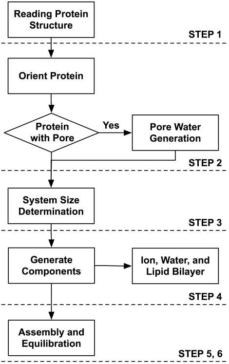
As shown in Fig. 1, the overall process to build a protein/membrane complex has been generalized and automated in six subsequent steps. Each step was designed to incorporate users' specific options through a web browser, and generate and run CHARMM input files. Individual input and output files including generated structures as well as an archive of all the created files are available in each step. One can visualize the generated system in each step so that, if necessary, one can go back to the previous step and modify the options interactively. Video demonstrations on how to use Membrane Builder (“Membrane Builder Lecture” and “Membrane Builder Demo”) are available on the CHARMM-GUI website.
Figure 1. Overview of generalized process of building protein/membrane complex system.
Step 1–PDB Reading
The objective of this step is to read a protein structure, manipulate it if necessary, and generate a structure topology file. Users can upload their own pre-oriented protein structure, or specify PDB entry ID and a database, either of PDB database [14] or OPM database [25]. Protein structures from OPM database are pre-oriented with respect to the membrane normal (the Z-axis by definition), so that one may use them without any modification of the protein orientation (see Step 2 below). In this step, users can select a model structure (in the case of NMR ensemble structures) or a part of residues in each chain. After the model and chains are selected, users can rename or remove engineered residues, choose terminal groups for each chain, protonate and/or phosphorylate residues, and make disulfide bond between two residues.
Step 2–Orient Protein
In general, a membrane protein structure from PDB database [14] does not have proper information on relative disposition of the protein in a membrane bilayer. In Membrane Builder, one can place the protein appropriately in a lipid bilayer by aligning its principal axis or a vector between two specific Cα atoms along the Z-axis, by translating the protein along the Z-axis, and by rotating it around the X-axis. It is assumed that the membrane normal is parallel to the Z-axis and its center is located at Z = 0 Å. Alignment with the principal axis is useful for the proteins that have a symmetric shape. The usage of a vector defined by specific two residues is useful for irregular-shaped proteins if one can identify two residues that are parallel to the Z-axis. In the case that the protein structure is not easily aligned with the available options, one should align it in a local machine and then upload it. One can skip the alignment step for the protein structures from OPM database [25] or pre-oriented structures.
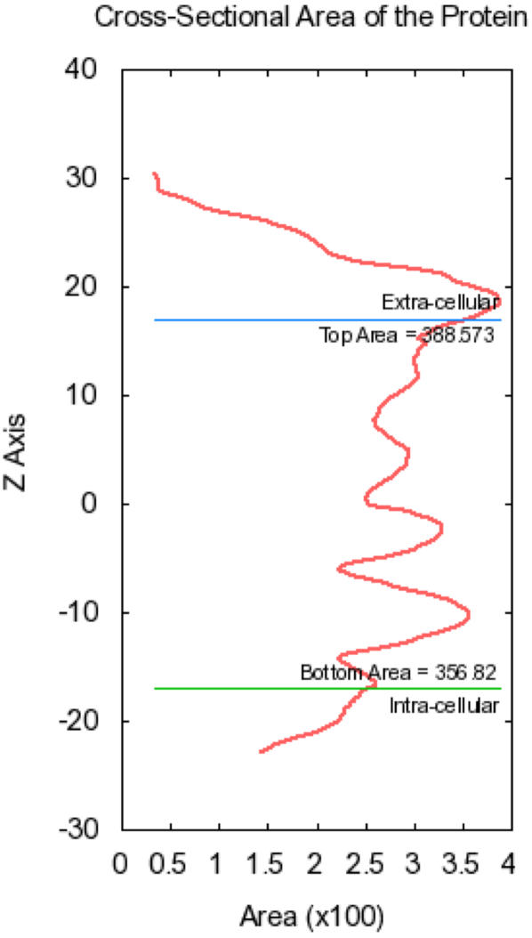
After alignment, Membrane Builder generates pore water, if specified, and calculates the protein cross-sectional area along the Z-axis. We have developed a new method to generate water molecules inside pores with any kind of shapes and numbers (see Pore Water Generation for details). The cross-sectional area profile is used to determine protein areas that correspond to the maximum values at 10 Å<Z<20 Å and −20 Å<Z<−10 Å, respectively. Figure 2 shows the calculated profile for PDB:2HAC (ζ-ζ transmembrane dimer). The protein areas in the top and bottom lipid leaflets are used to determine the system size in the next step. The cross-sectional area of pore water, if generated, is incorporated into the protein area so that the system size in the XY plane is determined as the sum of the protein area and the lipid area (see below).
Figure 2. Cross-sectional area profile of PDB:2HAC along the Z-axis.
Step 3–Determine System Size
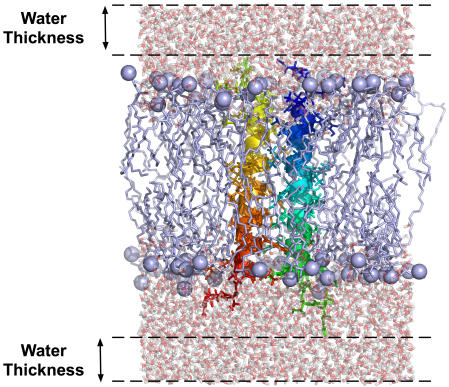
There are currently three types of lipid molecules available to build homogenous lipid bilayers, such as DMPC (experimental cross-sectional area of 60.7 Å2 at 303 K), DPPC (64.0 Å2 at 323 K), and POPC (68.3 Å2 at 303 K) [26]. By using the protein areas determined in the previous step and the experimental cross-sectional areas of lipid molecules, one can estimate the number of lipid molecules to build a system with specific dimension and shape (rectangular or hexagonal) in the XY plane, or vice versa. Membrane Builder facilitates this process by determining the system size based on users' inputs for (1) number of lipid layers, (2) number of lipid molecules, or (3) system dimensions. The number of lipid layers corresponds to the number of lipid molecules from a protein to the closest system edge so that this option can be used to quickly estimate the total number of lipid molecules. For example, “1.5 lipid layers” means, at least, three lipid molecules will be placed between two proteins in the primary and image systems. The system size along the Z-axis is determined by specifying the thickness of bulk water from the protein extent along the Z-axis, as shown in Fig. 3. In the case of membrane interfacial proteins whose extents do not cover the lipid bilayer, a minimum protein extent is set to Z = 20 Å and Z = −20 Å.
Figure 3. Thickness of bulk water from the protein extent (PDB:2HAC) along the Z-axis.
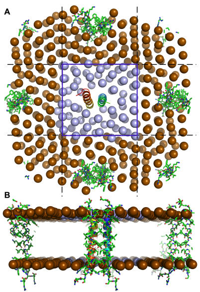
After the system size determination is completed, Membrane Builder provides a detailed summary of determined system size and a possible lipid-packing image to help users to check if the system size is proper. Figure 4 shows a packing image of PDB:2HAC, which corresponds to a configuration generated by MD simulations of lipid-like pseudo atoms whose cross-sectional area is similar to the lipid molecule. The image systems are also displayed to provide a better idea about the system size. If the system is smaller or larger than expected, users can go back and specify the numbers of lipid molecules (option 2) or system dimensions (option 3) to enlarge or reduce the system size.
Figure 4. Packing image with lipid-like pseudo atoms around PDB:2HAC.
An option of 1.5 lipid layer was used to estimate the number of lipid molecules. Both primary (blue region) and image systems (yellow region) in XY plane are visualized to provide a general idea about the lipid packing in the protein/membrane complex.
Step 4–Build Components
Based on the system size information, Membrane Builder generates individual components to fully solvate the protein, such as a lipid bilayer, bulk water, and counter ions. If pore water molecules were generated in Step 2, users can refine them in this step to make sure that there is no water molecule left outside of the protein in the membrane hydrophobic core region (see Pore Water Generation for details). If the ion concentration (C) is specified, the numbers of KCl ions (N K and N Cl) are determined by the ion-accessible volume (V) and the total charge of the system (Q sys), i.e., N K = C·V−Q sys/2 and N Cl = C·V+Q sys/2, to neutralize the system charge. The initial configuration of ions is then determined through Monte Carlo simulations using a primitive model, i.e., scaled Coulombic and van der Waals interactions. Note that only monovalent K and Cl ions are currently available, but more ion types can be incorporated easily upon users' request. It is this step that users select the lipid bilayer generation method, i.e., the insertion method or the replacement method (see below for details).
Step 5, 6–Assemble Components and equilibrate the system
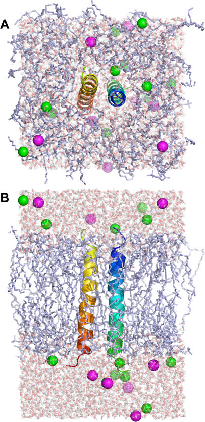
Each component that has been generated in the previous step will be assembled in this step as shown in Fig. 5. One of the most significant advantages of using the web environment is that, if a problem is found, users can go back and re-generate the whole system again before quitting the browser. Therefore, the visualization of the initially assembled structure is important to verify if the system is reasonable.
Figure 5. Assembled PDB:2HAC/DMPC structures with water thickness of 10 Å (see Figure 3) and 0.15 M of KCl.
(A) top and (B) side views. Green and magenta spheres represent chloride and potassium ions, respectively.
After the protein/membrane complex is assembled, the equilibration must be performed to relax the uncorrelated initial system before MD production simulations. However, due to the significant amount of computing power that cannot be hosted in our server, Membrane Builder provides six consecutive CHARMM input files for equilibration, which can be modified for continual production simulations. As shown in Table 1, to assure gradual equilibration of the initially assembled system, various restraints are applied to the protein, water, ions, and lipid molecules during the equilibration [27]: (1) harmonic restraints to ions and heavy atoms of the protein, (2) repulsive planar restraints to prevent water from entering into the membrane hydrophobic region, and (3) planar restraints to hold the position of head groups of membranes along the Z-axis. These restraint forces are slowly reduced as the equilibration progresses. To warrant the successful equilibration, i.e., to avoid instability of dynamics integrations during equilibration, the NVT dynamics (constant volume and temperature) is used for the first and second steps, and the NPAT (constant pressure, area, and temperature) dynamics for the rest at 303.15 K (DMPC and POPC) and 323.15 K (DPPC).
Table 1. Detailed information on each equilibration step.
| Step | Ensemble1 | Timesteps | Equilibration Time | Force Constants for Harmonic Restraint2 | ||||
| Protein Backbone3 | Protein Sidechain3 | Water4 | Lipid5 | Ion3 | ||||
| 1 | NVT | 1 fs | 25 ps | 10.0 | 5.0 | 2.5 | 2.5 | 10.0 |
| 2 | NVT | 1 fs | 25 ps | 5.0 | 2.5 | 2.5 | 2.5 | 0.0 |
| 3 | NPAT | 1 fs | 25 ps | 2.5 | 1.0 | 1.0 | 1.0 | 0.0 |
| 4 | NPAT | 2 fs | 100 ps | 1.0 | 0.5 | 0.5 | 0.5 | 0.0 |
| 5 | NPAT | 2 fs | 100 ps | 0.5 | 0.1 | 0.1 | 0.1 | 0.0 |
| 6 | NPAT | 2 fs | 100 ps | 0.1 | 0.0 | 0.0 | 0.0 | 0.0 |
NVT stands for constant volume and temperature, and NPAT for constant pressure, area, and temperature.
Force constants are in kcal/(mol·Å2).
Positional harmonic restraints.
Harmonic restraints to keep water molecules away from the membrane hydrophobic region.
Harmonic restraints to keep the lipid tail in –5 Å<Z<5 Å, and lipid head groups close to the membrane surface (Z = ±17 Å for DMPC and Z = ±19 Å for DPPC and POPC).
Lipid Bilayer Building Methods: Insertion and Replacement
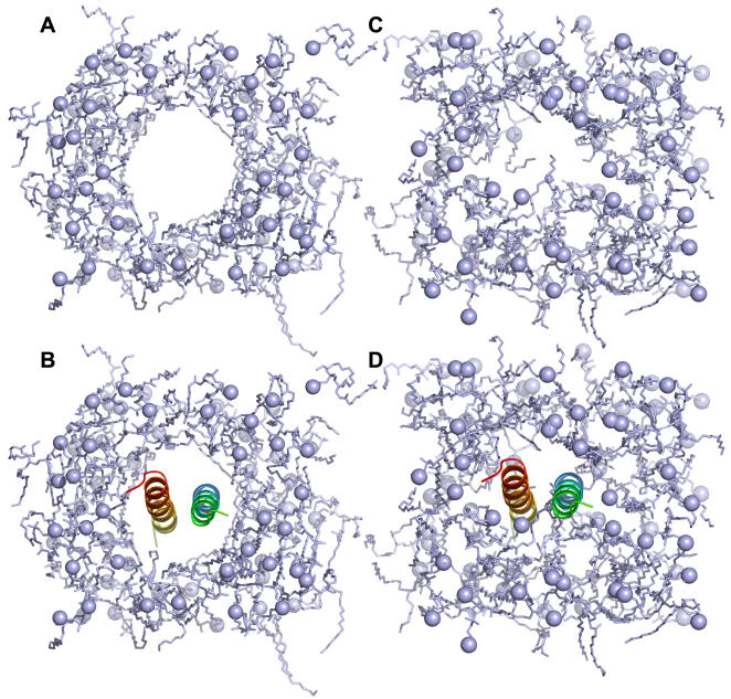
To generalize and automate the lipid bilayer building method, we have extended and further refined both insertion and replacement methods. Figure 6 shows a clear distinction between insertion and replacement methods. The insertion method creates a hole in a bilayer by applying weak repulsive radial forces during the simulation of the lipid bilayer, and insert a protein into the hole, as shown in Figs. 6A and 6B. By utilizing a library that has various sizes of holes in pre-equilibrated lipid bilayers, the insertion method can generate a lipid bilayer less than a minute. Currently, a library for each lipid molecule (DMPC, DPPC, and POPC) is composed of 90 pre-equilibrated lipid bilayers with a hole of radius from 1 Å to 45 Å for two different number of lipid molecules (128 or 256 lipid molecules) (see Materials and Methods for details). The size of the largest lipid bilayer is 90 Å by 90 Å in the XY plane with 256 lipid molecules (128 for each leaflet). Therefore, if a system dimension is larger than 90 Å by 90 Å in XY, or the number of lipid molecules in one leaflet is more than 128, Membrane Builder will ask users to select the replacement method. By assuming that the protein has a cylindrical shape, the hole sizes are first estimated from the protein areas in the top and bottom lipid leaflets. Then, the top and bottom lipid leaflets with the estimated hole sizes are selected from the library and the numbers of lipid molecules are reduced to their target numbers determined in Step 3. Therefore, the insertion method is useful for a protein that has a regular and cylindrical shape. Otherwise, the replacement method would be a better choice.
Figure 6. DMPC lipid bilayers generated by (A and B) the insertion method and (C and D) the replacement method for PDB:2HAC.
The replacement method distributes lipid-like pseudo atoms around the protein, and substituting each atom with a lipid molecule that is randomly selected from a lipid molecular library. In Membrane Builder, the library is composed of 2,000 different conformations that were gathered from MD simulations of pure lipid bilayers (see Materials and Methods for details). Figure 6D shows a DMPC lipid bilayer generated by the replacement method for PDB:2HAC. Unlike the insertion method, lipid molecules wrap around the protein such that the replacement method can be used for virtually any kinds of membrane proteins, including transmembrane proteins, monotopic proteins, and interfacial peptides. Furthermore, this method should be able to generate a mixed lipid bilayer with slight modification in the lipid substitution process.
There are limitations and advantages in each method. The insertion method can build a lipid bilayer quickly, and the generated lipid bilayer is pre-equilibrated. However, the insertion method has a couple of limitations related to the system size and the protein shape. On the other hand, the replacement method can generate a lipid bilayer for virtually any kinds of shape and size of membrane proteins. However, it takes more time to generate a lipid bilayer, e.g., 5 to 50 minutes depending on the system size, and the generated bilayer is not pre-equilibrated. The library of lipid bilayers with holes and the library of lipid molecules for each lipid type are freely available at the archive on the CHARMM-GUI website.
Pore Water Generation
Ion channels, transporters, and porins have pores that are large enough to accommodate water molecules. A traditional way of generating the so-called pore water is to build a cylindrical water box, place the box inside the pore, and remove water molecules that overlap with the protein. It is easy to implement and works well for some cases. During the tests of Membrane Builder, however, we have encountered many cases that the traditional method cannot be applied directly. For example, a closed form of mechanosensitive channel (PDB:2OAR) has a pore opened only half of the transmembrane region, and the cross-sectional area profile varies markedly. If the pore were filled by the traditional method, large number of water molecules would be left in the protein exterior near the closed region of the protein. Another example is bacterial porins (e.g., PDB:1PHO) with three pores, so that it is not conceivable to fill the pores automatically with the traditional method.
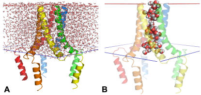
In order to make the generation process of pore water more general and persuasive, we have developed a new method based on a simple idea that water molecules inside the pore would remain while those outside of the protein would evaporate during a high temperature dynamics. As shown in Table 1, water molecules can access to the pore vestibules in the lipid head group regions, but not into the hydrophobic region due to the restraints for water during equilibration. Therefore, Membrane Builder only solvates the transmembrane region, as shown in Fig. 7A, and runs molecular dynamics at a high temperature (5,000 K) with protein fixed and planar restraint potentials on the top and bottom of the water box to keep pore water molecules in the transmembrane region. Most water molecules that are outside of the protein are quickly removed after a couple of dynamics cycles, as shown in Fig. 7B. However, it is conceivable that a few water molecules may stay near the protein exterior if they interact with protein strongly. To resolve this problem, we have introduced the refinement step of pore water generation in Step 4 to remove those water molecules interactively by selecting residue numbers of water molecules after users' visual inspection. Users can verify this step by visualizing the pore region again after removing selected water molecules.
Figure 7. Pore water generation.
(A) The transmembrane region of the protein is solvated with a waterbox. (B) Only pore water molecules had remained after pore water generation through high-temperature dynamics.
Test cases
In order to illustrate and verify the efficiency and applicability of the web-based Membrane Builder, we have generated the protein/membrane complexes for 15 membrane proteins of various sizes and shapes, 12 transmembrane and 3 interfacial proteins (see Table 2). Three kinds of lipid molecules (DMPC, DPPC, and POPC) and two kinds of system shapes (rectangular and hexagonal) were used to build a total of 90 complex systems. The test was facilitated by using pre-oriented protein structures from OPM database [25] and the default values in each step, i.e., 1.5 lipid layers to determine the system size in XY, 12 Å water thickness to determine the system size along Z, and 0.15 M KCl concentration (the physiological ion concentration), unless specified explicitly. It should be stressed that these default values were elaborated and tested extensively by building the large number of protein/membrane complexes. Table 2 shows the detailed information on the systems with POPC membranes and the full list of 90 complex systems is shown in Table S1 in the Supporting Information. Note that ligands such as ions or small molecules in original PDB structures are not included.
Table 2. Testcases and system information with POPC membranes.
| PDB ID | System Shape1 | Numbers of Each Components | Total Atoms | System Size2 | |||
| Lipid | H2O | K+ | Cl− | ||||
| 1GZM3 | rect | 110 | 9,173 | 30 | 25 | 47,523 | 67×74×99 |
| hexa | 79 | 6,713 | 24 | 19 | 35,977 | 67×67×99 | |
| 2OAR3 | rect | 141 | 16,056 | 48 | 48 | 77,651 | 84×84×112 |
| hexa | 112 | 13,582 | 41 | 41 | 66,329 | 84×84×112 | |
| 1ZLL3 | rect | 194 | 12,640 | 27 | 47 | 68,653 | 89×89×89 |
| hexa | 164 | 10,544 | 22 | 42 | 58,335 | 90×90×89 | |
| 1I783 | rect | 98 | 8,174 | 17 | 23 | 44,811 | 65×65×102 |
| hexa | 86 | 7,357 | 25 | 20 | 38,222 | 66×66×102 | |
| 2GFP3 | rect | 130 | 8,635 | 20 | 26 | 49,106 | 80×75×80 |
| hexa | 116 | 7,946 | 18 | 24 | 45,159 | 80×80×80 | |
| 1OKC3 | rect | 125 | 7,594 | 14 | 31 | 35,605 | 75×75×82 |
| hexa | 95 | 5,960 | 10 | 27 | 44,535 | 73×73×82 | |
| 1UYN3 | rect | 103 | 7,995 | 22 | 21 | 42,011 | 67×67×91 |
| hexa | 87 | 6,601 | 20 | 19 | 35,681 | 67×67×91 | |
| 1H2S4 | rect | 183 | 14,333 | 42 | 36 | 76,217 | 108×77×90 |
| hexa | 237 | 17,772 | 50 | 44 | 93,786 | 108×108×90 | |
| 1SU44 | rect | 452 | 62,760 | 178 | 151 | 264,614 | 130×130×147 |
| hexa | 386 | 53,969 | 156 | 129 | 229,353 | 130×130×147 | |
| 1UUN4 | rect | 227 | 44,526 | 168 | 80 | 214,653 | 130×130×120 |
| hexa | 187 | 37,970 | 151 | 63 | 185,973 | 130×130×120 | |
| 2A654 | rect | 303 | 26,082 | 69 | 75 | 135,400 | 115×122×95 |
| hexa | 227 | 21,070 | 56 | 62 | 110,154 | 115×115×95 | |
| 1XQ84 | rect | 243 | 8,334 | 18 | 22 | 58,978 | 75×119×64 |
| hexa | 341 | 11,493 | 25 | 29 | 81,601 | 119×119×64 | |
| 2DEO4 | rect | 158 | 10,367 | 29 | 29 | 55,447 | 70×80×95 |
| hexa | 156 | 10,356 | 29 | 29 | 55,146 | 80×80×95 | |
| 1D5R4 | rect | 274 | 18,867 | 47 | 58 | 98,539 | 100×100×97 |
| hexa | 235 | 16,288 | 40 | 51 | 85,562 | 100×100×97 | |
| 1PHO4 | rect | 230 | 17,835 | 63 | 33 | 101,695 | 112×112×82 |
| hexa | 188 | 15,726 | 58 | 28 | 89,730 | 113×113×82 | |
The system shape in the XY plane: rect for rectangular and hexa for hexagonal.
The system size (in Å) is given by L X×L Y×L Z, where L X, L Y, and L Z correspond the lengths of the system along the X, Y, and Z axes, respectively. In the case of hexagonal systems, L X ( = L Y) corresponds to the length of the longest diagonal.
The insertion method was used to build protein/membrane complex systems.
The replacement method was used to build protein/membrane complex systems.
For given testcases, the whole process of generating a protein/membrane system took 5 minutes to 2 hours depending on the system size. The smallest protein and the largest protein in the testcases are PDB:1UYN (translocation domain of autotransporter NalP) and PDB:1SU4 (calcium ATPase), respectively. We have applied the insertion method for the proteins that have a cylindrical and regular shape, such as PDB:1GZM (bovine rhodopsin), 1ZLL (human phospholamban pentamer), 1I78 (outer membrane protease OmpT), 2GFP (multidrug transporter EmrD), 1OKC (mitochondrial ADP/ATP carrier), 2OAR (mechanosensitive channel of large conductance), 1UYN (translocator domain of autotransporter NalP). The replacement method was used for the other proteins that have rather irregular shape, including interfacial peptides, such as PDB:1H2S (sensory rhodopsin II), 2A65 (a bacterial homolog of Na+/Cl− dependent neurotransmitter transporters), 1SU4 (calcium ATPase), 1PHO (E. Coli porins), 1XQ8 (human micelle-bound alpha-synuclein), 2DEO (membrane protease specific for a stomatin homolog from Pyrococcus horikoshii), PDB:1UUN (main porin from Mycobacteria), and 1D5R (PTEN tumor suppressor). Pore water molecules were generated for PDB:2OAR, 1I78, 1OKC, 1UYN, 1UUN and 1ZLL. There are three membrane proteins such as PDB:1SU4, 1UUN, and 1XQ8 for which the default options could not generate the complex system properly. Both PDB:1SU4 and 1UUN have soluble cellular domains that are much larger than their transmembrane domain. Since Membrane Builder determines the system size in XY only based on the size of the transmembrane domain, the system size generated by the default “1.5 lipid layers” was not big enough to accommodate the cellular domain. Therefore, we had to manually adjust their system size. Since the final system size of PDB:1UUN was too big to use the insertion method, we had to use the replacement method, although it has a cylindrical and regular shape. In particular, PDB:1XQ8 has a very elongated conformation along the membrane surface. Since Membrane Builder assumes that the protein shape in the XY plane is more or less symmetric, the estimated system size by the default values was much smaller than it should be, such that we had to adjust the system size manually.
Each system was equilibrated for 375 ps in our local machines using the equilibration input files that were generated by Membrane Builder (see Table 1). All the calculations were performed with CHARMM [28], and the all-atom parameter set PARAM22 for proteins [29] including dihedral cross-term corrections (CMAP) [30] and a modified TIP3P water model [31], as well as recently optimized lipid parameters [32]. The NVT dynamics (constant volume and temperature) is used for the first and second steps, and the NPAT (constant pressure, area, and temperature) dynamics for the rest at 303.15K (DMPC and POPC) and 323.15K (DPPC). The equilibrated protein/membrane complexes are freely available at the archive on the CHARMM-GUI website.
Discussion
We have described the generalized and automated process to build a protein/membrane complex interactively and easily using Membrane Builder in the CHARMM-GUI website. Its efficacy was illustrated by building protein/membrane complexes for 15 membrane proteins of various sizes and shapes. Each and every step is translated into a web interface so that a realistic protein/membrane complex can be generated through a web browser with a graphical user interface. The significance of this work is that the web interface provides not only the intuitive and elegant way to generate the membrane system, but also the detailed input files that are already optimized and tested extensively. We have adopted and further developed two lipid bilayer generation methods, “replacement method” and “insertion method.” The insertion method uses a pre-equilibrated lipid bilayer with a hole of an appropriate size into which a protein is inserted. This method is particularly useful for a protein with cylindrical and symmetrical shape. If a protein has an irregular shape, the replacement method would be a better choice. The replacement method uses a packing of lipid-like pseudo atoms, and replaces them by lipid molecules one at a time. Therefore, it generates a nicely packed lipid bilayer around the protein.
While Membrane Builder currently supports three types of lipid molecules such as DMPC, DPPC, and POPC, we will make more lipid molecules available by generating the necessary lipid libraries. In addition, we will incorporate a method of building mixed lipid bilayers by introducing a step for choosing different types of lipids randomly in the replacement method. Furthermore, Membrane Builder will provide the CPγT (constant pressure, surface tension, and temperature) dynamics [33] to allow the system size along the X and Y axes to vary during the simulation, and the P21 image transformation [34] to allow the number of lipid molecules in the top and bottom leaflets to vary during the simulation. Although Membrane Builder has been developed to use CHARMM [28] as a MD simulation engine, we will provide the equilibration input files for other MD software such as GROMACS [35] and NAMD [36] in near future so that users can continue the equilibration of the generated membrane system with their own MD software.
Materials and Methods
Lipid Bilyaer Library and Lipid Molecule Library
To facilitate the building process of a membrane bilayer using the insertion and replacement methods, the library of lipid bilayers with holes and the library of lipid molecules have been generated. There are 90 pre-equilibrated lipid bilayers with a hole of radius from 1 Å to 45 Å for two different number of lipid molecules (128 or 256 lipid molecules) in the lipid library for DMPC, DPPC, and POPC. Starting from an equilibrated membrane bilayer of each type of lipid, the cylindrical pore has been generated by increasing the pore radius by 1 Å every 50 ps with a cylindrical harmonic restraint at 303.15 K (DMPC and POPC) and at 323.15 K (DPPC). The maximum number of lipid molecules available in each lipid bilayer is 256 (128 for each leaflet), and the largest bilayer size is 90 Å by 90 Å. The lipid molecule library for each type of lipid contains 2,000 different conformations. Lipid molecules are randomly selected from a 2.5 ns trajectory of each lipid bilayer. All the calculations were performed with CHARMM [28], and the all-atom parameter set PARAM22 for proteins [29] including dihedral cross-term corrections (CMAP) [30] and a modified TIP3P water model [31], as well as recently optimized lipid parameters [32].
Supporting Information
(0.23 MB DOC)
Acknowledgments
We thank Jeffery Klauda, Patrick Lague, and Richard Pastor for providing equilibrated DMPC, DPPC, and POPC lipid coordinate. Sunhwan Jo is the recipient of the Undergraduate Research Assistant Fund from The University of Kansas.
Footnotes
Competing Interests: The authors have declared that no competing interests exist.
Funding: This work was supported by institutional funding from The University of Kansas.
References
- 1.Jordan JD, Landau EM, Iyengar R. Signaling networks: the origins of cellular multitasking. Cell. 2000;103:193–200. doi: 10.1016/s0092-8674(00)00112-4. [DOI] [PMC free article] [PubMed] [Google Scholar]
- 2.Hunter T. Signaling–2000 and beyond. Cell. 2000;100:113–127. doi: 10.1016/s0092-8674(00)81688-8. [DOI] [PubMed] [Google Scholar]
- 3.Fu D, Libson A, Miercke LJ, Weitzman C, Nollert P, et al. Structure of a glycerol-conducting channel and the basis for its selectivity. Science. 2000;290:481–486. doi: 10.1126/science.290.5491.481. [DOI] [PubMed] [Google Scholar]
- 4.Khademi S, O'Connell J, 3rd, Remis J, Robles-Colmenares Y, Miercke LJ, et al. Mechanism of ammonia transport by Amt/MEP/Rh: structure of AmtB at 1.35 A. Science. 2004;305:1587–1594. doi: 10.1126/science.1101952. [DOI] [PubMed] [Google Scholar]
- 5.Yellen G. The voltage-gated potassium channels and their relatives. Nature. 2002;419:35–42. doi: 10.1038/nature00978. [DOI] [PubMed] [Google Scholar]
- 6.Jiang Y, Lee A, Chen J, Cadene M, Chait BT, et al. Crystal structure and mechanism of a calcium-gated potassium channel. Nature. 2002;417:515–522. doi: 10.1038/417515a. [DOI] [PubMed] [Google Scholar]
- 7.Murata K, Mitsuoka K, Hirai T, Walz T, Agre P, et al. Structural determinants of water permeation through aquaporin-1. Nature. 2000;407:599–605. doi: 10.1038/35036519. [DOI] [PubMed] [Google Scholar]
- 8.Dong J, Yang G, McHaourab HS. Structural basis of energy transduction in the transport cycle of MsbA. Science. 2005;308:1023–1028. doi: 10.1126/science.1106592. [DOI] [PubMed] [Google Scholar]
- 9.Elston T, Wang H, Oster G. Energy transduction in ATP synthase. Nature. 1998;391:510–513. doi: 10.1038/35185. [DOI] [PubMed] [Google Scholar]
- 10.Alberts B. New York: Garland Science; 2002. Molecular biology of the cell. p. xxxiv, 1463, [1486]. [Google Scholar]
- 11.Wallin E, von Heijne G. Genome-wide analysis of integral membrane proteins from eubacterial, archaean, and eukaryotic organisms. Protein Sci. 1998;7:1029–1038. doi: 10.1002/pro.5560070420. [DOI] [PMC free article] [PubMed] [Google Scholar]
- 12.Terstappen GC, Reggiani A. In silico research in drug discovery. Trends Pharmacol Sci. 2001;22:23–26. doi: 10.1016/s0165-6147(00)01584-4. [DOI] [PubMed] [Google Scholar]
- 13.White S Membrane Proteins of Known 3D Structure. http://blanco.biomol.uci.edu/Membrane_Proteins_xtal.html. [Google Scholar]
- 14.Berman HM, Battistuz T, Bhat TN, Bluhm WF, Bourne PE, et al. The Protein Data Bank. Acta Crystallogr D Biol Crystallogr. 2002;58:899–907. doi: 10.1107/s0907444902003451. [DOI] [PubMed] [Google Scholar]
- 15.de Groot BL, Grubmuller H. Water permeation across biological membranes: mechanism and dynamics of aquaporin-1 and GlpF. Science. 2001;294:2353–2357. doi: 10.1126/science.1066115. [DOI] [PubMed] [Google Scholar]
- 16.Chakrabarti N, Tajkhorshid E, Roux B, Pomes R. Molecular basis of proton blockage in aquaporins. Structure. 2004;12:65–74. doi: 10.1016/j.str.2003.11.017. [DOI] [PubMed] [Google Scholar]
- 17.Roux B, Schulten K. Computational studies of membrane channels. Structure. 2004;12:1343–1351. doi: 10.1016/j.str.2004.06.013. [DOI] [PubMed] [Google Scholar]
- 18.Noskov SY, Berneche S, Roux B. Control of ion selectivity in potassium channels by electrostatic and dynamic properties of carbonyl ligands. Nature. 2004;431:830–834. doi: 10.1038/nature02943. [DOI] [PubMed] [Google Scholar]
- 19.Petrache HI, Grossfield A, MacKenzie KR, Engelman DM, Woolf TB. Modulation of glycophorin A transmembrane helix interactions by lipid bilayers: molecular dynamics calculations. J Mol Biol. 2000;302:727–746. doi: 10.1006/jmbi.2000.4072. [DOI] [PubMed] [Google Scholar]
- 20.Woolf TB, Roux B. Molecular dynamics simulation of the gramicidin channel in a phospholipid bilayer. Proc Natl Acad Sci U S A. 1994;91:11631–11635. doi: 10.1073/pnas.91.24.11631. [DOI] [PMC free article] [PubMed] [Google Scholar]
- 21.Woolf TB, Roux B. Structure, energetics, and dynamics of lipid-protein interactions: A molecular dynamics study of the gramicidin A channel in a DMPC bilayer. Proteins. 1996;24:92–114. doi: 10.1002/(SICI)1097-0134(199601)24:1<92::AID-PROT7>3.0.CO;2-Q. [DOI] [PubMed] [Google Scholar]
- 22.Shen L, Bassolino D, Stouch T. Transmembrane helix structure, dynamics, and interactions: multi-nanosecond molecular dynamics simulations. Biophys J. 1997;73:3–20. doi: 10.1016/S0006-3495(97)78042-1. [DOI] [PMC free article] [PubMed] [Google Scholar]
- 23.Tieleman DP, Berendsen HJ. A molecular dynamics study of the pores formed by Escherichia coli OmpF porin in a fully hydrated palmitoyloleoylphosphatidylcholine bilayer. Biophys J. 1998;74:2786–2801. doi: 10.1016/S0006-3495(98)77986-X. [DOI] [PMC free article] [PubMed] [Google Scholar]
- 24.Faraldo-Gomez JD, Smith GR, Sansom MS. Setting up and optimization of membrane protein simulations. Eur Biophys J. 2002;31:217–227. doi: 10.1007/s00249-002-0207-5. [DOI] [PubMed] [Google Scholar]
- 25.Lomize MA, Lomize AL, Pogozheva ID, Mosberg HI. OPM: orientations of proteins in membranes database. Bioinformatics. 2006;22:623–625. doi: 10.1093/bioinformatics/btk023. [DOI] [PubMed] [Google Scholar]
- 26.Nagle JF, Tristram-Nagle S. Structure of lipid bilayers. Biochim Biophys Acta. 2000;1469:159–195. doi: 10.1016/s0304-4157(00)00016-2. [DOI] [PMC free article] [PubMed] [Google Scholar]
- 27.Im W, Roux B. Ions and counterions in a biological channel: a molecular dynamics simulation of OmpF porin from Escherichia coli in an explicit membrane with 1 M KCl aqueous salt solution. J Mol Biol. 2002;319:1177–1197. doi: 10.1016/S0022-2836(02)00380-7. [DOI] [PubMed] [Google Scholar]
- 28.Brooks BR, Bruccoleri RE, Olafson BD, States DJ, Swaminathan S, et al. CHARMM: a program for macromolecular energy, minimization, and dynamics calculations. J Comp Chem. 1983;4:187–217. [Google Scholar]
- 29.MacKerell AD, Bashford D, Bellott M, Dunbrack RL, Evanseck JD, et al. All-atom empirical potential for molecular modeling and dynamics studies of proteins. Journal of Physical Chemistry B. 1998;102:3586–3616. doi: 10.1021/jp973084f. [DOI] [PubMed] [Google Scholar]
- 30.Mackerell AD, Jr, Feig M, Brooks CL., 3rd Extending the treatment of backbone energetics in protein force fields: limitations of gas-phase quantum mechanics in reproducing protein conformational distributions in molecular dynamics simulations. J Comput Chem. 2004;25:1400–1415. doi: 10.1002/jcc.20065. [DOI] [PubMed] [Google Scholar]
- 31.Jorgensen WL, Chandrasekhar J, Madura JD, Impey RW, Klein ML. Comparison of Simple Potential Functions for Simulating Liquid Water. Journal of Chemical Physics. 1983;79:926–935. [Google Scholar]
- 32.Klauda JB, Brooks BR, MacKerell AD, Venable RM, Pastor RW. An ab initio study on the torsional surface of alkanes and its effect on molecular simulations of alkanes and a DPPC bilayer. Journal of Physical Chemistry B. 2005;109:5300–5311. doi: 10.1021/jp0468096. [DOI] [PubMed] [Google Scholar]
- 33.Feller SE, Zhang YH, Pastor RW. Computer-Simulation of Liquid/Liquid Interfaces .2. Surface-Tension Area Dependence of a Bilayer and Monolayer. Journal of Chemical Physics. 1995;103:10267–10276. [Google Scholar]
- 34.Dolan EA, Venable RM, Pastor RW, Brooks BR. Simulations of membranes and other interfacial systems using P2(1) and Pc periodic boundary conditions. Biophys J. 2002;82:2317–2325. doi: 10.1016/S0006-3495(02)75577-X. [DOI] [PMC free article] [PubMed] [Google Scholar]
- 35.Van Der Spoel D, Lindahl E, Hess B, Groenhof G, Mark AE, et al. GROMACS: fast, flexible, and free. J Comput Chem. 2005;26:1701–1718. doi: 10.1002/jcc.20291. [DOI] [PubMed] [Google Scholar]
- 36.Phillips JC, Braun R, Wang W, Gumbart J, Tajkhorshid E, et al. Scalable molecular dynamics with NAMD. J Comput Chem. 2005;26:1781–1802. doi: 10.1002/jcc.20289. [DOI] [PMC free article] [PubMed] [Google Scholar]
Associated Data
This section collects any data citations, data availability statements, or supplementary materials included in this article.
Supplementary Materials
(0.23 MB DOC)


