

Abstract
To date, there have been a number of cases where glucose sensors have performed well over long periods of implantation; however, it remains difficult to predict whether a given sensor will perform reliably, will exhibit gradual degradation of performance, or will fail outright soon after implantation. Typically, the literature emphasizes the sensor that performed well, while only briefly (if at all) mentioning the failed devices. This leaves open the question of whether current sensor designs are adequate for the hostile in vivo environment, and whether these sensors have been assessed by the proper regimen of testing protocols. This paper reviews the current in vitro and in vivo testing procedures used to evaluate the functionality and biocompatibility of implantable glucose sensors. An overview of the standards and regulatory bodies that govern biomaterials and end-product device testing precedes a discussion of up-to-date invasive and non-invasive technologies for diabetes management. Analysis of current in vitro, in vivo, and then post implantation testing is presented. Given the underlying assumption that the success of the sensor in vivo foreshadows the long-term reliability of the sensor in the human body, the relative merits of these testing methods are evaluated with respect to how representative they are of human models.
1. Background
Within the United States, 20.8 million people (7% of population) have diabetes [1] Approximately $132 billion is spent annual on direct and indirect costs relating to diabetes [2]. Over 200 000 Americans die each year from this chronic disease, making diabetes the sixth leading cause of death in the United States [1]. Diabetic individuals are at a greater risk heart disease, stroke, high blood pressure, blindness, kidney failure, neurological disorders and other health related complications without diligent monitoring blood glucose concentrations [1, 3]. Through patient education, regular examinations and tighter blood glucose monitoring, many of these complications can be reduced significantly [1, 4].
The American Diabetes Association recommends that insulin-dependent type 1 diabetics self-monitor blood glucose 3–4 times daily, while insulin-dependent type 2 diabetics monitor once-daily [5]. Yet, intensive control through frequent self-monitoring of glucose concentrations is difficult, given the time, the inconvenience and the discomfort involved with the traditional “finger prick” technique [6]. It is estimated that only 30% of type 1 diabetics and 20% of type 2 diabetics who take insulin monitor their blood glucose levels more than once daily [7].
The danger of rapid hypoglycemic episodes, the long term health ramifications caused by inadequate glycemic control, and the reality of insufficient patient compliance to frequent blood testing, argues strongly for continuous glucose monitoring systems. Technologies for glucose monitoring can be categorized into invasive and non-invasive approaches. Figure 1 outlines several invasive and non-invasive methods available or being developed for diabetes management.
Figure 1.
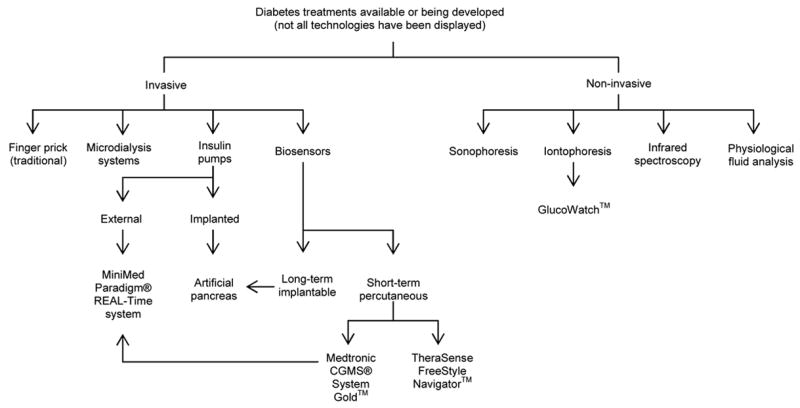
Outline of several diabetic treatments currently available or being developed.
Non-invasive approaches have generated considerable excitement. Fischer [8] and Wilkins et al [9] provide excellent reviews of the main non-invasive approaches being pursued for glucose sensor development: infrared spectroscopy, excreted physiological fluid (tears, sweat, urine, saliva) analysis, microcalorimetry, enzyme electrodes and optical sensors. A more recent review by Gabbay [10] outlines several additional non-invasive methods for monitoring blood glucose levels, including sonophoresis and iontophoresis, both of which extract glucose from the skin.
The commercially available GlucoWatch™ (Cygnus, Redwood City, CA) utilizes iontophoresis technology to measure the glucose concentrations of diabetic individuals. Ions present in the skin are drawn to the cathode and anode contained in the GlucoWatch™ as a low-level electric current is passed through the skin. Interstitial glucose is transported along with the ions to the surface of the skin, where the glucose is detected by an amperometric biosensor and the measured glucose concentration is displayed by the watch [11]. This watch, worn on the wrist, has a built-in audible alarm to alert the wearer when glucose levels deviate significantly from the normal blood glucose range [11, 12]. This device greatly increases the frequency of blood glucose monitoring over the course of a day compared to the monitoring performed by individuals using the finger-prick technique. In 2004, 20 000 GlucoWatch™ devices were in use within the United States and abroad [13].
Recently, Medtronic (Minneapolis, Minnesota) launched the new MiniMed Paradigm® REAL-Time insulin pump and continuous glucose monitoring system that uses wireless technology to transmit calculated blood glucose concentrations from the light-weight transmitter attached to a subcutaneously implanted sensor to an external insulin pump. The Medtronic CGMS® System Gold™ Continuous Glucose Monitoring System is the only FDA approved implantable glucose sensor. The insulin pump Bolus Wizard™ calculator automatically recommends an appropriate insulin dosage, based on the transmitted information, which simplifies the math associated with calculating proper insulin dosages [14, 15]. This system reduces the chance of inaccurate insulin dosages that arise from mental mathematical miscalculations, thereby preventing erroneous blood sugar control. Currently, over 350 000 individuals worldwide use Medtronic MiniMed pumps, and the consumer demand for the REAL-Time continuous glucose monitoring kits is enthusiastic [16].
The TheraSense FreeStyle Navigator™ Continuous Glucose Sensor (Abbott Laboratories, Alameda, CA) is an electrochemical sensor, designed for subcutaneous use, that offers reduced oxygen dependency by incorporating an osmium (Os)-based mediator molecule into the sensor construct [17]. The lower operating potential of the sensor (+40 mV opposed to the −500mV required by most H2O2-sensing systems) minimizes the oxidation of many electroactive interfering molecules responsible for false high glucose readings. In vivo studies have demonstrated that sensors experience near negligible sensor drift and maintain consistent glucose sensitivity over a three day test period. A wireless system has been developed, that includes hypo- and hyperglycaemic alarms, trend analysis and real-time glucose data [18]. FDA approval on the Navigator™ is still pending [19]. Other continuous and invasive approaches undergoing development include microdialysis systems [9, 20, 21], micropore systems [22], and implantable biosensors [9, 23], the latter of which will be the focus of this paper.
Given the evolution of promising alternatives, why are amperometric glucose sensing methods still being researched? Despite the relative ease of use, speed and minimal risk of infection involved with infrared spectroscopy, this technique is hindered by the low sensitivity, poor selectivity, frequently required calibrations, and difficulties with miniaturization [8–10]. Problems surrounding direct glucose analysis through excreted physiological fluids include a weak correlation between excreted fluids and blood glucose concentrations. Exercise and diet that alter glucose concentrations in the fluids also produce inaccurate results [24].
The GlucoWatch™ and MiniMed Paradigm® REAL-Time system neither eliminate nor minimize the number of blood samples that must be collected using the finger-prick technique. Each time the GlucoWatch™ is worn, a blood glucose sample must be taken to calibrate the device. An additional calibration may be required if an individual exercises while wearing the watch, as excess sweat and rapid increase in skin temperature confound the measurements, causing the GlucoWatch™ to shut off [25]. According to the FDA, unpredictable variations in glucose measurements by the GlucoWatch™ requires that finger-prick tests be used to confirm results before changes in insulin dosage are made [24]. Mild skin irritation has also been reported from wearing the GlucoWatch™ [25].
The MiniMed Paradigm® REAL-Time insulin pump and continuous glucose monitoring system displays real-time glucose levels on the insulin pump every 5 minutes; however, only the cost of the insulin pump component of this system is covered by insurance companies. The continuous glucose monitoring system component is retailed at $1000 USD, and an additional $350 per month is required for supplies, none of which is reimbursed [26]. Despite the advantages of this system, the cost of the MiniMed Paradigm® REAL-Time insulin pump and continuous glucose monitoring system is often too high for most individuals. Clearly, the limitations of the current non-invasive methods emphasize the need to pursue research in alternative areas.
The desire to create an artificial pancreas is the Holy Grail for continued research efforts in the area of these biosensors [9]. The hope that a marketable artificial pancreas is on the horizon has been lingering for decades; however, progress is being made to this end [23]. Nevertheless, before such an insulin modulating system can be realized, issues surrounding in vivo biosensor reliability of the implanted sensor must be resolved [27, 28].
Previously, we have reviewed materials-tissue interactions specifically for sensors [27, 29–31]. To a large extent, sensor failure can be linked to the events associated with healing of the tissue surrounding the implanted device, such as hemostasis, inflammation, repair and encapsulation. A number of materials-based approaches have been taken to either circumvent or control this wound healing process with the goal of improving in vivo sensor performance. As reviewed by Wisniewski et al. [31], these can be divided into several strategies. From a materials processing perspective, most of these strategies fall under the rubric of chemically passive surface and/or thin film modifications; however, from a surface energy perspective, the applied films range from hydrophilic hydrogels, phospholipids-based polymers, proteins and sugars to hydrophobic Nafion, diamond-like carbon, and surfactants. It is hypothesized that surface-textured features can direct cell growth and thus influence the healing of the surrounding tissue, such as porosity-associated enhancement of angiogenesis [32–37]. Flow-based approaches are active because they employ fluid streaming to reduce cell adhesion and protein adsorption. Drug eluting [38] and gene delivery [39] approaches are also gaining attention as active surface modification strategies because of their ability to attenuate inflammation and/or stimulate angiogenesis.
Despite the range of surface chemistries, each approach is a candidate strategy because of their documented ability to affect protein adsorption and cell adhesion in vitro. However, these varied schemes have yielded mixed success in vivo. Particularly curious is the well documented observation that sensors which have failed in vivo frequently regain the ability to detect glucose once explanted and retested in vitro[40–46]. Consequently, a closer look into the tests used to assess sensor performance must accompany the development of materials-based strategies used to alleviate wound healing related modes of sensor failure. This paper presents a systematic review of in vitro, in vivo and post implantation sensor testing protocols required to fully understand the phenomena plaguing long-term sensor reliability.
2. Standards
Biocompatibility testing of an implantable glucose sensor should occur both in vitro and in vivo [47]. There are three main sources of standards for evaluating of biomaterials and end-product devices: the American Society for Testing and Materials (ASTM), the United States Pharmacopeia (USP) and the International Organization for Standardization (ISO). Guidelines are provided by ASTM, USP and ISO to assist investigators in deciding which specific tests should be performed to assure that the final product functions as intended, is safe for human use and uses as few animals as possible during the testing procedures.
Each regulatory body classifies medical devices based on the same criteria, which includes device category, placement on or in the body and duration of contact with the body. An implantable biosensor is classified as an implantable device that will contact body tissue or bone for more than 30 days [48–50]. Based on the classification of the device, the appropriate tests can be determined from a test selection matrix. Once identified from the matrix, the corresponding test standards should be identified and followed as outlined. A summary of the tests recommended for an implantable biosensor is provided in Table 1. These guidelines are in accordance with the device categories and suggested biological testing set forth by the Federal Drug Administration (FDA) [51].
Table 1.
Testing guidelines recommended by ISO, USP and ASTM for an implantable device that will contact the body tissue or bone for more than 30 days *.
| Regulatory Body | Recommended Standards |
|---|---|
| ISO |
Initial Evaluation Tests
Cytotoxicity ISO 10993-5: Tests for in-vitro cytotoxicity Sensitization ISO 10993-10: Tests for irritation and delay-type hypersensitivity Genotoxicity ISO 10993-3: Tests for genotoxicity, carcinogenicity and reproductive toxicity Implantation ISO 10993-6: Tests for local effects after implantation Supplementary Evaluation Tests Chronic Toxicity ISO 10993-11: Tests for Systemic Toxicity Carcinogenicity ISO 10993-3: Tests for genotoxicity, carcinogenicity and reproductive toxicity |
| USP |
Initial Evaluation Tests
Cytotoxicity Biological Reactivity Tests, In Vitro <87> Sensitization Procedure to come Genotoxicity Procedure to come Implantation Biological Reactivity Tests, In Vivo <88> Chronic toxicity Procedure to come Carcinogenicity Procedure to come Additional Tests that may be applicable Irritation or Intracutaneous Reactivity Biological Reactivity Tests, In Vivo <88> Systemic Toxicity (Acute) Biological Reactivity Tests, In Vivo <88> Subchronic Toxicity (Subacute toxicity) Procedure to come |
| ASTM |
Cell Culture Cytotoxicity
Practice F813 and Test Method F895 Application specific method in Practice F 1027 Sensitization Practice F 720 Repeated dermal patch test method also acceptable Skin Irritation or Intracutaneous Practice F 719 (skin irritation) Practice F749 (intracutaneous injection) or USP <88> Systemic Toxicity, Acute or Subchronic Practice F750 or USP <88> Pyrogen Test USP <85> Bacterial Endotoxins Test Short-term Implantation Practice F 1408 – short term subcutaneous Practice F 763 – short term intramuscular or USP <88> Long-term Implantation Practice F 981 other long-term implant tests may also be appropriate Immune Response (Immunotoxicity) No ASTM standard provided Genotoxicity Ames test (preliminary screen of materials) Guide E1262 and Guide E1280 Warns that no single test can detect all possible mutagens Carcinogenicity No standard procedures available Guide F 1439 |
ISO, ASTM and USP standards specify that testing should be conducted on the end-product, or a material specimen representative of the final product, that has undergone all wash, packaging, and sterilization steps to be experienced by the end product. Rating scales are often included within the standard to assist the investigator in grading the observations. The best standards incorporate quantitative testing strategies to produce numerical results that minimize investigator bias; however, many tests do not explicitly state what grade constitutes a failed result. However, it is possible that knowing what grade will fail the test specimen may result in skewed interpretation of the data. For additional information on toxicological evaluations of implantable devices, consult the Handbook of Biomaterials Evaluation: Scientific, Technical, and Clinical Testing of Implant Materials [52].
3. Electrical, mechanical and sterility testing
Figure 2 provides a hierarchal organization of material or product testing that should follow testing the material/device using the appropriate ASTM, USP and ISO standards. This section briefly discusses the electrical and mechanical evaluation of the device, addresses sterilization, and then provides more analysis of current in vitro biocompatibility testing.
Figure 2.
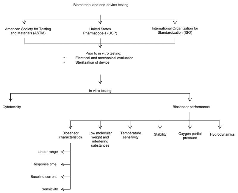
Hierarchal organization of in vitro sensor testing
Sensors often fail from mechanical or electrical malfunctions, such as lead wire breakage, battery discharge, component failure of telemetry packs [53, 54] or package failures [40]. Ensuring mechanical and electrical stability of the sensor in a corrosive environment, such as the mammalian body, is critical before proceeding to in vitro and then in vivo biocompatibility testing (Figure 2). A simple test to assess the ruggedness of the sensor is submerging the active sensor in Ringer’s solution at 37C and making measurements for approximately 4 weeks [39]. Stability of the reference electrode (Ag/AgCl) should also be examined, not only to ensure that reference potential variations do not occur [55], but also to assess the possibility of electrode breakdown and subsequent leaching of toxins over time [47].
Sterilization of the sensor prior to in vitro and in vivo biocompatibility testing should be preformed as recommended by the ISO, ASTM and USP. When selecting a sterilization method, two aspects must be considered. The final device must satisfy the Pharmacopoeias’ sterility assurance level (SAL) of 10−6, in which the probability of a not more than one ppm microorganisms exist in the sterilized final product. Secondly, the functionality of the sensor must not be compromised by sterilization [56].
Gamma irradiation, alkalinized glutaraldehyde solutions of 2–3% and combination sterilization treatments, including universal homogeneous ultraviolet irradiation with hydrogen peroxide inclusion compounds, all alter in vitro biosensor performance to varying degrees, and do not guarantee to meet the sterility assurance level [56].
The ISO 10993-7 [57] provides standards specific for ethylene oxide (EtO) sterilization, a method of gas sterilization commonly used in the medical industry. Gas sterilization is recommended for devices that can not withstand high temperatures [58]; however, this approach comes with the risk of toxic and carcinogenic residues remaining on the device [56, 59]. Cytotoxicity testing of EtO sterilized sensors verify that sensors degassed for the recommended period of time will not contaminate cells with ethylene oxide residues [47], though the desired level of sterility can not always be guaranteed from EtO sterilization [42]. The effects of EtO sterilization on sensor function vary widely, with some groups observing minimal or no alternations to sensor sensitivity [47, 55, 60], while other groups caution against using gaseous sterilization [59] and report total loss of sensor function post EtO sterilization [61].
Occasionally, proper sterilization, in accordance with these standards, is not always performed. In at least one published case, implanted sensors were not sterilized at all, reasoning that clean room construction was sufficient [41]. Another instance argued that the chemical sterilization methods of that time had adverse effects on the sensor [62]. Consequently, whether sensors would remain functional after recommended sterilization techniques is not known for many of the biosensors described in the literature [27]. Moreover, efforts to minimize microbial contamination throughout the manufacturing process lessens but does not obviate product sterilization [56].
4. In vitro biocompatibility testing
Currently, no single in vitro test or finite series of in vitro tests appear to be capable of accurately predicting in vivo sensor performance. For example, consider Table 2 which compares the sensitivity, background current and response times for glucose sensors tested in vitro and in vivo. These results represent only a fraction of the literature showing substantial variability. The problem is further confounded by the diversity of in vitro testing protocols employed by different research groups. For the purposes of this review, we have separated in vitro testing into two groups: cytotoxicity testing and in vitro sensor performance testing.
Table 2.
Comparison of in vitro and in vivo performance of glucose oxidase based glucose sensors using different test species and different in vivo testing periods.
| Species | Implantation Site | Sensitivity (nA/mmol per litre) | Background Current (nA) | Response Time | |||
|---|---|---|---|---|---|---|---|
| In Vitro | In Vivo | In Vitro | In Vivo | In Vitro | In Vivo | ||
| Rats after 3 days[66] | Interscapular subcutaneous tissue | 1.7 ± 0.2 | 0.5 ± 0.1 | 1.9 ± 0.4 | 5.8 ± 1.4 | 190 ± 0.4 s (T90%)* | < 300 s |
| Dogs after 36 hours [41] | Neck subcutaneous tissue | 1.7 ± 0.7 | 1.6 ± 0.8 | 1.4 ± 0.4 | 1.3 ± 0.5 | < 300 s (T95%)† | Not provided |
| Humans after 7 hours [43] | Abdominal subcutaneous tissue | 0.7 ± 0.3 | 0.2 ± 0.1 | 0.3 ± 0.1 | 1.1 ± 0.1 | 24 s (T90%)* | Not provided |
| Dogs after 10 days [74] | Interscapular subcutaneous tissue | ~ 6 | ~ 3 | Not provided | Not provided | Not provided | Not Provided |
| Humans after 2 hours [44] | Abdominal subcutaneous tissue | 0.4 ±0.1 | 0.1 ± 0.02 | 0.4 ± 0.2 | 0.9 ± 0.3 | 290 ± 110 s | 580 ± 290 s |
T90% refers to the time required to reach 90% of the in vitro steady-state response after a step change in bulk glucose concentration
T95% refers to the time required to reach 95% of the in vitro steady-state response after a step change in bulk glucose concentration
4.1 Cytotoxicity testing
Despite constructing a biosensor from biocompatible materials, the intact biosensor assembly itself may or may not be biocompatible. Therefore, separate biocompatible testing of the intact sensor configuration should be performed. As outlined in Table 1, cytotoxicity testing of implantable devices is recommended by all regulatory bodies [48–50] and is considered as one of the most fundamental tests for biocompatibility [47]. In fact, tissue culture methods are frequently more sensitive than animal models to toxins [63]. Within the cytotoxicity standards, a variety of test choices, such as direct or indirect contact tests [7], are available for the investigator to select the most applicable toxicity test for the device. Modifications to the recommended tests have also been made to increase the sensitivity of the tests to toxins [47, 60].
Examination of mouse fibroblast cells (L-929) after being exposed to biomaterials for several days is commonly used to test for leachable toxic substances in the material and for residual solvents used during material preparation [64, 65]. One method for evaluating toxicity levels involved using the ASTM zone index [47]. The zone index assigns grades (0 to 5) based on the size of the dead cell region around the test specimen. Any specimens greater than 0 demonstrate toxicity [50]. Another method involved microphotographing the cell cultures and measuring changes in spatial distributions and morphological changes [47]. Rating scales with corresponding descriptions for morphological changes such as those outlined in ISO 10993-5 Biological Evaluation of Medical Devices Part 5: Tests for in vitro cytotoxicity [7] and the United States Pharmacopeia Section 87 Biological Reactivity Tests In Vitro [48], can also be consulted when determining whether cellular changes are significant enough to consider the test specimen toxic.
4.2 In vitro sensor performance testing
There are several key areas that should be addressed when characterizing sensor performance: linear range, response time, baseline current and sensor sensitivity. The response of glucose sensors should be linear from 0 mM to a minimum of 22.2 mM (400 mg/dL) of glucose [66]. To account for both physiological (normoglycemia) and pathophysiological (hypo- and hyperglycemia) ranges, sensors should measure between 1 mM and 30 mM (20 to 600 mg/dL) [9]. Emphasis should be placed on reliably detecting glucose concentrations below the normoglycemic, as hypoglycaemia can occur rapidly, with acute and potentially fatal complications.
In vitro response time (T90 - T95%) of the sensor should be as rapid as possible since implantation reduces sensor response time (see Table 2). In vivo response times (T90%) greater than seven minutes may present problems in monitoring patients [40], when blood glucose levels fluctuate rapidly, such as with brittle diabetes. Ideally, response time should be less than 5 minutes [9, 67].
A more relevant description of sensor dynamics may be gleaned from the maximum change in glucose concentration a sensor can accurately track in vitro [53]. Though analyzing sensor response to step changes is easier than ramp changes, sensor performance also should be evaluated using ramp changes in glucose, as gradual perturbations in substrate concentration create test conditions more representative of actual in vivo test [68].
4.2.1 Low molecular weight and interfering substances
Low molecular weight substances and electrochemically active molecules affect in vitro sensor sensitivity and baseline current. High sensitivity to glucose in vitro is reported to increase electrode fouling in vivo since the sensor membrane allows easy diffusion of low molecular weight substances into the sensor [43]. In vitro sensitivities less than 1 nA/mmol per litre have been found to have increased sensor failure in vivo. In vivo dog experiments by Pickup et al [44], further confirm this finding, in which a 369 ±127 pA/mmol per litre in vitro sensitivity produced a 52.1 ± 21.5 pA/mmol per litre in vivo sensitivity to glucose.
Evaluating membrane permeability to low molecular weight substances may provide an effective way in determining the susceptibility of sensor fouling in vivo. Though phosphate buffer saline (PBS) at pH 7.4 appears to be the standard test solution for evaluating sensor performance, more aggressive solutions to PBS are undiluted, heparinized plasma [43, 69] and serum [42, 55, 70]. These media provide conditions in which the sensor’s performance to low molecular weight substrates can be assessed. While some of the literature reports no apparent differences in glucose sensitivity between buffer and plasma [69], others report significant decreases in sensitivity and increases in baseline current when testing sensor response in plasma or serum [43, 55]. Once sensors are removed from the serum or plasma and retested in buffered saline, the sensitivity is often restored [47, 70]. Kerner et al [43] hypothesize substances less than 10 kDa contribute to sensor inactivation as these molecules diffuse through the membrane and impair sensor activity through various mechanisms, including electrode fouling and inhibition of enzymes. Gerritsen et al [70] contributes inhibition of glucose oxidase activity to oxidants present in the serum with molecular weights less than 1 kDa. These oxidants, many of which are unknown compounds, compete with oxygen molecules for the electrons generated from glucose oxidase oxidization, resulting in decreased hydrogen peroxide formation and thus a reduction in sensor current [70]. Low molecular weight compounds approximately 200 Da in size have also been reported to foul electrodes [71, 72].
Electrochemically active physiological compounds, either naturally occurring compounds in the body or exogenous therapeutic agents [8], interfere with the sensor current. Table 3 outlines predominate interfering molecules present in vivo. In vitro testing should include assessing sensor response to various interfering molecules at physiological serum concentrations as some interferents greatly affect the output current of the sensor [55], namely urate [73] and acetaminophen [54, 55, 74, 75]. Commonly prescribed diabetic medication and antioxidants are other compounds that the sensor should be tested against. Based on the in vitro performance of the sensor in the presence of these interferents, the membrane can be optimized to enhance sensor selectivity against these molecules, and thus, improve sensor performance in vivo. The reader is encouraged to review Wilson et al [76] which further emphasizes biosensor performance criteria, including interferences, selectivity and sensitivity. To crudely reflect the in vivo immune response, fresh, heparinized whole blood should also be used to investigate interferents. Blood contains several of the low molecular weight molecules mentioned previously, as well as cells and cell secretions that can inactivate the sensor. In vivo, proteolytic enzymes, secreted by polymorphonuclear granulocytes, adsorb to the sensor surface, hindering glucose diffusion to the sensor [70]. Proteolytic enzymes and powerful oxidizing agents can also severely degrade the sensor membrane [77]. Membrane cracking may cause rapid sensor failure [40] as catalase, peroxidase, and even cells [45] migrate into the interior of the sensor, leading to electrode malfunctions. Moreover, activated immune cells consume high levels of glucose and oxygen, decreasing the amount of glucose and oxygen available for diffusion into the sensor. Substances secreted by granulocytes consume hydrogen peroxide, reducing the sensor reaction rate [70]. Though the in vitro use of blood will not mimic the in vivo immune response precisely, a more representative analysis of how the sensor will perform in the human body can be made than by simply using PBS.
Table 3.
Various interferents present in the in vivo environment *
| Interferent | Concentration (mM) in serum |
|---|---|
| ascorbic acid | 0.01 – 0.11 |
| acetaminophen | <0.17 |
| fructose | <0.4 |
| L-cysteine | 0.03–0.10 |
| potassium chloride | 10 |
| sodium chloride | 200 |
| urate | 0.4 |
| urea | 1.3 – 4.3 |
4.2.2 Temperature
Changes in temperature have a profound effect on sensor output current, both in vitro [55, 73] and in vivo [78]. Kerner et al [43] report that decreases in in vivo sensitivity can be partially attributed to calibrating the sensor at room temperature (~20–24 C) in vitro. Experiments investigating the effects of temperature on in vivo oxygen sensors reported that a 1C change in vitro altered sensor output current by 1–2%, while a 1C change in vivo produced a 13.8 ± 5.9% change in oxygen sensor output in vivo, presumably due to increases in microvascular perfusion near the sensor [78]. Undoubtedly, the impact of temperature on sensor output current warrants thorough investigation. Sensors implanted subcutaneously would experience some degree of daily temperature fluctuation. Introducing a gradual change in temperature during in vitro testing would be advantageous to account for both internal and external thermal changes, such as the inflammatory response, fevers, exercise and sunlight.
4.2.3 Stability
Sensor stability testing has been poorly documented in the literature. Assessing the reference electrode stability as well as the operational and storage stability of the sensors in vitro are additional tests recommended to assure the sensor will perform optimally in vivo. Bindra et al [55] and Schmidtke et al [73] both outline methodologies to evaluate sensor stability. Briefly, sensors should be stored in PBS with a glucose concentration of 5.5 mM (100 mg/dL) for 7 days. Each day, sensors should be calibrated to examine changes in membrane permeability through glucose sensitivity, linearity and glucose detection limits [55].
4.2.4 Oxygen partial pressure
Since glucose oxidase based amperometic glucose sensors produce current as hydrogen peroxide oxidizes or as oxygen reduces [79], oxygen availability can be a limiting factor in sensor response. It is well reported that fluctuations in oxygen concentration impact glucose oxidase based sensor performance [53, 68, 78, 80], both in vitro and in vivo. The subcutaneous oxygen tension for humans under normal perfusion is approximately 55 to 70 mmHg (~7kPa – 9kPa) [44, 81], but can range in extenuating circumstance from less than 40 mmHg (~5kPa) to 130 mmHg (~17 kPa) [81]. Factors affecting tissue partial pressure include anaesthetics [82] and hypoxia at the implantation site [81, 83].
Experiments in which sensors were tested over a partial pressure range of 7.5 mmHg to 150 mmHg (1kPa to 21 kPa) show that the linear response range of a sensor will affect the sensor’s dependence on oxygen tension: non-linear sensors are more strongly affected by decreases in oxygen tension, resulting in decreases in sensitivity [55]. Testing the sensor at different oxygen partial pressures to ensure the sensor response is linear over the hypo- and euglycemic ranges in vitro is recommended before conducting in vivo investigations.
4.2.5 Hydrodynamics
The effects of stirring the test medium during in vitro calibration procedures have been investigated by several authors. Both Kerner et [43] and Bindra et al [55] found that non-stirred conditions had no effect on the sensor response in vitro. This indicates that the sensors will not be affected by minor glucose deletion regions that may form around the sensor once implanted. Nevertheless, Ertefai et al [78] contribute calibrating the sensor in vitro in stirred conditions produce artefacts in sensor response in vivo. The effects of stirring on in vivo sensor responses were not reported by Kerner [43] or Bindra [55]. Further investigation as to whether stirring results in in vivo artefacts should be conducted.
5. In vivo biocompatibility testing
Several systems have been developed to assist in evaluating sensor biocompatibility and foreign body response in vivo (Figure 3). As with in vitro testing, great variance exists among in vivo testing protocols, including placement of the sensor within the body, dosage, route of glucose administration, and duration of studies. To further confound in vivo testing, the accuracy of animal models predicting sensor response in humans is also questionable.
Figure 3.
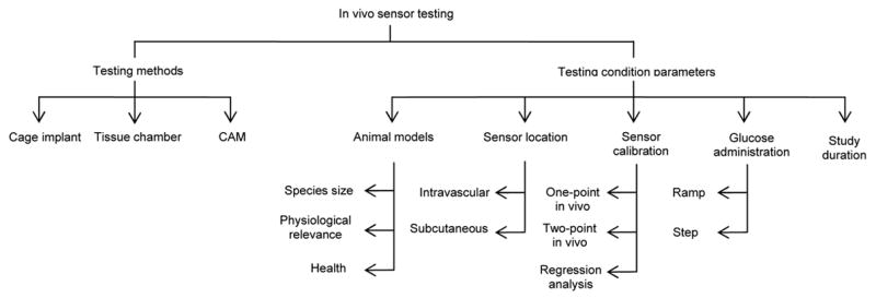
Basic organization of in vivo sensor testing
5.1 Cage implant system
The in vivo stainless steel cage implant system provides an excellent way to assess the inflammatory response to a biomaterial [84–88] or sensor [27, 42]. The cage implant method allows for serial examination of the fluid surrounding the sensor, without needing to sacrifice the animal until of end of the experiment [85]. Briefly, the specimen of interest, either biomaterial or sensor, is inserted into a stainless steel mesh cage (see Figure 4), which is then implanted into a test subject. Using a syringe, exudate from within the cage can be collected over the course of the experiment to examine for inflammatory cells, enzyme secretions, cell-material interactions including fibrous encapsulation and the presence of infection [42, 86]. The effectiveness of glucose diffusion to the sensor can also be gleaned [70]. Examining the exudate for antibodies against biosensor material components is recommended as the immune response against the sensor contributes to loss in sensor sensitivity [64]. Detection of antibodies specific for the biomaterials used in the biosensor construct could indicate the development of latent complications or bioincompatibility in the host, which may result in eventual sensor failure [65]. Additionally, the biocompatibility of the specimen can be directly related to the leukocyte concentration of the exudate. Leukocyte concentrations greater than those found in the control cage exudate indicate an inflammatory response and suggest specimen bioincompatibility [42]. One potential problem with this method is that the host response to the cage may dwarf the body’s response to the sensor.
Figure 4.
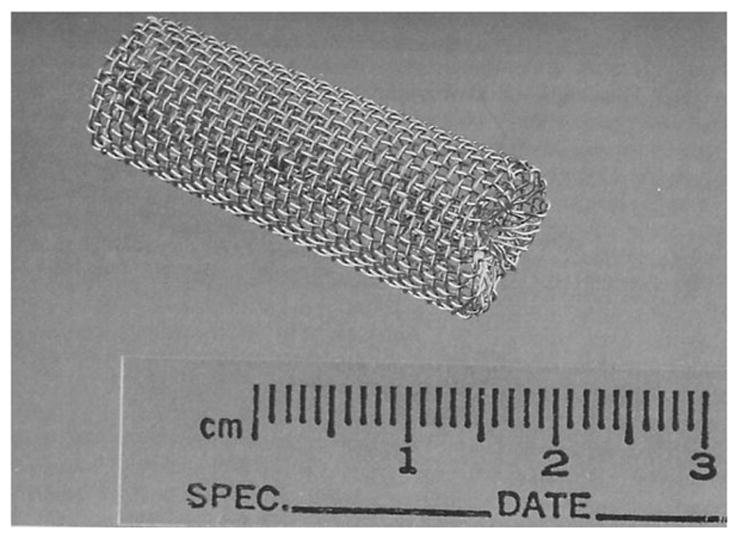
Implantable stainless steel cage. Reprinted from Kao WJ and JM Anderson, “Chapter 42: The Cage Implant Testing System”, in Handbook of Biomaterials Evaluation: Scientific, Technical, and Clinical Testing of Implant Materials, ed. AF von Recum, 659–669, with permission from CRC Press, LLC.
5.2 Tissue chamber system
Another option for in vivo testing utilizes tissue chambers, in which a light weight aluminium or titanium frame is fastened chronically to the dorsum of a test animal, such as a rat or hamster (see Figure 5) [78, 89, 90]. A skin fold is secured between the two plates using stainless steel bolts and a sensor is inserted into the skin fold. Ertefai et al [78] inserted a temperature probe, oxygen sensor and glucose sensor into the skin flap to monitor the effects of temperature and oxygen partial pressure on the glucose sensor output. This arrangement lends itself to convenient histological evaluation of the sensor. Real-time visualization of a glucose sensor could be possible by removing skin from the dorsal flap and securing the fascia layers between the glass windows constructed in the plates, similar to the technique used to visualize tumour growth and microvascularization in rats [89]. In addition to non-destructively visualizing cells, tissue, and microvascular structures and their function over time, inhibitory effects on sensor performance or microcirculatory function caused by anaesthesia is avoided [90] as this system does not require the animal to be sedated during the course of the experiment. However, by removing the skin flap, the host’s biological response to glass may be observed instead of the foreign body response to the sensor. Furthermore, the skin in the tissue chamber will not be at body temperature, but instead be at ambient temperature, due to the cooling effect the chamber construct creates.
Figure 5.
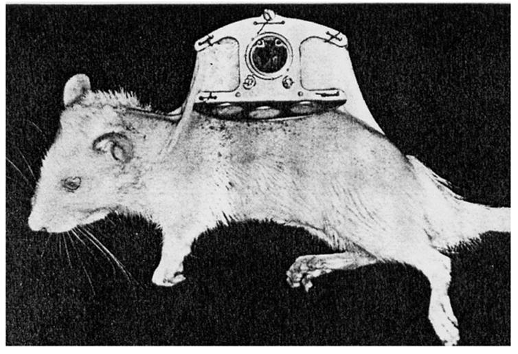
The tissue chamber system with removable window on a female rat. Reprinted from Microvascular Research, 18(3), Papenfuss HD, Gross JF, Intaglietta M, Treese FA, Transparent Access Chamber from the Rat Dorsal Skin Fold, 311–318, 1979, with permission from Elsevier.
5.3 Avian chorioallantoic membranes
Recently, Valdes et al. [91, 92] proposed an alternative to tissue viewing chambers, as well as an innovative alternative to mammalian models for testing biomaterials and biosensors. Using the avian chorioallantoic membrane (CAM) of a developing chicken embryo provides an economical and simple model in which tissue response can be observed undisruptive through this extra-embryonic membrane. Testing of CAM confirmed that acute and chronic inflammatory responses elicited with CAM model were similar to those produced in mammalian models. Sensors are coated with either ovalbumin or egg white and then placed on top of the CAM. After approximately 1 week, the CAM fully incorporates the sensors into its tissue (see Figure 6). Test solutions are injected into the CAM through a vein, after which the response of the sensors to the test solution is monitored. Due to the translucent nature of the tissue, continuous visualization of the sensor is possible through the membrane, without disturbing the model or sensor. How accurately the data generated from this model can predict sensor biocompatibility in humans remains uncertain.
Figure 6.
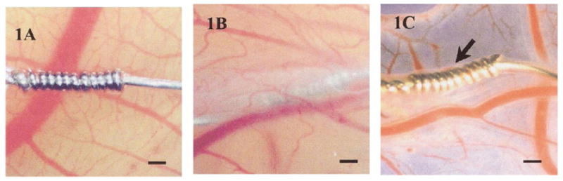
(1A) Acetaminophen sensor not coated with protein. Without a protein coating, the sensor fails to become incorporated into the ex ova CAM tissue after 1 week. (1B) After sensor is coated with protein (ovalbumin or egg white), sensor is fully incorporated into the CAM tissue after 1 week. (1C) Image of sensor after being explanted from CAM after 1 week. Size bar = 250 μm. Reprinted from the Journal of Biomedical Materials Research, 67 A(1), Valdes TI, Klueh U, Kreutzer D, Moussy F, Ex ova chick chorioallantoic membrane as a novel in vivo model for testing biosensors, 215-23, 2003, with permission from John Wiley & Sons, Inc.
5.4 Animal models
Animal models are used to test the safety, efficacy and biocompatibility of implanted devices within the body [93]. Over the decades, in vivo evaluation of biosensors have been conducted on a wide variety of animals, including mice [45], rats [78], dogs [40, 44, 53], chimpanzees [79], as well as in humans [43, 44, 94]. The parameters that should be considered when selecting an animal model include, but are not limited to, animal size, health, ability to stimulate conditions homologous or analogous to that of humans [95], cost, complexity of handling and availability.
5.4.1 Animal size
Blood collection during in vivo studies is necessary to assess how accurately the sensor response correlates with blood glucose levels. Daily blood samples should not exceed 0.05% of the animal’s body weight and no more than 0.5% of the animal’s body weight in blood should be taken within a two week time span [96]. Using small animals, such as rats, limits the amount of blood that can be safely sampled, thus, limiting the extent of testing that can be performed [78]. Using larger animals, such as dogs or pigs, would be more advantageous than smaller animals if serial blood samples were required daily.
5.4.2 Reliability of animal models
How physiologically relevant are animal models for predicting the human in vivo environment? Wisniewski et al [77] cautioned researchers when extrapolating data obtained from rat biocompatibility studies to humans, as significant physiological differences were noticed at the material-tissue interfaces of these two species during microdialysis experiments. Glucose diffusion in rats does not mimic that of humans, primarily due to differences in interstitial space [77, 97]. Humans also have considerably more subcutaneous fat than rats. The more fat cells present, the more tortuous the path is for glucose in adipose tissue. Therefore, glucose diffusion coefficient from humans through adipose tissue is hypothesized to be less than that for rats [77].
Unlike rats, which suffer from decreases in glucose concentration in the days following microdialysis probe implantation, human glucose levels have been found to increase and eventually stabilize after 3 days post implantation [77]. This suggests that humans are not affected to the same extent as rats by physical and vascular factors, such as encapsulation, biofouling and wound healing phenomena [77]. The type of tissue the probes were implanted in during this experiment may have also contributed to these results. Implanting the probes into more fatty regions of the rat may have yielded different results. Researchers should not become discouraged if sensor performance is not successful in rat models, as these animals do not accurately reflect the human in vivo environment.
5.4.3 Health of test subject
Human test subjects used to evaluate in vivo biosensor performance are often not reflective of the diabetic population that will use these sensors. The test population is skewed, as subjects employed are commonly young, healthy and physically fit individuals, based on the reported average body mass index of the subjects [44, 77, 94]. Unlike healthy individuals, diabetics experience changes in microvascular structures over time, which can alter peripheral cutaneous blood fluid [98] and inevitably affect blood supply to subcutaneously implanted sensors.
Animals with diabetes-related cardiovascular complications might appear as suitable models for sensor testing; however, the disadvantages associated with using diabetic animals often outweigh the advantages. Though the in vivo environment of a diabetic animal may be more similar to that of a diabetic human than a non-diabetic animal, diabetic animals are very expensive to purchase and maintain. The blood glucose of the animal must be monitored and insulin injections must be administered similar to that of a human diabetic. The progression of diabetic complications within animals of the same species is highly variable, greatly increasing the difficulty of evaluating experimental results. Though selecting diabetic animals as test models may not be optimal, selecting animals that have high deposits of adipose tissue would be recommended to more accurately reflect the interstitial space of humans in which the sensor will eventually be placed. If results of in vivo testing are successful, proceeding to human models should be considered. The risks involved with inserting a subcutaneous sensor into a human is minimal and the information gleaned from retesting in diabetic models often does not support sacrificing additional animals.
Nevertheless, if in vivo testing using a diabetic model is preferred, dogs are often a suitable choice. Dogs are easily rendered diabetic [95]; however, they fail to develop extensive atherosclerosis or cardiovascular disease [99, 100]. Ossabaw pigs may become the model of choice for studying diabetes, as these animals, when placed on a high fat, low exercise diet for several months develop precursors of diabetes and heart disease, including hardening of the arteries, elevated blood sugar and fat levels and increased blood pressure [101]. For intravascular implanted sensors, pigs and non-human primates would be the most optimal test animal to study thrombogenicity, while dogs, followed by non-human primates, provide the most suitable model for hemodynamics investigations [95].
5.5 Optimal sensor location in body
Though other locations within the body have been considered for glucose detection sites, subcutaneous versus intravascular sensor implantation is primarily debated. Intravascular placement allows for direct measurement of blood glucose concentrations [53, 78], as placement in a blood vessel negates issues surrounding glucose transfer through tissues. However, hemocompatibility issues [41], thromboembolic complications and spread of infection [44, 67] limit the clinical applicability of intravascular placement for long-term use [54]. The invasive, complicated implantation procedure also limits the appeal of this location.
Subcutaneous placement relies on well-vascularized, permeable tissue growing around the sensors. Any disruptions of the vasculature, such as vasodilation or vasoconstriction caused by thermal changes or hydrostatic pressure changes will affect glucose supply to the sensor [78]. Interstitial glucose concentrations are equivalent to circulating glucose concentrations only when blood glucose levels are at or near steady state [102]. However, only 5 minutes is required for changes in blood glucose concentration to be reflected in the subcutaneous tissue [67] and there exists less chance of life-threatening responses, such as thrombosis [78] with subcutaneous implanted sensors.
5.6 Sensor calibration
Sensor calibration must be performed before in vivo sensor analysis can be accurately investigated. The literature reports numerous ways to calibrate sensors in vivo, including single point calibration or one-point in vivo calibration [40, 73, 102], two-point in vivo calibration [66, 103] and regression analysis [41]. Calibration ensures that the apparent subcutaneous glucose concentrations accurately reflect the concentrations in the circulating blood. Given the in vitro and in vivo sensor characteristics typically do not correlate (see Table 2), using in vitro data to calibrate an implanted sensor results in inaccurate subcutaneous glucose concentrations [103]. Likewise, one-point in vivo calibration also assumes identical in vivo and in vitro baseline currents, which is often false (see Table 2).
Two point calibration is not based on in vitro data. Instead, this method relies on in vivo sensor output obtained during steady state conditions at two different glucose concentrations [41]. This method has proven successful in both the hyperglycaemic and hypoglycaemic ranges and is reportedly the most reliable method [103]. Another calibration method not based on in vitro sensor characteristics is regression analysis. The advantage of this method is that artificially induced glycemic fluctuations are not required to calibrate the sensor in vivo, unlike the two point calibration method [41], making regression analysis more feasible in terms of daily clinical practice [104]. In human models, slight fluctuations in intracutaneous glucose concentrations will occur during the course of the day, allowing for easy calibration of the sensor, without having to intentionally induced changes in glucose concentrations to calibrate the sensor. Nevertheless, it still remains uncertain which calibration method has the most clinical practicality [104].
5.7 Glucose administration
To test the in vivo sensor performance, a high glucose (dextrose) solution is often administered to the animal. Methods of administration include a bolus injection or continuous infusion of glucose, through a venous catheter or directly into the intra-peritoneal cavity [53, 105, 106]. Basal blood glucose levels are typically recorded prior to glucose administration. Following glucose infusion, sensor output is monitored and compared with circulating blood glucose concentrations. Frequently, the in vivo response time of the sensor to a bolus injection is much longer than the in vitro measurements.
Studies in dogs by Armour et al [53] demonstrate that sensor response time and glucose tracking is much more rapid and accurate when glucose is administered gradually, as opposed to injecting a single bolus of glucose (see Figure 7). Similar findings were reported in the literature [40, 44]. Though the bolus glucose infusion protocol tests sensor response in extreme situations [54], gradual glucose infusions (ramp) or oral administration of glucose provides a more physiologically relevant response in animals and is more practical for clinical applications [54].
Figure 7.
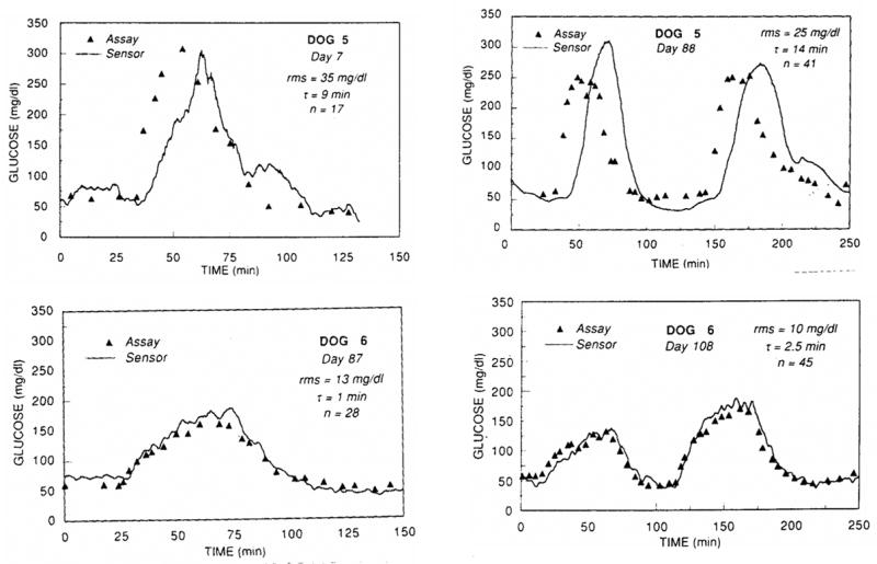
Lower infusion volumes and infusion rates (ramp) allow the implanted sensor in Dog 6 to track glucose more efficiently than Dog 5, who received high infusion volumes and infusion rates of glucose (step). Reprinted from Diabetes, 39(12), Armour JC, Lucisano JY, Mckean BD, Gough DA, Application of Chronic Intravascular Blood-Glucose Sensor in Dogs, 1519–1526, 1990, with permission from the American Diabetes Association.
5.8 Duration of in vivo testing
Experiments that last only a few hours or days do not provide the body sufficient time to respond to the implanted sensor. The first few days up to 2 weeks after implantation are the least favourable time to monitor glucose sensor performance, as fibrous encapsulation of the sensor has not established sufficiently [54], producing sensor output signals similar to in vitro signals at 0mM glucose [40]. Not surprisingly, many in vivo experiments are terminated shortly after commencing the study, since the sensors appear to be malfunctioning.
However, experiments in which in vivo experiments are conducted for weeks and months demonstrate that as the days progress, the sensor signals increase and eventually stabilize [40, 54]. After approximately 10 days following implantation, improvements in sensor response have been reported [74], as resorption of blood clots and tissue repair surrounding the sensor allow for better glucose transport to the sensor. Updike et al [54] coined the “break-in” period as the time during which the fibrous encapsulation becomes vascularized, as the capillary networks surrounding the implant grow towards the capsule as well as form around the tip of the sensor. The break in period begins at the time of implantation and lasts for approximately 4 to 18 days. Once the foreign body capsule has been established, it is possible to monitor glucose from within the capsule over the course of months [54]. Even when sensors fail in vivo, they should not be removed until several weeks or months later, provided that the health of the test subject is not compromised, in order to evaluate the structural stability of the device in a corrosive environment and the host’s foreign body reaction [53].
6. Post explantation
Upon explantation of the sensor, the base current, sensitivity and response time of the sensor in PBS should be evaluated to determine the sensor’s ability to withstand the in vivo environment, as well as to investigate if sensor response can be restored upon explantation. Frequently, sensor sensitivity is restored to the original sensor performance before implantation once the fibrous capsule is removed and the sensor is recalibrated in PBS [40–46]. Scanning the surface of the sensor with an electron microscope to observe for membrane cracks, electrode erosion and cellular adhesion is recommended to better understand how the sensor withstood the in vivo environment.
Histological examination of the tissue surrounding the sensor is also recommended, provided that the sensor did not undergo recalibration in PBS, as such testing will disrupt the fibrous capsule that formed around the sensor [42]. Examination of the fibrous capsule should include observing for capillary growth into the capsule, as well as formation of small vessels at the sensor tip [54, 66, 78, 94]. If sensor placement was intravascular, lung examinations of test animals should be performed to investigate signs of embolic infraction [53]. Various methods for collecting and preserving tissue samples for histological studies are utilized [42, 44, 78]. The ISO and ASTM standards, such as the ASTM standard F 763 [107], should be consulted as these documents outline implant retrieval procedures and provide reliable protocols for performing post implanation investigations.
7. Conclusions
Many of the same issues addressed in Reach and Wilson’s review article [67] over a decade ago remain obstacles today, including the best method for calibrating sensors in vivo, the effects of oxygen tension on sensor response, the most optimal sterilization method and toxicity testing, as well as the impact of interfering molecules on sensor activity. Though some advances have been made in sensor development, such as Abbott Laboratories’ TheraSense FreeStyle Navigator™ Continuous Glucose Sensor and Medtronic’s MiniMed Paradigm® REAL-Time system, much more research and testing is needed before a non-invasive sensor for long-term use can become a reality.
The discussion of in vitro and in vivo testing methods is intended to provide insight into the merits and downfalls of current testing procedures, as well as offering suggested recommendations to improve testing procedures. Prior to commencing biocompatibility testing, the biosensor must (i) be tested for mechanical and electrical stability in corrosive environments, (ii) be sterilized according to published standards as well as, (iii) be tested for post-sterilization performance. Next, in vitro testing of the sensor should consist of both cytotoxicity testing and sensor performance evaluation. Sensor response time and accuracy with which a sensor can track gradual changes in glucose should be investigated. In vitro characterization should include testing the effects of low molecular weight and therapeutic electrochemically active molecules, temperature and oxygen partial pressures on sensor performance.
In vivo testing should be performed first in rodents, as these models are inexpensive, easy to handle, and readily rendered diabetic. Animals more homologous to humans should be used, such as dogs and pigs, to refine the model before beginning human studies. Oral administration of glucose to test animals, rather than infusing the animal with a glucose bolus, may produce more physiologically relevant responses for the sensor to track. The duration of in vivo studies must extend past the “break in” period as testing before this time does not allow the sensor to fully stabilize within the body. Some sensors, even if they have failed, should remain in the animal for several weeks or months in order to evaluate the host foreign body response and structural stability of the device in a corrosive environment. Post implantation testing of sensor performance should be investigated, in addition to histological evaluation of the capsule and adjacent tissue surrounding the implant. By incorporating testing strategies similar to that of Bindra et al [55] and Feldman et al [17], as well as utilizing many of the recommendations suggested throughout this paper, developing reliable biosensors for long-term human appears more promising.
Figure 8.
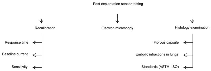
Basic organization of post explantation sensor testing
Acknowledgments
The authors thank Dr Kevin Olbrich, Dr Bruce Klitzman, Dr David Cunningham, Dr Christine Grant, Dr Lori Norton, Andrew MacArthur and John Stroncek for valuable feedback on the manuscript. This work was funded by NIH grant DK54932 (WMR), a Center of Biomolecular and Tissue Engineering Graduate Fellowship (HEK), and the Medtronic Corporation.
Footnotes
Publisher's Disclaimer: This is a PDF file of an unedited manuscript that has been accepted for publication. As a service to our customers we are providing this early version of the manuscript. The manuscript will undergo copyediting, typesetting, and review of the resulting proof before it is published in its final citable form. Please note that during the production process errors may be discovered which could affect the content, and all legal disclaimers that apply to the journal pertain.
Reference List
- 1.National diabetes fact sheet: general information and national estimates on diabetes in the United States. Atlanta, GA: Centers for Disease Control and Prevention, U.S. Department of Health and Human Services; 2005. [Google Scholar]
- 2.Petersen M. Economic costs of diabetes in the US in 2002. Diabetes Care. 2003 Mar;26(3):917–932. doi: 10.2337/diacare.26.3.917. [DOI] [PubMed] [Google Scholar]
- 3.Turner APF, Pickup JC. Diabetes-Mellitus - Biosensors for Research and Management. Biosensors. 1985;1(1):85–115. doi: 10.1016/0265-928x(85)85006-9. [DOI] [PubMed] [Google Scholar]
- 4.Lasker RD. The Diabetes Control and Complications Trial - Implications for Policy and Practice. New England Journal of Medicine. 1993 Sep;329(14):1035–1036. doi: 10.1056/NEJM199309303291410. [DOI] [PubMed] [Google Scholar]
- 5.American diabetes association. Clinical practice recommendations 1997 -Introduction. Diabetes Care. 1997 Jan;20:S1–S1. [PubMed] [Google Scholar]
- 6.Tests of Glycemia in Diabetes. Diabetes Care. 2002;25(90001):97S–99. [Google Scholar]
- 7.Bloomgarden ZT. Treatment issues in type 1 diabetes. Diabetes Care. 2002;25(1):230–236. doi: 10.2337/diacare.25.1.230. [DOI] [PubMed] [Google Scholar]
- 8.Fischer U. Fundamentals of Glucose Sensors. Diabetic Medicine. 1991;8(4):309–321. doi: 10.1111/j.1464-5491.1991.tb01603.x. [DOI] [PubMed] [Google Scholar]
- 9.Wilkins E, Atanasov P. Glucose monitoring: State of the art and future possibilities. Medical Engineering & Physics. 1996;18(4):273–288. doi: 10.1016/1350-4533(95)00046-1. [DOI] [PubMed] [Google Scholar]
- 10.Gabbay R. New Developments in Home Glucose Monitoring: Minimizing the Pain. Can J Diabetes. 2003;27(3):371–376. [Google Scholar]
- 11.Tamada JA, Garg S, Jovanovic L, Pitzer KR, Fermi S, Potts RO. Noninvasive glucose monitoring - Comprehensive clinical results. Jama-Journal of the American Medical Association. 1999;282(19):1839–1844. doi: 10.1001/jama.282.19.1839. [DOI] [PubMed] [Google Scholar]
- 12.Pitzer KR, Desai S, Dunn T, Edelman S, Jayalakshmi Y, Kennedy J, et al. Detection of hypoglycemia with the GlucoWatch biographer. Diabetes Care. 2001;24(5):881–885. doi: 10.2337/diacare.24.5.881. [DOI] [PubMed] [Google Scholar]
- 13.Cygnus Customer Service Representative. Telephone Conversation. 2004.
- 14.Press Release: FDA Clears New Diabetes Device for Marketing. U.S. Department of Health and Human Services. U.S. Food and Drug Administration. 2003.
- 15.Medtronic MiniMed. Medtronic MiniMed, Inc; Northridge, CA: REAL-Time Continuous Glucose Monitoring. [Company Product Information Web Page] 2006 [cited 2006]; Available from: http://www.minimed.com/products/insulinpumps/components/cgm.html. [Google Scholar]
- 16.Medtronic MiniMed Customer Service Representative. Telephone Conversation. Northridge, CA: 2006. [Google Scholar]
- 17.Feldman B, Brazg R, Schwartz W, Weinstein R. A continuous glucose sensor based on wired enzyme technology - results from a 3-day trial in patients with type 1 diabetes. Diabetes Technol Ther. 2003;5:769–779. doi: 10.1089/152091503322526978. [DOI] [PubMed] [Google Scholar]
- 18.Feldman B. The Free-Style Navigator™ Continuous Glucose Monitor: Complete results from a home-use trial. Diabetes Technol Ther. 2004;6(2):218. [Google Scholar]
- 19.Klonoff DC. A review of continous glucose monitoring technology. Diabetes Technol Ther. 2005;7(5):770–775. doi: 10.1089/dia.2005.7.770. [DOI] [PubMed] [Google Scholar]
- 20.Hullegie LM, Lutgers HL, Dullaart RPF, Sluiter WJ, Wientjes KJ, Schoonen AJM, et al. Effects of glucose and insulin levels on adipose tissue glucose measurement by microdialysis probes retained for three weeks in Type 1 diabetic patients. Netherlands Journal of Medicine. 2000;57(1):13–19. doi: 10.1016/s0300-2977(00)00023-1. [DOI] [PubMed] [Google Scholar]
- 21.Lutgers HL, Hullegie LM, Hoogenberg K, Sluiter WJ, Dullaart RPF, Wientjes KJ, et al. Microdialysis measurement of glucose in subcutaneous adipose tissue up to three weeks in Type 1 diabetic patients. Netherlands Journal of Medicine. 2000;57(1):7–12. doi: 10.1016/s0300-2977(00)00022-x. [DOI] [PubMed] [Google Scholar]
- 22.Gebhart S, Faupel M, Fowler R, Kapsner C, Lincoln D, McGee V, et al. Glucose sensing in transdermal body fluid collected under continuous vacuum pressure via micropores in the stratum corneum. Diabetes Technol Ther. 2003;5(2):159–166. doi: 10.1089/152091503321827812. [DOI] [PubMed] [Google Scholar]
- 23.Garg SK, Schwartz S, Edelman SV. Improved glucose excursions using an implantable real-time continuous glucose sensor in adults with type 1 diabetes. Diabetes Care. 2004;27(3):734–738. doi: 10.2337/diacare.27.3.734. [DOI] [PubMed] [Google Scholar]
- 24.GlucoWatch approved for children with diabetes. FDA Consum. 2002;36(6):6–6. [PubMed] [Google Scholar]
- 25.Garg SK, Potts RO, Ackerman NR, Fermi SJ, Tamada JA, Chase HP. Correlation at fingerstick blood glucose measurements with GlucoWatch biographer glucose results in young subjects with type 1 diabetes. Diabetes Care. 1999;22(10):1708–1714. doi: 10.2337/diacare.22.10.1708. [DOI] [PubMed] [Google Scholar]
- 26.Medtronic MiniMed Customer Service Representative. Telephone Conversation. Northridge, CA: 2007. [Google Scholar]
- 27.Reichert WM, Sharkawy AA. Biosensors. In: von Recum AF, editor. Handbook of Biomaterials Evaluation: Scientific, Technical, and Clinical Testing of Implant Materials. Philadelphia: Taylor&Francis; 1999. pp. 439–459. [Google Scholar]
- 28.Gerritsen M. Problems associated with subcutaneously implanted glucose sensors. Diabetes Care. 2000;23(2):143–145. doi: 10.2337/diacare.23.2.143. [DOI] [PubMed] [Google Scholar]
- 29.Reichert WM, Saavedra SS. Materials considerations in the selection, performance and adhesion of polymeric encapsulants for implantable sensors. In: Williams DF, editor. Science and Technology - A Comprehensive Treatment. 1992. pp. 303–343. [Google Scholar]
- 30.Wisniewski N, Moussy F, Reichert WM. Characterization of implantable biosensor membrane biofouling. Fresenius Journal of Analytical Chemistry. 2000;366(6–7):611–621. doi: 10.1007/s002160051556. [DOI] [PubMed] [Google Scholar]
- 31.Wisniewski N, Reichert M. Methods for reducing biosensor membrane biofouling. Colloids and Surfaces B-Biointerfaces. 2000;18(3–4):197–219. doi: 10.1016/s0927-7765(99)00148-4. [DOI] [PubMed] [Google Scholar]
- 32.Updike SJ, Shults MC, Gilligan BJ, Rhodes RK. A subcutaneous glucose sensor with improved longevity, dynamic range, and stability of calibration. Diabetes Care. 2000 Feb;23(2):208–214. doi: 10.2337/diacare.23.2.208. [DOI] [PubMed] [Google Scholar]
- 33.Sharkawy AA, Klitzman B, Truskey GA, Reichert WM. Engineering the tissue which encapsulates subcutaneous implants .1. Diffusion properties. Journal of Biomedical Materials Research. 1997;37(3):401–412. doi: 10.1002/(sici)1097-4636(19971205)37:3<401::aid-jbm11>3.0.co;2-e. [DOI] [PubMed] [Google Scholar]
- 34.Sharkawy AA, Klitzman B, Truskey GA, Reichert WM. Engineering the tissue which encapsulates subcutaneous implants. II. Plasma-tissue exchange properties. Journal of Biomedical Materials Research. 1998;40(4):586–597. doi: 10.1002/(sici)1097-4636(19980615)40:4<586::aid-jbm10>3.0.co;2-e. [DOI] [PubMed] [Google Scholar]
- 35.Sharkawy AA, Klitzman B, Truskey GA, Reichert WM. Engineering the tissue which encapsulates subcutaneous implants. III. Effective tissue response times. Journal of Biomedical Materials Research. 1998;40(4):598–605. doi: 10.1002/(sici)1097-4636(19980615)40:4<598::aid-jbm11>3.0.co;2-c. [DOI] [PubMed] [Google Scholar]
- 36.Sieminski AL, Gooch KJ. Biomaterial-microvasculature interactions. Biomaterials. 2000 Nov;21(22):2233–2241. doi: 10.1016/s0142-9612(00)00149-6. [DOI] [PubMed] [Google Scholar]
- 37.Marshall AJ, Irvin CA, Barker T, Sage EH, Hauch KD, Ratner BD. Biomaterials with tightly controlled pore size that promote vascular in-growth. Abstracts of Papers of the American Chemical Society. 2004 Aug;228:U386–U386. [Google Scholar]
- 38.Norton LW, Tegnell E, Toporek SS, Reichert WM. In vitro characterization of vascular endothelial growth factor and dexamethasone releasing hydrogels for implantable probe coatings. Biomaterials. 2005;26(16):3285–3297. doi: 10.1016/j.biomaterials.2004.07.069. [DOI] [PubMed] [Google Scholar]
- 39.Klueh U, Dorsky DI, Kreutzer DL. Enhancement of implantable glucose sensor function in vivo using gene transfer-induced neovascularization. Biomaterials. 2005;26(10):1155–1163. doi: 10.1016/j.biomaterials.2004.04.017. [DOI] [PubMed] [Google Scholar]
- 40.Gilligan BJ, Shults MC, Rhodes RK, Updike SJ. Evaluation of A Subcutaneous Glucose Sensor Out to 3 Months in A Dog-Model. Diabetes Care. 1994;17(8):882–887. doi: 10.2337/diacare.17.8.882. [DOI] [PubMed] [Google Scholar]
- 41.Von Woedtke T, Rebrin K, Fischer U, Abel P, Wilke W, Vogt L, et al. In situ calibration of implanted electrochemical glucose sensors. Biomedica Biochimica Acta. 1989;48(11–12):943–952. [PubMed] [Google Scholar]
- 42.Voskerician G, Liu CC, Anderson JM. Electrochemical characterization and in vivo biocompatibility of a thick-film printed sensor for continuous in vivo monitoring. Ieee Sensors Journal. 2005 Dec;5(6):1147–1158. [Google Scholar]
- 43.Kerner W, Kiwit M, Linke B, Keck FS, Zier H, Pfeiffer EF. The Function of A Hydrogen Peroxide-Detecting Electroenzymatic Glucose Electrode Is Markedly Impaired in Human Sub-Cutaneous Tissue and Plasma. Biosensors & Bioelectronics. 1993;8(9–10):473–482. doi: 10.1016/0956-5663(93)80032-k. [DOI] [PubMed] [Google Scholar]
- 44.Pickup JC, Claremont DJ, Shaw GW. Responses and Calibration of Amperometric Glucose Sensors Implanted in the Subcutaneous Tissue of Man. Acta Diabetologica. 1993;30(3):143–148. doi: 10.1007/BF00572858. [DOI] [PubMed] [Google Scholar]
- 45.Clark LC, Jr, Spokane RB, Homan MM, Sudan R, Miller M. Long-term stability of electroenzymatic glucose sensors implanted in mice - an update. ASAIO Journal. 1988;34:259–265. [PubMed] [Google Scholar]
- 46.Fischer U, Hidde A, Herrmann S, Vonwoedtke T, Rebrin K, Abel P. Oxygen-Tension at the Subcutaneous Implantation Site of Glucose Sensors. Biomedica Biochimica Acta. 1989;48(11–12):965–971. [PubMed] [Google Scholar]
- 47.Zhang Y, Bindra DS, Barrau MB, Wilson GS. Application of cell culture toxicity test to the development of implantable biosensors. Biosens Bioelectron. 1991;6:653–661. doi: 10.1016/0956-5663(91)87018-7. [DOI] [PubMed] [Google Scholar]
- 48.United States Pharmacopeial Convention. United States Pharmacopeia. Rockville, MD: United States Pharmacopeial Convention; 2002. The Biocompatibility of Materials Used in Drug Containers, Medical Devices, and Implants; pp. 2091–2098. [Google Scholar]
- 49.Biological evaluation of medical devices - Part 1: Guidance on selection of tests. ISO 10993–1:1992(E). International Organization for Standardization. ISO, 1992.
- 50.Standard practice for selecting generic biological test methods for materials and devices Designation F 748-98. American Society for Testing and Materials. ASTM, 2001.
- 51.Leuschner J. Legal requirements for the preclinical toxicological evaluation of biomaterials. Clin Mater. 1992;10 (1–2):51–57. doi: 10.1016/0267-6605(92)90085-8. [DOI] [PubMed] [Google Scholar]
- 52.Upman P. Testing. In: von Recum AF, editor. Handbook of Biomaterials Evaluation: Scientific, Technical, and Clinical Testing of Implant Materials. Philadelphia: Taylor&Francis; 1999. pp. 275–289. [Google Scholar]
- 53.Armour JC, Lucisano JY, McKean BD, Gough DA. Application of Chronic Intravascular Blood-Glucose Sensor in Dogs. Diabetes. 1990;39(12):1519–1526. doi: 10.2337/diab.39.12.1519. [DOI] [PubMed] [Google Scholar]
- 54.Updike SJ, Shults MC, Rhodes RK, Gilligan BJ, Luebow JO, von Heimburg D. Enzymatic Glucose Sensors - Improved Long-Term Performance In Vitro and In Vivo. ASAIO Journal. 1994;40:157–163. [PubMed] [Google Scholar]
- 55.Bindra DS, Zhang YN, Wilson GS, Sternberg R, Thevenot DR, Moatti D, et al. Design and Invitro Studies of A Needle-Type Glucose Sensor for Subcutaneous Monitoring. Analytical Chemistry. 1991;63(17):1692–1696. doi: 10.1021/ac00017a008. [DOI] [PubMed] [Google Scholar]
- 56.von Woedtke T, Julich WD, Hartmann V, Stieber M, Abel PU. Sterilization of enzyme glucose sensors: problems and concepts. Biosensors & Bioelectronics. 2002;17(5):373–382. doi: 10.1016/s0956-5663(01)00310-4. [DOI] [PubMed] [Google Scholar]
- 57.Biological evaluation of medical devices - Part 7: Ethylene oxide sterilization residuals 10993-7. International Organization for Standardization. ISO, 1995.
- 58.United States Pharmacopeial Convention. United States Pharmacopeia. Rockville, MD: United States Pharmacopeial Convention; 2002. Sterilization and sterility assurance of compendial articles; pp. 2250–2255. [Google Scholar]
- 59.Abel PU, von Woedtke T. Biosensors for in vivo glucose measurement: can we cross the experimental stage. Biosensors & Bioelectronics. 2002 Dec;17(11–12):1059–1070. doi: 10.1016/s0956-5663(02)00099-4. [DOI] [PubMed] [Google Scholar]
- 60.Ohashi E, Karube I. Development of A Thin Membrane Glucose Sensor Using Beta-Type Crystalline Chitin for Implantable Biosensor. Journal of Biotechnology. 1995;40(1):13–19. doi: 10.1016/0168-1656(95)00028-o. [DOI] [PubMed] [Google Scholar]
- 61.Vering T, Adam S, Drewer H, Dumschat C, Steinkuhl R, Schulze A, et al. Wearable microdialysis system for continuous in vivo monitoring of glucose. Analyst. 1998 Jul;123(7):1605–1609. doi: 10.1039/a800017d. [DOI] [PubMed] [Google Scholar]
- 62.Rebrin K, Fischer U, Vondorsche HH, Von Woetke T, Abel P, Brunstein E. Subcutaneous Glucose Monitoring by Means of Electrochemical Sensors -Fiction Or Reality. Journal of Biomedical Engineering. 1992;14(1):33–40. doi: 10.1016/0141-5425(92)90033-h. [DOI] [PubMed] [Google Scholar]
- 63.Johnson HJ, Northup SJ, Seagraves PA, Atallah M, Garvin PJ, Lin L, et al. Biocompatibility Test Procedures for Materials Evaluation Invitro .2. Objective Methods of Toxicity Assessment. Journal of Biomedical Materials Research. 1985;19(5):489–508. doi: 10.1002/jbm.820190503. [DOI] [PubMed] [Google Scholar]
- 64.Ziegler M, Schlosser M, Abel P, Ziegler B. Antibody-Response in Rats Against Nontoxic Glucose Sensor Membranes Tested in Cell-Culture. Biomaterials. 1994;15(10):859–864. doi: 10.1016/0142-9612(94)90043-4. [DOI] [PubMed] [Google Scholar]
- 65.Schlosser M, Ziegler M. Biocompatibility of Active Implantable Devices. In: Fraser DM, editor. Biosensors in the Body - Continuous In Vivo Monitoring. Chichester, West Sussex: John Wiley&Sons Ltd; 1997. [Google Scholar]
- 66.Moattisirat D, Capron E, Poitout V, Reach G, Bindra DS, Zhang Y, et al. Towards Continuous Glucose Monitoring - Invivo Evaluation of A Miniaturized Glucose Sensor Implanted for Several Days in Rat Subcutaneous Tissue. Diabetologia. 1992;35(3):224–230. doi: 10.1007/BF00400921. [DOI] [PubMed] [Google Scholar]
- 67.Reach G, Wilson GS. Can Continuous Glucose Monitoring Be Used for the Treatment of Diabetes. Analytical Chemistry. 1992 Mar;64(6):A381–A386. doi: 10.1021/ac00030a001. [DOI] [PubMed] [Google Scholar]
- 68.Lucisano JY, Gough DA. Transient-Response of the Two-Dimensional Glucose Sensor. Analytical Chemistry. 1988;60(13):1272–1281. doi: 10.1021/ac00164a007. [DOI] [PubMed] [Google Scholar]
- 69.Linke B, Kerner W, Kiwit M, Pishko M, Heller A. Amperometric Biosensor for In-Vivo Glucose Sensing Based on Glucose-Oxidase Immobilized in A Redox Hydrogel. Biosensors & Bioelectronics. 1994;9(2):151–158. doi: 10.1016/0956-5663(94)80107-x. [DOI] [PubMed] [Google Scholar]
- 70.Gerritsen M, Jansen JA, Kros A, Vriezema DM, Sommerdijk N, Nolte RJM, et al. Influence of inflammatory cells and serum on the performance of implantable glucose sensors. Journal of Biomedical Materials Research. 2001 Jan;54(1):69–75. doi: 10.1002/1097-4636(200101)54:1<69::aid-jbm8>3.0.co;2-q. [DOI] [PubMed] [Google Scholar]
- 71.Treloar PH, Christie IM, Vadgama PM. Engineering the Right Membranes for Electrodes at the Biological Interface - Solvent-Cast and Electropolymerized. Biosensors & Bioelectronics. 1995;10(1–2):195–201. doi: 10.1016/0956-5663(95)96806-a. [DOI] [PubMed] [Google Scholar]
- 72.Taguchi S, Inaba T, Nishio M, Hata N, Kasahara I, Goto K. Membrane Filters for the Concentration of Trace-Elements in Water - Distribution of Ion-Pairs Between Membrane-Filter and Aqueous Phases. Analyst. 1989;114(4):489–492. doi: 10.1039/an9891400489. [DOI] [PubMed] [Google Scholar]
- 73.Schmidtke DW, Heller A. Accuracy of the one-point in vivo calibration of “wired” glucose oxidase electrodes implanted in jugular veins of rats in periods of rapid rise and decline of the glucose concentration. Analytical Chemistry. 1998;70(10):2149–2155. doi: 10.1021/ac970932u. [DOI] [PubMed] [Google Scholar]
- 74.Moussy F, Jakeway S, Harrison DJ, Rajotte RV. In-Vitro and In-Vivo Performance and Lifetime of Perfluorinated Ionomer-Coated Glucose Sensors After High-Temperature Curing. Analytical Chemistry. 1994;66(22):3882–3888. doi: 10.1021/ac00094a007. [DOI] [PubMed] [Google Scholar]
- 75.Moattisirat D, Velho G, Reach G. Evaluating Invitro and Invivo, the Interference of Ascorbate and Acetaminophen on Glucose Detection by a Needle-Type Glucose Sensor. Biosensors & Bioelectronics. 1992;7(5):345–352. doi: 10.1016/0956-5663(92)85030-e. [DOI] [PubMed] [Google Scholar]
- 76.Wilson GS, Gifford R. Biosensors for real-time in vivo measurements. Biosensors & Bioelectronics. 2005 Jun;20(12):2388–2403. doi: 10.1016/j.bios.2004.12.003. [DOI] [PubMed] [Google Scholar]
- 77.Wisniewski N, Rajamand N, Adamsson U, Lins PE, Reichert WM, Klitzman B, et al. Analyte flux through chronically implanted subcutaneous polyamide membranes differs in humans and rats. American Journal of Physiology-Endocrinology and Metabolism. 2002;282(6):E1316–E1323. doi: 10.1152/ajpendo.00259.2001. [DOI] [PubMed] [Google Scholar]
- 78.Ertefai S, Gough DA. Physiological Preparation for Studying the Response of Subcutaneously Implanted Glucose and Oxygen Sensors. Journal of Biomedical Engineering. 1989;11(5):362–368. doi: 10.1016/0141-5425(89)90097-6. [DOI] [PubMed] [Google Scholar]
- 79.Wagner JG, Schmidtke DW, Quinn CP, Fleming TF, Bernacky B, Heller A. Continuous amperometric monitoring of glucose in a brittle diabetic chimpanzee with a miniature subcutaneous electrode. Proceedings of the National Academy of Sciences of the United States of America. 1998;95(11):6379–6382. doi: 10.1073/pnas.95.11.6379. [DOI] [PMC free article] [PubMed] [Google Scholar]
- 80.Gough DA, Lucisano JY, Tse PHS. Two-Dimensional Enzyme Electrode Sensor for Glucose. Analytical Chemistry. 1985;57(12):2351–2357. doi: 10.1021/ac00289a042. [DOI] [PubMed] [Google Scholar]
- 81.Hopf HW. Development of subcutaneous wound oxygen measurement in humans: Contributions of Thomas K. Hunt, MD. Wound Repair and Regeneration. 2003;11(6):424–430. doi: 10.1046/j.1524-475x.2003.11606.x. [DOI] [PubMed] [Google Scholar]
- 82.Fain JA. Pump up your knowledge of insulin pumps. Nursing. 2003;33(6):51–53. doi: 10.1097/00152193-200306000-00045. [DOI] [PubMed] [Google Scholar]
- 83.Ninikoski J, Heughan C, Hunt TK. Oxygen Tension in Human Wounds. J Surg Res. 1972;12:77–82. doi: 10.1016/0022-4804(72)90124-2. [DOI] [PubMed] [Google Scholar]
- 84.Lindner E, Cosofret VV, Ufer S, Buck RP, Kao WJ, Neuman MR, et al. Ion-Selective Membranes with Low Plasticizer Content - Electroanalytical Characterization and Biocompatibility Studies. Journal of Biomedical Materials Research. 1994;28(5):591–601. doi: 10.1002/jbm.820280509. [DOI] [PubMed] [Google Scholar]
- 85.Marchant R, Hiltner A, Hamlin C, Rabinovitch A, Slobodkin R, Anderson JM. Invivo Biocompatibility Studies .1. the Cage Implant System and A Biodegradable Hydrogel. Journal of Biomedical Materials Research. 1983;17(2):301–325. doi: 10.1002/jbm.820170209. [DOI] [PubMed] [Google Scholar]
- 86.Kao WJ, Anderson JM. The Cage Implant Testing System. In: von Recum AF, editor. Handbook of Biomaterials Evaluation: Scientific, Technical, and Clinical Testing of Implant Materials. Philadelphia: Taylor&Francis; 1999. pp. 659–669. [Google Scholar]
- 87.Kao WYJ, McNally AK, Hiltner A, Anderson JM. Role for Interleukin-4 in Foreign-Body Giant-Cell Formation on A Poly(Etherurethane Urea) In-Vivo. Journal of Biomedical Materials Research. 1995;29(10):1267–1275. doi: 10.1002/jbm.820291014. [DOI] [PubMed] [Google Scholar]
- 88.Zhao Q, Topham N, Anderson JM, Hiltner A, Lodoen G, Payet CR. Foreign-Body Giant-Cells and Polyurethane Biostability - Invivo Correlation of Cell-Adhesion and Surface Cracking. Journal of Biomedical Materials Research. 1991;25(2):177–183. doi: 10.1002/jbm.820250205. [DOI] [PubMed] [Google Scholar]
- 89.Papenfuss HD, Gross JF, Intaglietta M, Treese FA. Transparent Access Chamber for the Rat Dorsal Skin Fold. Microvascular Research. 1979;18(3):311–318. doi: 10.1016/0026-2862(79)90039-6. [DOI] [PubMed] [Google Scholar]
- 90.Makale MT, Lin JT, Calou RE, Tsai AG, Chen PC, Gough DA. Tissue window chamber system for validation of implanted oxygen sensors. 2003. [DOI] [PubMed] [Google Scholar]
- 91.Valdes TI, Kreutzer D, Moussy F. The chick chorioallantoic membrane as a novel in vivo model for the testing of biomaterials. Journal of Biomedical Materials Research. 2002;62(2):273–282. doi: 10.1002/jbm.10152. [DOI] [PubMed] [Google Scholar]
- 92.Valdes TI, Klueh U, Kreutzer D, Moussy F. Ex ova chick chorioallantoic membrane as a novel in vivo model for testing biosensors. Journal of Biomedical Materials Research Part A. 2003;67A(1):215–223. doi: 10.1002/jbm.a.10055. [DOI] [PubMed] [Google Scholar]
- 93.Dennis MB., Jr . Protection of Research Animals. In: von Recum AF, editor. Handbook of Biomaterials Evaluation: Scientific, Technical, and Clinical Testing of Implant Materials. Philadelphia: Taylor&Francis; 1999. pp. 465–473. [Google Scholar]
- 94.Shichiri M, Yamasaki Y, Nao K, Sekiya M, Ueda N. Invivo Characteristics of Needle-Type Glucose Sensor - Measurements of Subcutaneous Glucose-Concentrations in Human Volunteers. Hormone and Metabolic Research. 1988;20:17–20. [PubMed] [Google Scholar]
- 95.Mendenhall HV. Animal Selection. In: von Recum AF, editor. Handbook of Biomaterials Evaluation: Scientific, Technical, and Clinical Testing of Implant Materials. Philadelphia: Taylor&Francis; 1999. pp. 475–479. [Google Scholar]
- 96.Hem A, Smith AJ, Solberg P. Saphenous vein puncture for blood sampling of the mouse, rat, hamster, gerbil, guinea pig, ferret and mink. Laboratory Animals. 1998 Oct;32(4):364–368. doi: 10.1258/002367798780599866. [DOI] [PubMed] [Google Scholar]
- 97.Rosell S, Belfrage E. Blood-Circulation in Adipose-Tissue. Physiological Reviews. 1979;59(4):1078–1104. doi: 10.1152/physrev.1979.59.4.1078. [DOI] [PubMed] [Google Scholar]
- 98.Rossi M, Lall K, Standfield N, Dornhorst A. Impaired vasoconstriction of peripheral cutaneous blood flow in Type 1 diabetic patients following food ingestion. Diabetic Medicine. 1998;15(6):463–466. doi: 10.1002/(SICI)1096-9136(199806)15:6<463::AID-DIA606>3.0.CO;2-P. [DOI] [PubMed] [Google Scholar]
- 99.Pamiesandreu E, Fiksenolsen M, Rizza RA, Romero JC. High-Fructose Feeding Elicits Insulin-Resistance without Hypertension in Normal Mongrel Dogs. American Journal of Hypertension. 1995 Jul;8(7):732–738. doi: 10.1016/0895-7061(95)00118-9. [DOI] [PubMed] [Google Scholar]
- 100.National Institutes of Health (NIH; Bethesda, MD: Non-mouse models of diabetes complications in cardiovascular and microvascular diseases. [Online government document] 2000 [cited 2007]; Available from: http://grants1.nih.gov/grants/guide/rfa-files/RFA-HL-01-010.html. [Google Scholar]
- 101.Whitfield J. Nature. New York, NY: Fat pigs ape obese humans. [Online journal] 2003 [cited 2003]; Available from: www.nature.com/news. [Google Scholar]
- 102.Fischer U, Ertle R, Abel P, Rebrin K, Brunstein E, Vondorsche HH, et al. Assessment of Subcutaneous Glucose-Concentration - Validation of the Wick Technique As A Reference for Implanted Electrochemical Sensors in Normal and Diabetic Dogs. Diabetologia. 1987;30(12):940–945. doi: 10.1007/BF00295878. [DOI] [PubMed] [Google Scholar]
- 103.Velho G, Froguel P, Thevenot DR, Reach G. Strategies for Calibrating A Subcutaneous Glucose Sensor. Biomedica Biochimica Acta. 1989;48(11–12):957–964. [PubMed] [Google Scholar]
- 104.Gerritsen M, Jansen JA, Lutterman JA. Performance of subcutaneously implanted glucose sensors for continuous monitoring. Netherlands Journal of Medicine. 1999 Apr;54(4):167–179. doi: 10.1016/s0300-2977(99)00006-6. [DOI] [PubMed] [Google Scholar]
- 105.Csoregi E, Schmidtke DW, Heller A. Design and Optimization of a Selective Subcutaneously Implantable Glucose Electrode Based on Wired Glucose-Oxidase. Analytical Chemistry. 1995 Apr;67(7):1240–1244. doi: 10.1021/ac00103a015. [DOI] [PubMed] [Google Scholar]
- 106.Yu BZ, Long N, Moussy Y, Moussy F. A long-term flexible minimally-invasive implantable glucose biosensor based on an epoxy-enhanced polyurethane membrane. Biosensors & Bioelectronics. 2006 Jun;21(12):2275–2282. doi: 10.1016/j.bios.2005.11.002. [DOI] [PubMed] [Google Scholar]
- 107.Standard practice for short-term screening of implant materials. Designation F 763-99. American Society for Testing and Materials. ASTM, 2001.
- 108.Brunstein E, Abel P, Gens A, Eich K, Vonwoedtke T. Preparation and Validation of Implantable Electrodes for the Measurement of Oxygen and Glucose. Biomedica Biochimica Acta. 1989;48(11–12):911–917. [PubMed] [Google Scholar]