Abstract
The impact of fluid flow on structure and dynamics of biomolecules has recently gained much attention. In this article, we present a molecular-dynamics algorithm that serves to generate stable water flow under constant temperature, for the study of flow-induced protein behavior. Flow simulations were performed on the 16-residue β-switch region of platelet glycoprotein Ibα, for which crystal structures of its N-terminal domain alone and in complex with the A1 domain of von Willebrand factor have been solved. Comparison of the two structures reveals a conformational change in this region, which, upon complex formation, switches from an unstructured loop to a β-hairpin. Interaction between glycoprotein Ibα and von Willebrand factor initiates platelet adhesion to injured vessel walls, and the adhesion is enhanced by blood flow. It has been hypothesized that the loop to β-hairpin transition in glycoprotein Ibα is induced by flow before binding to von Willebrand factor. The simulations revealed clearly a flow-induced loop→β-hairpin transition. The transition is dominated by the entropy of the protein, and is seen to occur in two steps, namely a dihedral rotation step followed by a side-group packing step.
INTRODUCTION
Many biomolecules function under dynamic nonequilibrium conditions and are frequently subjected to external perturbations arising from the environment. Conformational changes of proteins in response to external perturbations are well studied, but previous investigations involved mainly transitions under force applied to a small region of the protein, for example forced-unfolding of protein secondary structure (1,2). The dynamics of proteins subjected to other forms of perturbation such as fluid flow, in which force is dispersed over the entire surface of the molecule, remains less understood.
Flow has been shown recently to regulate selectin-ligand interactions that mediate leukocyte adhesion under the blood flow of the circulation (3,4). A similar interaction is that of the platelet surface receptor glycoprotein Ib (GPIb) with its ligand von Willebrand factor (vWF), which initiates the multistep adhesion and signaling cascade of the platelet (5). In the physiological hemostatic process, this cascade results in the formation of a plug to stop bleeding at sites of injury. In the pathological thrombotic process, however, the cascade can produce a thrombus that blocks blood flow (6,7). GPIb-vWF interaction takes place in a highly stressful hydrodynamic environment. Paradoxically, flow enhances rather than impedes platelet adhesion, despite the dislodging forces (8). Platelets usually do not tether to injured vessel walls at low flow, and those rollingly adhered at high flow detach if flow is reduced (9). Some GPIb mutants (e.g., M239V) lower the flow requirement for vWF binding, which are termed gain-of-function (GOF) mutants (10–12). Other mutants (e.g., A238V) increase the flow requirement, which are termed loss-of-function (LOF) mutants (12–14).
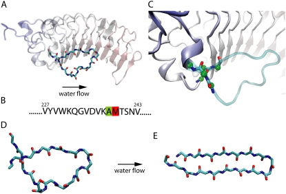
Crystal structures for the 266-residue N-terminal domain of the α-subunit of GPIb (GPIbαN) alone (PDB code 1QYY) and in complex with the A1 domain of vWF(PDB code 1SQ0) have been solved (15–18). Comparison of the two structures reveals that the largest conformational change in GPIbαN upon A1 binding occurs in a 12-residue region of the C-terminal flanking sequence (residues 229–240), the region switches from an originally structureless loop in the unliganded state (see Fig. 1) to a β-hairpin in the liganded state (see Fig. 1 A), hence the name β-switch. The β-hairpin aligns with the central β-sheet of vWF-A1 and forms a major binding interface of the complex. Most GOF or LOF GPIb mutants are located in the β-switch region, including M239V and A238V.
FIGURE 1.
β-switch region of GPIb. (A) α-subunit of GPIb, a platelet surface receptor glycoprotein involved in tethering of blood platelets. Highlighted in solid licorice representation is the actual β-switch, while the remainder of the protein subunit is shown in transparent cartoon representation. (B) Amino-acid sequence of the β-switch with the two amino acids involved in loss and gain of function mutants (see text) highlighted in green and red, respectively. (C) Connection region between β-switch and GPIbα. Backbone of the residues connecting the β-switch to the GPIbα is highlighted in solid licorice representation. Green spheres indicate carbon atoms constrained in the simulation to their crystallographic positions. (D and E) Schematic presentation of the flow-induced transition from a flexible loop β-switch (D) to a β-hairpin β-switch (E).
It has been hypothesized by two of the authors that flow may enhance GPIb-vWF binding by inducing a special type of unstructured→structured conformational transition in the β-switch region of GPIbα, transforming the β-switch from a flexible loop into a β-hairpin (19). Mutants in the β-switch region can change the rate of loop→β-hairpin transition, resulting in GOF or LOF phenotype.
This hypothesis is also supported by molecular dynamics (MD) simulation that used flow to induce conformational changes, termed flow MD (19). In this article, we describe a molecular dynamics algorithm that generates stable flow under constant temperature, and permits long timescale simulations. We observed that the unstructured→structured transition of the β-switch is dominated by the entropy of the protein, and occurs in a stepwise manner. In the following, we describe in detail the two major steps of the conformational transition, namely dihedral rotation and side-group packing. The LOF and GOF mutations are seen to affect the rate of completion of the two steps.
METHODS
System setup
Simulation systems were setup for three different β-switches: the wild-type β-switch (WT), the gain of function mutant M239V (GOF), and the loss of function mutant A238V (LOF). The structure of WT was obtained by truncating residues 227–243 from the crystal structure of unliganded GPIb α-subunit (Protein Data Bank entry code 1QYY) (18). The mutant structures for GOF and LOF were obtained by mutating the corresponding residues of WT using VMD's MUTATER plug-in.
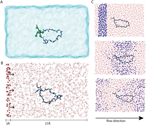
Missing hydrogen atoms were added using the AUTOPSF plug-in of VMD. Neutral terminal patches ACE CT3 were added to the N-terminus and C-terminus. Each protein was solvated in a water box of 60 Å × 30 Å × 30 Å, with one chloride ion added to neutralize the system. All three β-switch-water systems contained ∼9400 atoms each, as shown in Fig. 2 A.
FIGURE 2.
Simulating flow-induced conformational change of the β-switch. The β-switch is shown in solid licorice presentation as in Fig. 1. (A) Simulated β-switch-water system with water shown in transparent blue. The system is confined to a periodic cell of 60 × 30 × 30 Å3. Green spheres indicate constraint β-switch region atoms. (B) Computational method to control constant water flow in the system simulated. Every water molecule with its oxygen x coordinate in the interval [0, 3 Å] experiences a constant force f = 10 pN. Note that the simulated system is periodic in all directions, including the x direction. (C) Demonstration of induced water flow. Shown are three snapshots of the simulated β-switch-water system at times t = 0 (top), 50 ps (middle), and 100 ps (bottom). Water located initially (t = 0) in a stripe along the x axis (see top) is highlighted in blue. One can recognize that the water molecules move along the x axis while their distribution experiences diffusional broadening. Due to the periodicity of the simulated system water molecules that exit the cell on the right are seen to reenter the cell on the left.
Molecular dynamics
Simulations were performed using NAMD 2.6 (20) with periodic boundary conditions imposed. The integration timestep was 1 fs. The CHARMM22 (21,22) force field for protein was used with CMAP correction for backbone dihedrals (23). The particle-mesh Ewald method (24) was employed for full electrostatic calculations, and van der Waals interactions were evaluated using a smooth cutoff (10–12 Å).
To prevent unrealistic translocation and rotation motion of the β-switch backbone due to truncation from the GPIb α-subunit, the Cα atoms of residues 227–228 near the N-terminus and residues 241–243 near the C-terminus were constrained through a harmonic potential with spring constant 1 (kcal/mol Å2) to their crystallographic positions (see Fig. 1 C). The backbone of these residues are not involved in flow-induced H-bond formation (see below), and the relative position of the constrained atoms change very slightly (≤1 Å) between loop (PDB 1QYY) and β-hairpin conformation (PDB 1SQ0). Since only two residues, namely 227 and 228 on the N-terminus, could be constrained without disturbing flow-induced H-bonding, an extra carbon atom (CAY) on the terminal patch of residue 227 was also constrained to prevent unrealistic rotation and to balance the total constraint on both termini (Fig. 2 A). This extra carbon atom is 9 Å away from the nearest flow-induced H-bond, thus constraining it should not bias H-bond formation.
All three systems (WT, GOF, and LOF) were first subjected to 500 steps of energy minimization, then equilibrated in an NPT ensemble for 1 ns. A constant temperature of 310 K was achieved by using a Langevin thermostat coupled to all heavy atoms with damping coefficient γ = 1 ps−1. A Nosé-Hoover Langevin piston was used for pressure control.
All following simulations were performed in an NVT ensemble. A Langevin thermostat was coupled to water oxygen atoms only to minimize the disturbance on protein dynamics. The Langevin damping constant was set to γ = 0.1 ps−1 for constant flow control as described in the next paragraph. The current thermostat setup is shown to be sufficient for maintaining a constant temperature of T = 310 K in all simulations.
Flow control technique
To generate constant water flow along the x axis, every water oxygen atom with its x coordinate in the interval [0, 3] Å (solid region in Fig. 2 B) was pushed along the x direction by a constant force f. Due to the coupling to a Langevin thermostat, each water oxygen is subjected at any moment to a damping force γ v in the direction opposite to its velocity v. The total forces acting on water were seen to quickly (<100 ps) reach a balance after the start of simulation, and a uniform constant water flow resulted.
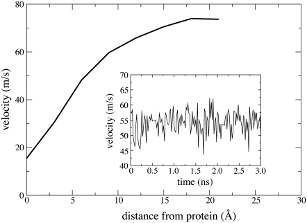
In this study, we choose γ = 0.1 ps−1 and f = 10 pN. The flow velocity resulting from this choice of parameter fluctuates around an average value of ∼50 m/s, as is shown in the inset of Fig. 3. The velocity is chosen to be much lower than the velocity of sound in water (∼1500 m/s), but larger than the average magnitude of random fluctuations (∼20 m/s). The small damping coefficient serves to prevent an inhomogeneous water density distribution at the beginning of the simulation.
FIGURE 3.
Velocity distribution over space and time. The average velocity of a water molecule is found to depend on the molecule's distance d from the protein (for a given molecule, d is the shortest distance of the water oxygen from any protein atom). The water velocity increases monotonously with increasing d from a value of 18 m/s in the contact zone to 77 m/s in the bulk. (Inset) Shown is the velocity  of the simulated water averaged over a 10 Å wide slab water molecules. One can recognize that
  fluctuates over time t around an average value of ∼52 m/s (m/s = 10 Å/ns).
A notable feature of the flow field is the flow velocity as a function of distance d away from the protein, as shown in Fig. 3. Water closer to the protein has a smaller flow velocity, but in close proximity to the protein the flow velocity does not decrease to zero, as expected for a sticky boundary condition. We note that this type of molecular hydrodynamics has been the subject of many molecular dynamics investigations, e.g., those reported in the literature (25–27).
Summary of simulations performed
All three systems (WT, GOF, and LOF) were equilibrated for 38 ns, 10 ns, and 10 ns, respectively, as shown in Table 1 (EqWT, EqGOF, and EqLOF). Two different starting conformations were chosen for each of the three systems from the equilibration trajectories. The starting conformations are shown in stereo views in Supplementary Material in Data S1. For each starting conformation, a set of five independent flow MD simulations were performed. Altogether six different sets of simulations were carried out, as listed in Table 2 (FGOF1, FWT1, FLOF1, FGOF2, FWT2, and FLOF2). Each simulation lasted for 20 ns, or after the β-hairpin was formed and remained stable for 5 ns.
TABLE 1.
Simulations under zero flow condition
| Name | β-Switch type* | Number of runs | Type of simulation | Simulation time (ns) |
|---|---|---|---|---|
| EqWT | WT | 1 | Equilibration | 38 |
| EqGOF | GOF | 1 | Equilibration | 10 |
| EqLOF | LOF | 1 | Equilibration | 10 |
| Pull | WT | 1 | Forced extension | 10 |
All simulations were carried out under zero flow condition.
See Methods.
TABLE 2.
Flow MD simulations performed. Listed are the sets of flow-induced β-hairpin formation simulations performed in this study
| Name | β-Switch type* | Number of runs | β-Hairpin formed | Backbone rotation completed† |
|---|---|---|---|---|
| FWT1 | WT | 5 | 2 | 5 |
| FGOF1 | GOF | 5 | 2 | 3 |
| FLOF1 | LOF | 5 | 3 | 4 |
| FWT2 | WT | 5 | 2 | 4 |
| FGOF2 | GOF | 5 | 4 | 4 |
| FLOF2 | LOF | 5 | 1 | 2 |
Each set of simulations started from a different starting conformation. Altogether 30 simulations were performed. The system setup and simulation conditions are described in Methods. Each simulation lasted for 20 ns, or after a β-hairpin was formed and remained stable for 5 ns.
See Methods.
See Results for details.
Although each set of five simulations shared an identical starting conformation and simulation conditions, the dynamics of the β-switch differed significantly from each other due to random thermal motion, i.e., due to the random number generator used in the thermostat.
For WT, a steered molecular-dynamics simulation (1,2,28) was also performed (See Table 1), in which the β-switch was extended by an external force of 500 pN applied to the heavy atoms of residues 234 and 235 located at the middle of the loop. The overall simulation time in this study is 600 ns.
Data analysis
All data analysis was done with VMD. Flow velocity at time t was estimated as  where
where  is the average x-displacement of water oxygen atoms within a 10 Å wide slab from time t to t + Δt. In this study, we choose Δt = 20 ps, and the slab of water centered at the middle of the box. Water oxygen atoms within the slab experience significant displacement during the time interval [t, t + Δt], but cannot cross the periodic boundary. Flow velocity at distance d from the protein was measured in a similar manner, the only difference being that the average of the x displacement was taken over water molecules with a minimum distance d away from any protein atom.
The conformational energy of protein Ec(t) was measured using the NAMDENERGY plug-in of VMD. Ec(t) is defined as the sum of bond energy, angle energy, dihedral energy, improper energy, and van der Waals interaction energy between protein atoms. Electrostatic interaction energy is not included because the number of water molecules between H-bond partners change significantly during formation of the β-hairpin, such that the dielectric constant changes over time. We will argue in Discussion that measuring Ec(t) is sufficient for our purpose.
The projection area of the protein along a certain axis is determined by assuming that each atom has a projection area of 1 Å2 if not overlapping with other atoms. The overlapping area is discounted properly. Since only the relative ratios of the projection areas were used for analysis, the choice of single atom projection area does not affect the conclusion as long as it is not significantly larger or smaller than this value.
Flow-induced H-bond formation was characterized by measuring the distance between backbone H-bond partners. An H-bond is defined as formed if the distance between interacting oxygen and hydrogen atoms remains <2.5 Å. H-bonds are named by the interacting atoms. For example, 229HN-240O refers to the H-bond formed between the HN atom of residue 229 and the backbone oxygen atom of residue 240.
The rotamer states of Met239 are characterized by c(t) = cos [τ(t)] where τ(t) is the dihedral angle between backbone atoms N, Cα and side-chain atoms Cβ, Cγ of Met239 at time t.
RESULTS
In this section we first compare the different behaviors of the β-switch seen under equilibrium and under flow conditions. We examine then the loop to β-hairpin transition rate of wild-type and mutant β-switches observed in our simulations and describe the molecular details of the transition process. Finally we analyze two key steps observed during the loop→β-hairpin transition.
Different behavior of β-switch under equilibrium and flow
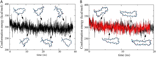
During 38-ns equilibration of the wild-type β-switch, no H-bond between backbone atoms was seen to be formed. Neither did we observe any stable side chain-side chain or side chain-backbone interaction throughout our simulation. The conformation of the β-switch changes significantly from time to time, as is exemplified in the inset of Fig. 4 A.
FIGURE 4.
Flexibility of β-switch loop. An extreme flexibility of the β-switch loop can be demonstrated through monitoring the conformational energy Ec(t) of the loop over time t. Ec(t) includes all energy contributions of the loop due to van der Waals interaction and so-called bond, angle, dihedral, and improper energies (see Methods). Loop flexibility is characterized through constancy of Ec(t) amid time variation of loop conformation (snapshots shown). (A) Ec(t) during 40-ns equilibration. (B) Comparison of Ec(t) during flow-induced β-hairpin formation (red) and during equilibration (black). Note that throughout the β-hairpin formation process there is no difference in Ec(t) as compared to the equilibrium values, implying that the process is entropy-driven.
Despite the high structural flexibility, the conformational energy Ec(t) of the β-switch fluctuates near an average value of 300 kcal/mol during equilibration (Fig. 4 A).
In contrast to the behavior seen in the equilibrium simulations, the backbone of the β-switch quickly approached an elongated, hairpinlike conformation when subjected to constant flow, and stayed close to that conformation throughout the remainder of the simulation. H-bonds were frequently observed to form between backbone atoms, and in half of the simulations the transition to a β-hairpin with six H-bonds was completed (see below). However, the conformational energy Ec(t) of the β-switch during the flow-induced loop→β-hairpin transition showed no noticeable difference when compared to the equilibrium value, as shown in Fig. 4 B.
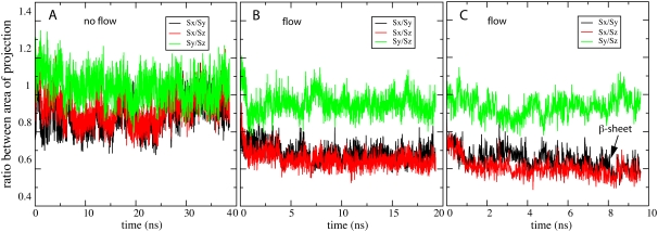
To further characterize the impact of flow on the β-switch dynamics, we measured the projection areas of the β-switch along the x, y, and z axes, denoted as Sx(t), Sy(t), and Sz(t), respectively. The time-dependent behavior of the three ratios, Sx(t)/Sy(t), Sy(t)/Sz(t), and Sy(t)/Sz(t), are plotted in Fig. 5. In equilibrium (Fig. 5 A), the three ratios remained close to unity, which indicates that the overall shape of the β-switch was nearly isotropic. On the other hand, as soon as flow was introduced into the system along the x axis, the projection area Sx(t) decreased, as indicated by the decrease in the two ratios Sx(t)/Sy(t) and Sx(t)/Sz(t), and Sy(t)/Sz(t) still remained close to unity. The decrease in Sx(t) was observed in every flow simulation immediately after the start of the simulation, regardless of whether a β-hairpin was eventually formed. However, in simulations that formed a β-hairpin, Sx(t) was seen to decrease slightly further, as shown in Fig. 5 C.
FIGURE 5.
Quantitative measure of flow-induced β-strand formation. Under zero flow equilibrium conditions, the β-switch remains in an open loop form that is isotropically oriented. The loop geometry can be monitored through measurement of the three projection areas of the loop, Sx(t), Sy(t), and Sz(t), which are projected (along the x, y, and z axis) onto the (y,z)-, (z,x)-, and (x,y)-planes, respectively. Shown in this figure are the ratios between these three areas, namely Sx(t)/Sy(t) (black), Sy(t)/Sz(t) (red), and Sy(t)/Sz(t) (green). (A) Area ratios under zero flow equilibrium conditions. One can recognize that the area ratios converge to unity. (B and C) Area ratios under nonzero flow conditions. Under flow conditions the loop deviates from an isotropic orientation and in certain cases forms a β-hairpin. This behavior can be recognized through the area ratios. (B) Loop behavior under such condition without β-hairpin formation. One can recognize clearly the anisotropy through the area ratio differences. (C) Loop behavior under flow condition with β-hairpin formation. One can recognize again the anisotropy through the area ratio differences; however, the area ratios Sx(t)/Sy(t) (black) and Sx(t)/Sz(t) (red) decreased slightly further upon β-hairpin formation (arrow) as compared to panel B.
Loop to β-hairpin transition under flow
Of the 30 flow MD simulations carried out in this study, 14 succeeded in inducing the loop→β-hairpin transition of the β-switch, as listed in Table 2. The transition was considered to be complete if five H-bonds (229HN-240O, 240HN-229O, 238HN-231O, 231HN-238O, 233HN-236O) were formed and remained stable for 5 ns, while the sixth H-bond (236HN-233O) fluctuated between formed and broken, as illustrated in Fig. 6 E. Among all the six sets of simulations listed in Table 2, FGOF2 had the highest transition rate (4/5), and FLOF2 had the lowest transition rate (1/5).
FIGURE 6.
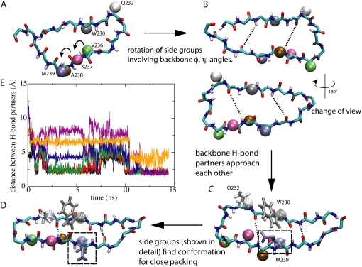
Two major steps of flow-induced β-hairpin formation. (A–D) show the loop to β-hairpin transition process of the β-switch. (A) Initial loop conformation of the β-switch. The backbone of the β-switch is shown in licorice representation as in Fig. 1. Key side-groups are shown as colored spheres; arrows indicate the residues that undergo backbone dihedral (φ, ψ) angle rotation. (B) Completion of step 1 in the loop→β-hairpin transition. Dihedral rotations lead the loop to a geometry in which backbone H-bond partners face each other. Dotted lines indicate two (among a total of six) potential H-bonds. The system is rotated by 180° to offer an alternative view. (C) Second step of transition. Backbone H-bond partners have approached each other more closely, while H-bonding between certain pairs are prevented by unfavorable side-group packing. The unfavorable packing is illustrated for three side-groups, W230, Q232, and M239, which are represented both as spheres and in licorice representation. (D) Formation of the β-hairpin. The β-hairpin conformation is reached through rotamer transition of side-groups as clearly seen for M239 (dashed box). (E) H-bonding during β-hairpin formation. Shown are the distances between H-bonding backbone oxygen and hydrogen atoms. The final β-hairpin can be recognized through a pattern of six H-bonds [229HN-240O (black), 240HN-229O (red), 238HN-231O (green), 231HN-238O (blue), 233HN-236O (violet), and 236HN-233O (yellow)]. One can recognize that all six H-bonds have been formed, except that 236HN-233O (yellow) is weaker than the other five H-bonds.
The flow-induced loop→β-hairpin transition of the β-switch was observed to happen in a stepwise manner consisting of two major steps, as schematically illustrated in Fig. 6. The first step began shortly after the start of the flow. During this step (Fig. 6, A and B), backbone dihedral angles started to rotate in the direction that allowed potential H-bond partners on the two opposite backbone segments to face each other. For simplicity, we will refer to these two segments (residues 229–233 and 236–240) as the two strands, since they eventually will form the two β-strands of the β-hairpin. Side-groups rotated synchronously with the backbone. In several cases the backbone dihedral rotation caused some of the side-groups to pass through the limited space between the two strands. Neighboring side-groups very often rotated as a pair. The most frequently observed rotational motion arose for residue pairs V236-K237 and A238-M239, which have smaller side-groups than the other four residues on the opposite strand.
Toward the end of the first step, the orientation of all the side-groups were close to what they would be in the final β-hairpin state. At the same time, the two strands started to rapidly approach each other allowing initially separated side-groups to come close to one another. In most simulations, two to three H-bonds (229HN-240O, 240HN-229O, and 238HN-231O) were formed at the end of step 1.
In the second step of the transition, which immediately followed the first one, side-groups simultaneously searched for the right conformation to pack tightly with their nearest neighbors. The tight packing of side-groups allowed nearby backbone atoms to be close enough to form stable H-bonds. A typical example is the packing involving bulky side chains of Met239, Trp230, and Gln232, which are highlighted in Fig. 6, C and D. Once tight packing was achieved for most of the side-groups, all six H-bonds were formed (with 236HN-233O weaker than the rest), and the transition to the β-hairpin was completed. The β-hairpin is a stable conformation under flow, and breaking of individual H-bonds after the formation of all six of them was never observed.
The two steps described were common to all the simulations that completed the loop→β-hairpin transition. In the rest of the simulations, failure of transition, with few exceptions, was caused by difficulty in completing one of the two steps, with few exceptions. Moreover, the gain of function and loss of function mutants seemed to increase or decrease the barrier involved in completing one of the two steps (see below). Therefore it is necessary to look more closely into the details of the two steps.
Step 1: Flow-induced backbone dihedral rotation
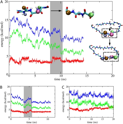
The backbone dihedral rotation induced by flow differs in several respects from the backbone dihedral rotation that occurred spontaneously during equilibration. One significant difference is that flow-induced rotation exhibited clear directionality. All backbone dihedral (φ, ψ) angles on both strands approached the same value. The dihedral angles after rotation not only favored H-bonding between the two strands, but also maximized the distance between backbone heavy atoms, as can be seen in the top insets of Fig. 7 A (distance between the two backbone nitrogen atoms maximized after rotation of a dihedral angle). In other words, flow-induced backbone dihedral angle rotation always increased the length of the backbone in the direction of the flow. In contrast, spontaneous backbone dihedral rotation observed during equilibration randomly increased or decreased backbone length.
FIGURE 7.
First step toward β-hairpin formation. (A) Shown on the right inset is the first step of loop→β-hairpin transition as shown in Fig. 6. The key dihedral rotations involved in the transition are highlighted in dashed boxes and shown enlarged in the top inset. The figure shows the time (t) behavior of the angle [Eangle(t), green], dihedral [Edihedral(t), red], and total [Etot(t) = Eangle(t) + Edihedral(t), blue] energies of the relevant backbone segment. One can recognize through the energy traces the dihedral rotation step occurring during the time interval depicted by a gray bar. (B) Time behavior of the energies Eangle(t), Edihedral(t), and Etot(t) in a simulation which induced β-hairpin formation through stretching the loop (see Methods). One can recognize force-induced dihedral rotation through concerted change in Eangle(t) and Edihedral (gray bar). (C) Time behavior of energies Eangle(t), Edihedral(t), and Etot(t) during equilibration. In contrast to panels A and B, no concerted change in energy is observed; also, the energy Etot(t) does not decrease significantly.
Another unique feature of flow-induced rotation is a clear pattern of concerted variation in the backbone angle and dihedral energy. In Fig. 7 A, one can recognize two dihedral rotation events by two bumps in the dihedral energy (red) of the relevant backbone segment. Notably, angle energy (green) of the same backbone segment increased shortly before the rotation started, and decreased immediately after it was completed. The sum of the two energy terms, shown in blue, decreased after the completion of each rotation event. Such concerted motion was not observed in case of spontaneous rotation in equilibrium (Fig. 7 C).
Interestingly, the features of flow-induced rotation, including high directionality and concerted energy change, were reproduced in steered molecular dynamics simulation “Pull” (see Table 2), in which the backbone of the β-switch in the loop conformation was extended by external force along the x-direction (simulation details described in Methods). The concerted change of energy in simulation “Pull” is shown in Fig. 7 B.
In one set of flow simulations performed on LOF, FLOF2, the backbone dihedral rotation step was significantly harder to complete as compared to the other simulations. When compared to a set of simulations on WT, FWT2, in which most of the residues underwent similar degrees of rotation, we noticed that in FLOF2 the rotation motion was hindered by the side-group of the mutated residue Val238.
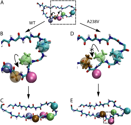
Fig. 8 demonstrates the detailed difference between the dynamics of the two systems. In both cases, backbone dihedral rotation caused the side-group of Val236 to rotate around one of the strands. For WT, Val236 passed easily through the space between side-groups of Ala238, Val234, and the nearby backbone segment (Fig. 8, B and C). However, in LOF, mutation Val238 rendered the space smaller; the side-group of Val236 experienced steric collisions when trying to pass through the space, which, in most cases, prevented the completion of the backbone rotation motion (Fig. 8, D and E). As a result, two of the H-bonds (231HN-238O, 233HN-236O) could not form because the abnormal dihedral conformation prevented the H-bond partners to face each other.
FIGURE 8.
Backbone dihedral rotation in wild-type β-switch and in its A238V mutant. (A) Schematic illustration of the β-switch before backbone dihedral rotation. Side-groups are represented as spheres, and colored as in Fig. 6. Bent arrows indicate side-groups that rotate together with the backbone dihedral. (B) Side-group rotation of wild-type β switch. Shown here is an enlarged snapshot of protein motion in the region highlighted in the dashed box in panel A. Key side-groups are shown both as spheres and in licorice representations. One can see that Val236 (green) is able to pass through the interval between Ala238 (brown) and Val234 (cyan). (C) Structure of wild-type β-switch after completion of side-group rotation. (D) Side-group rotation seen in the β-switch mutant A238V in the same region as panel B. The A238V mutation decreases the interval between residues Ala238 (brown) and Val234 (cyan), and does not allow Val236 to pass through easily. (E) Structure of β-switch mutant A238V at the end of simulation. Rotation of Val236 is not completed, which results in an abnormal backbone dihedral that prevents H-bond formation, as highlighted in the dashed box.
Different random starting conformations require different degrees of backbone rotation to complete step 1 of the loop→β-hairpin transition. The starting structure of simulation set FLOF1 required less backbone dihedral rotation than did set FLOF2; thus, the completion rate of step 1 was higher (see Table 2).
Step 2: Packing of side-groups
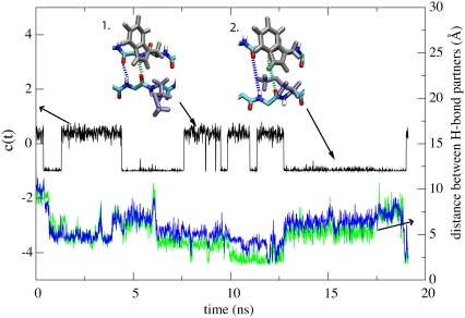
As stated above, the second step in the loop→β-hairpin transition can be illustrated by the close packing of residues Met239 and Trp230, as shown in Fig. 9.
FIGURE 9.
Second step toward β-hairpin formation. The second reaction step involves reorientation of side-group Met239. The reorientation can be characterized by c(t) = cos(τ(t)) of the dihedral angle τ(t) between backbone atoms N, Cα and side-chain atoms Cβ, Cγ of Met239. The trace of c(t), plotted in black, shows transitions between two rotamer states of Met239, snapshots of which are provided as insets. Once Met239 is in rotamer state 2 (defined in the figure) hydrogen-bond formation between potential H-bond partners 238HN-231O and 231HN-238O is severely disrupted. The H-bond formation can be monitored through the distances d(238HN-231O) and d(231HN-238O) shown in blue and green traces, respectively (right abscissa); d values larger than 2.5 Å correspond to lack of hydrogen bonding. The distances d(238HN-231O) and d(231HN-238O) are illustrated in the top insets through dashed lines of corresponding color.
The side-group of Met239 can have two different conformations, illustrated in the top inset of Fig. 9. We refer to these conformations as rotamer state 1 and rotamer state 2. In rotamer state 1, the orientation of the side-group is perpendicular to the backbone. In rotamer state 2, it is parallel. Met239 was observed to frequently shift back and forth between the two rotamer states during flow simulations; in contrast, the side-group of Trp230 remains primarily near one steady conformation.
Trp230 in its usual conformation can only pack tightly with both Gln232 and Met239 when Met239 is in rotamer state 1. The tight packing among the three side-groups will allow the H-bonds 238HN-231O, 231HN-238O to form and remain stable. When Met239 is in rotamer state 2, interaction between side-groups of Trp230, Gln232, and Met239 can severely disrupt H-bonds 238HN-231O and 231HN-238O, causing the two strands to move away from each other. The relation between side-group conformation of Met239 and related H-bonds is demonstrated in Fig. 9, in which the H-bonds are seen to break after Met239 shifted to rotamer state 2 at ∼12 ns.
In simulation sets FWT1 and FWT2, altogether nine simulations completed step 1, but only four simulations formed a β-hairpin within 20 ns. In three out of five simulations that failed the transition, H-bonding was disrupted by Met239 in rotamer state 2.
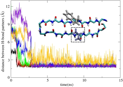
However, in GOF, residue 239 was mutated from methionine into valine, which is much easier to pack tightly with Trp230 due to its shorter side-group, as shown in the inset of Fig. 10. As a result, in seven simulations that completed step 1, six simulations formed a β-hairpin (FGOF1, FGOF2). In some of the simulations, the loop→β-hairpin transition was completed in <3 ns, as shown in Fig. 10.
FIGURE 10.
Formation of β-hairpin in the M239V gain of function mutant (GOF). Shown are distances between potential H-bond partners: d(229HN-240O (black), d(240HN-229O (red), d(238HN-231O (green), d(231HN-238O (blue), d(233HN-236O (yellow), and d(236HN-233O (violet). One can recognize that in the simulation represented in this figure β-switch mutant M239V forms six hydrogen bonds at time t ≥ 3 ns. During the remainder of the simulation, i.e., for 3 ns ≤ t ≤ 15 ns, the hydrogen bonds remained intact and the mutant assumed a β-hairpin conformation as shown in the inset. The dashed box indicates the mutation site.
DISCUSSION
In this section we will address three key questions:
First, what prevents spontaneous loop→β-hairpin transitions of the β-switch from happening in the absence of flow?
Second, how does unidirectional flow drive a disordered structureless protein segment to rearrange itself into an ordered conformation, i.e., into a β-hairpin?
Third, what determines the loop→β-hairpin transition rate under flow?
We also discuss the limitations of this study and opportunities for future research.
Entropy prevents spontaneous loop to β-hairpin transition in equilibrium
Evidence from experiment and simulation has shown that the β-switch almost never adopts the β-hairpin conformation in equilibrium, which indicates the existence of a free energy barrier separating loop state and β-hairpin states. Our results suggest that this barrier is predominantly entropic. Indeed we have already shown in the previous section that the conformational energy Ec(t) does not differ significantly between loop and β-hairpin state.
From Fig. 4 we see that the β-switch is very flexible and can adopt a large number of different loop conformations in equilibrium. In contrast, there is essentially only one β-hairpin conformation. Although entropy is hard to measure directly, the large difference in the number of accessible conformations is clear evidence for a significant entropic difference between the two states. Therefore, we conclude that the flexibility of the β-switch ensures that the loop state is entropically more favorable than the β-hairpin state, thereby preventing spontaneous transitions from happening in equilibrium.
Electrostatic interaction is not included in Ec(t), but it is unlikely to favor the loop state. No stable interaction is observed among the three charged residues in the β-switch during equilibrium. Neither did we observe any stable electrostatic interaction between charged side-groups and backbone. Moreover, stable backbone H-bonding only occurred in the later stage of β-hairpin formation, i.e., electrostatic interaction should only favor the transition toward the β-hairpin, rather than preventing it. Hydrophobic residues were not able to form a stable core during equilibration, and no significant increase in exposed hydrophobic surface area was observed in the flow MD simulations.
Mechanism of flow-induced loop to hairpin transition
We observed in our simulations that when the β-switch was subjected to unidirectional water flow, it rearranged itself from a random starting conformation toward a β-hairpin conformation. The mechanism behind this process is revealed at least partly by studying two steps of β-hairpin formation, namely flow-induced backbone dihedral rotation and side-group packing.
The backbone dihedral rotation in Step 1 is caused by water dragging and extending the two strands of the β-switch in the direction of the flow. As can be seen from the top inset of Fig. 7, upon extension the dihedrals are forced to rotate in the direction that increases the length of the backbone. When there is a barrier preventing this rotation, the extension force causes the angle energy contained in the backbone to increase, until the barrier is overcome. The barrier stems from backbone dihedral energy and from steric hindrance.
We found that the backbone dihedral rotation is also seen in forced extension of the β-switch, i.e., without flow but with pulling. This proves that the dragging effect of the flow induces the rotation. Concerted increase and decrease in angle and dihedral energies in both flow and extension simulations further support the idea that barriers during the rotation motion are overcome by forced extension of the backbone, i.e., the loop→β-hairpin transition is brought about by extension-torsional motion coupling.
In flow simulations, the dragging force stems from water molecules colliding with the protein. From the velocity distribution (Fig. 3), one can clearly see that flow is slowed down near the protein, and that water molecules that collide with protein atoms have a nonzero average velocity.
Flow is also critical for Step 2 of the loop→β-hairpin transition. As is shown in Fig. 5, B and C, under the impact of flow, the β-switch approached a state with small Sx/Sy and Sx/Sz ratios, which means that the loop was being stretched narrow by the flow. As a result, residues originally separated on the two strands of the loop were brought together and remained close to each other. This ensures that whenever pairs of side-groups were in suitable conformations, tight-packing between side-groups and H-bonding between backbones can be quickly achieved.
In conclusion, we found that flow can induce transition of the β-switch toward β-hairpin conformation.
Mutations to the β-switch alter the transition rate
Experiments have shown that mutations in the β-switch region of GPIB can increase or decrease its binding affinity with the vWF under the same flow condition. Based on our simulations, we suggest that those mutations affect the binding affinity by changing the probability of flow induced loop→β-hairpin transition of the β-switch.
Simulation set FLOF2 reveals the loss of function mutation A238V to significantly increase the barrier for completion of step 1 in β-hairpin formation. The mutated valine has a larger side-group than alanine, which results in increased steric collision with nearby residues during backbone dihedral rotation, preventing the rotation to complete. The gain of function mutant M239V increased the β-hairpin formation rate in simulation set FGOF2, because the mutated valine has a shorter side chain and is easier to pack tightly with its neighbors. It is likely that the mutation results in a faster β-hairpin transition as compared to the transition in the wild-type, since all simulations lasted for 20 ns at most.
Limitations of this study
One major limitation of this study is the relatively small number of starting conformations explored in the simulations of flow-induced β-hairpin formation. Simulations of the same system with different starting conformation displayed different rates of the loop→β-hairpin transition, e.g., in case of FLOF1 and FLOF2 (Table 2). Due to the limitation in computational resources, only two starting conformations could be investigated for each system so far. Better sampling is clearly desirable.
Another limitation is the total number of simulations performed. In this study, only behavior repeatedly observed in our simulations has been reported. It is likely that there exist other features of the β-switch that unfortunately did not occur frequently enough to be noticed. For example, rotation of the pair of side-groups A238-M239 happened more frequently in the direction that allows the smaller alanine side-group to pass between the two strands of the loop, since the larger methionine side-group often prevented attempted rotation in the opposite direction. We have observed that mutation M239V permitted rotation in the opposite direction in some simulations. We suggest that enabling rotation in both directions increases the probability of completing step 1. However, we did not observe the opposite direction rotation frequently enough to support the hypothesis.
In all flow MD simulations, we assumed a flow velocity of 50 m/s, which is fast compared to typical blood flow velocity of ∼1 m/s inside arteries. Blood flow in small blood vessels and near vessel walls could be even slower, with typical velocities as low as 10−6 m/s. Using a higher flow velocity increased the speed of the loop→β-hairpin transition, allowing the process to happen on the timescale accessible to our computer simulation. This practice is similar to using a large force in SMD simulations to accelerate the conformational transitions in proteins observed in atomic force microscopes at smaller forces (1,2,29). However, the mechanism of flow-induced conformational change proposed in this study does not rely on the particular flow velocity chosen for the simulations, and therefore should be valid under physiological flow condition.
The orientation of the β-switch with respect to the flow was fixed in the simulations by harmonic constraints on its terminal region. This choice of orientation is based on the assumption that the roughly cylindrical GPIbα subunit will always align its long axis with the direction of flow, as indicated in Fig. 1. The N-terminus of GPIbα is connected to the surface of the platelet through a long flexible stalk (30), allowing GPIbα to easily align itself with flow in different directions.
Finally, in this study we only simulated the truncated isolated β-switch under uniform constant flow conditions. The realistic flow field near the β-switch, as well as the dynamics of the β-switch, could be affected by the whole α-subunit of GPIb.
Opportunities for future work
The impact of flow on the dynamics of biomolecules is a relatively new field of study. We have demonstrated here that shear flow can induce loop→β-hairpin transition in the β-switch region, allowing the GPIb protein to act as a molecular flow sensor. Since flow is a very common phenomenon in biological systems, it is interesting to ask in future studies whether there exist other biomolecules that also serve as molecular flow sensors, and whether they adopt designs similar to the β-switch.
Moreover, although conformational change of protein in response to external perturbation is a well-studied process, past studies usually involve structured→unstructured transitions, for example, forced unfolding of protein secondary structure. Here we have shown that the opposite process, e.g., an unstructured→structured transition, is also possible and can play an important role in biological processes. In forced unfolding of protein secondary structure, the critical element is the energy involved in breaking of H-bonds. For the opposite process, at least in the case of the β-switch, the conformational change is dominated by entropy.
It would be interesting to see whether unstructured→structured transitions also occur in other proteins carrying out different functions. Furthermore, is a loop→β-hairpin transition the only form of this type of transitions? Is it possible for a flexible chain to form other secondary structures such as α-helices under flow or other form of perturbation? We expect that these unanswered questions will lead to much future work.
The most obvious issues to be investigated in future studies of GPIb protein are MD simulations of the β-switch in the context of the entire protein and in the case of much reduced flow. Such simulations could address how far the protein environment favors β-hairpin formation and how the rate of the loop→β-hairpin transition scales with the flow velocity, which are both essential for judging the feasibility of the suggested mechanism.
SUPPLEMENTARY MATERIAL
To view all of the supplemental files associated with this article, visit www.biophysj.org.
Supplementary Material
Acknowledgments
The authors thank Professor Aleksei Aksimentiev for insightful discussion. The authors also acknowledge computation on the University of Illinois Turing Xserve Cluster.
All images and most molecular dynamics trajectory analyses were carried out with the Visual Molecular Dynamics (VMD) software (31).
This work was funded by the National Institutes of Health grant No. P41-RR05969 (K.S.) and HL091020 (C.Z.). The authors gladly acknowledge supercomputer time provided by the Pittsburgh Supercomputing Center and the National Center for Supercomputing Applications via Large Resources Allocation Committee grant No. MCA93S028.
Editor: Ron Elber.
References
- 1.Lu, H., B. Isralewitz, A. Krammer, V. Vogel, and K. Schulten. 1998. Unfolding of titin immunoglobulin domains by steered molecular dynamics simulation. Biophys. J. 75:662–671. [DOI] [PMC free article] [PubMed] [Google Scholar]
- 2.Sotomayor, M., and K. Schulten. 2007. Single-molecule experiments in vitro and in silico. Science. 316:1144–1148. [DOI] [PubMed] [Google Scholar]
- 3.Lou, J., T. Yago, A. G. Klopocki, P. Mehta, W. Chen, V. I. Zarnitsyna, N. V. Bovin, C. Zhu, and R. P. McEver. 2006. Flow-enhanced adhesion regulated by a selectin interdomain hinge. J. Cell Biol. 174:1107–1117. [DOI] [PMC free article] [PubMed] [Google Scholar]
- 4.Zhu, C., T. Yago, J. Lou, V. I. Zarnitsyna, and R. P. McEver. 2008. Mechanisms for flow-enhanced cell adhesion. Ann. Biomed. Eng. 36:604–621. [DOI] [PMC free article] [PubMed] [Google Scholar]
- 5.Savage, B., E. Saldivar, and Z. M. Ruggeri. 1996. Initiation of platelet adhesion by arrest onto fibrinogen or translocation on von Willebrand factor. Cell. 84:289–297. [DOI] [PubMed] [Google Scholar]
- 6.McEver, R. P. 2001. Adhesive interactions of leukocytes, platelets, and the vessel wall during hemostasis and inflammation. Thromb. Haemost. 86:746–756. [PubMed] [Google Scholar]
- 7.Weiss, J. H. 1975. Platelet physiology and abnormalities of platelet function. N. Engl. J. Med. 293:580–588. [DOI] [PubMed] [Google Scholar]
- 8.Savage, H., M. Cyrklaff, G. Montoya, W. Kühlbrandt, and I. Sinning. 1996. Two-dimensional structure of light harvesting complex II (LHII) from the purple bacterium Rhodovulum sulfidophilum and comparison with LHII from Rhodopseudomonas acidophila. Structure. 4:243–252. [DOI] [PubMed] [Google Scholar]
- 9.Doggett, T., G. Girdhar, A. Lawshe, J. Miller, I. Laurenzi, S. Diamond, and T. Diacovo. 2003. Alterations in the intrinsic properties of the GPIbα-vWF tether bond define the kinetics of the platelet-type von Willebrand disease mutation, Gly233Val. Blood. 102:152–160. [DOI] [PubMed] [Google Scholar]
- 10.Morii, H., T. Takenawa, F. Arisaka, and T. Shimizu. 1997. Identification of kinesin neck region as a stable α-helical coiled coil and its thermodynamic characterization. Biochemistry. 36:1933–1942. [DOI] [PubMed] [Google Scholar]
- 11.Russell, S., and G. Roth. 1993. Pseudo-von Willebrand disease: a mutation in the platelet glycoprotein Ib α-gene associated with a hyperactive surface receptor. Blood. 81:1787–1797. [PubMed] [Google Scholar]
- 12.Kumar, R. A., J. Dong, J. A. Thaggard, M. A. Cruz, and J. Lopez. 2003. Kinetics of GPIbα-vWF-a1 tether bond under flow: effect of GPIbα mutations on the association and dissociation rates. Biophys. J. 85:4099–4109. [DOI] [PMC free article] [PubMed] [Google Scholar]
- 13.Miller, J., D. Cunningham, V. Lyle, and C. Finch. 1991. Mutation in the gene encoding the α-chain of platelet glycoprotein Ib in platelet-type von Willebrand disease. Proc. Natl. Acad. Sci. USA. 88:4761–4765. [DOI] [PMC free article] [PubMed] [Google Scholar]
- 14.Murata, M., S. R. Russell, Z. M. Ruggeri, and J. Ware. 1993. Expression of the phenotypic abnormality of platelet-type von Willebrand disease in a recombinant glycoprotein Ib α-fragment. J. Clin. Invest. 91:2133–2137. [DOI] [PMC free article] [PubMed] [Google Scholar]
- 15.Dumas, J., R. Kumar, T. McDonagh, F. Sullivan, M. Stahl, W. Somers, and L. Mosyak. 2004. Crystal structure of the wild-type von Willebrand factor a1-glycoprotein Ibα complex reveals conformation differences with a complex bearing von Willebrand disease mutations. J. Biol. Chem. 279:23327–23334. [DOI] [PubMed] [Google Scholar]
- 16.Huizinga, E., S. Tsuji, R. Romijn, M. Schiphorst, P. de Groot, J. Sixma, and P. Gros. 2002. Structures of glycoprotein Ibα and its complex with von Willebrand factor a1 domain. Science. 297:1176–1179. [DOI] [PubMed] [Google Scholar]
- 17.Uff, S., J. Clemetson, T. Harrison, K. Clemetson, and J. Emsley. 2002. Crystal structure of the platelet glycoprotein Ib(α) N-terminal domain reveals an unmasking mechanism for receptor activation. J. Biol. Chem. 277:35657–35663. [DOI] [PubMed] [Google Scholar]
- 18.Varughese, K., Z. Ruggeri, and R. Celikel. 2004. Platinum-induced space-group transformation in crystals of the platelet glycoprotein Ibα N-terminal domain. Acta Crystallogr. D Biol. Crystallogr. 60:405–411. [DOI] [PubMed] [Google Scholar]
- 19.Lou J., and C. Zhu. 2008. Flow induces loop to β-hairpin transition on the β-switch of platelet glycoprotein Ibα-A flow MD study. Proc. Natl. Acad. Sci. USA. In press. [DOI] [PMC free article] [PubMed]
- 20.Phillips, J. C., R. Braun, W. Wang, J. Gumbart, E. Tajkhorshid, E. Villa, C. Chipot, R. D. Skeel, L. Kale, and K. Schulten. 2005. Scalable molecular dynamics with NAMD. J. Comput. Chem. 26:1781–1802. [DOI] [PMC free article] [PubMed] [Google Scholar]
- 21.MacKerell, A. D., Jr., D. Bashford, M. Bellott, J. R. L. Dunbrack, J. Evanseck, M. J. Field, S. Fischer, J. Gao, H. Guo, S. Ha, D. Joseph, L. Kuchnir, K. Kuczera, F. T. K. Lau, C. Mattos, S. Michnick, T. Ngo, D. T. Nguyen, B. Prodhom, B. Roux, M. Schlenkrich, J. Smith, R. Stote, J. Straub, M. Watanabe, J. Wiorkiewicz-Kuczera, D. Yin, and M. Karplus. 1992. Self-consistent parameterization of biomolecules for molecular modeling and condensed phase simulations. FASEB J. 6:A143. [Google Scholar]
- 22.MacKerell, A., Jr., D. Bashford, M. Bellott, R. L. Dunbrack, Jr., J. Evanseck, M. J. Field, S. Fischer, J. Gao, H. Guo, S. Ha, D. Joseph, L. Kuchnir, K. Kuczera, F. T. K. Lau, C. Mattos, S. Michnick, T. Ngo, D. T. Nguyen, B. Prodhom, I. W. E. Reiher, B. Roux, M. Schlenkrich, J. Smith, R. Stote, J. Straub, M. Watanabe, J. Wiorkiewicz-Kuczera, D. Yin, and M. Karplus. 1998. All-atom empirical potential for molecular modeling and dynamics studies of proteins. J. Phys. Chem. B. 102:3586–3616. [DOI] [PubMed] [Google Scholar]
- 23.Buck, M., S. Bouguet-Bonnet, R. W. Pastor, and A. D. MacKerell. 2006. Importance of the CMAP correction to the CHARMM22 protein force field: dynamics of hen lysozyme. Biophys. J. 90:L36–L38. [DOI] [PMC free article] [PubMed] [Google Scholar]
- 24.Darden, T., D. York, and L. Pedersen. 1993. Particle mesh Ewald. An N·log(N) method for Ewald sums in large systems. J. Chem. Phys. 98:10089–10092. [Google Scholar]
- 25.Soong, C., T. Yen, and P. Tzeng. 2007. Molecular dynamics simulation of nanochannel flows with effects of wall lattice-fluid interactions. Phys. Rev. E Stat. Nonlin. Soft Matter Phys. 76:036303–036317. [DOI] [PubMed] [Google Scholar]
- 26.Fan, X., N. Phan-Thien, N. T. Yong, and X. Diao. 2002. Molecular dynamics simulation of a liquid in a complex nano channel flow. Phys. Fluids. 14:1146–1153. [Google Scholar]
- 27.Hu, Y. Z., H. Wang, and Y. Guo. 2006. Molecular dynamics simulation of Poiseuille flow in ultra thin film. Tribotest. 1:301–310. [Google Scholar]
- 28.Isralewitz, B., M. Gao, and K. Schulten. 2001. Steered molecular dynamics and mechanical functions of proteins. Curr. Opin. Struct. Biol. 11:224–230. [DOI] [PubMed] [Google Scholar]
- 29.Berndt, M. C., Y. Shen, S. Dopheide, E. Gardiner, and R. Andrews. 2001. The vascular biology of the glycoprotein Ib-Ix-V complex. Thromb. Haemost. 86:178–188. [PubMed] [Google Scholar]
- 30.Lopez, J., D. Chung, K. Fujikawa, F. Hagen, T. Papayannopoulou, and G. Roth. 1987. Cloning of the α-chain of human platelet glycoprotein Ib: a transmembrane protein with homology to leucine-rich α2-glycoprotein. Proc. Natl. Acad. Sci. USA. 84:5615–5619. [DOI] [PMC free article] [PubMed] [Google Scholar]
- 31.Humphrey, W., A. Dalke, and K. Schulten. 1996. VMD—visual molecular dynamics. J. Mol. Graph. 14:33–38. [DOI] [PubMed] [Google Scholar]
Associated Data
This section collects any data citations, data availability statements, or supplementary materials included in this article.


