Abstract
The amide I vibrational mode, primarily associated with peptide-bond carbonyl stretches, has long been used to probe the structures and dynamics of peptides and proteins by infrared (IR) spectroscopy. A number of ab initio-based amide I vibrational frequency maps have been developed for calculating IR line shapes. In this paper a new empirical amide I vibrational frequency map is developed. To evaluate its performance, we applied this map to a system of isotope-edited CD3-ζ membrane peptide bundles in aqueous solution. The calculated 2D-IR diagonal linewidths vary from residue to residue and show an asymmetric pattern as a function of position in the membrane. The theoretical results are in fair agreement with experiments on the same system. Through analysis of the computed frequency time-correlation functions, it is found that the 2D-IR diagonal widths are dominated by contributions from the inhomogeneous frequency distributions, from which it follows that these widths are a good probe of the extent of local structural fluctuations. Thus the asymmetric pattern of linewidths follows from the asymmetric structure of the bundle in the membrane.
II. INTRODUCTION
One- and two-dimensional infrared (IR) experiments are very successful at providing information about molecular structure and dynamics in condensed phase systems,1-7 since vibrational frequencies are sensitive to local environments. Thus, for example, such experiments have proven to be excellent for determining average conformations of peptides and proteins in solution, and for probing conformational and solvent dynamics.8-32 These experiments typically involve the amide I band, which is due primarily to carbonyl stretches of peptide bonds. One feature of these experiments is that since there is essentially one peptide bond per amino acid residue, some of the relevant carbonyls are in close physical proximity, and hence their stretches are coupled. Since the coupling depends on protein configuration, this leads to characteristic bands for different secondary structures. Thus, for example, α-helix regions absorb near 1650 cm-1, while β-sheets absorb at 1620 and 1675 cm-1. This variation of amide I frequency clearly leads to a useful structural tool.33-40
On the other hand, this coupling makes the spectroscopic signatures less local, since now the relevant vibrational eigenstates are delocalized excitons. Moreover, this coupling significantly complicates the theoretical modeling of amide I spectroscopy due to the excitonic nature of the instantaneous eigenstates. For both of these reasons researchers have employed isotope labelling as a way to decouple the system. Thus, for example, if one particular carbonyl is labeled with 13C and 18O, its frequency is shifted significantly (some 60 cm-1) from the local frequencies of the unlabeled carbonyls,41 which is somewhat larger than the largest vibrational coupling, meaning that the labeled mode is shifted outside of the exciton band, and hence functions well as a local chromophore. Therefore this scheme provides an excellent probe of the structure and dynamics of local environments, and has been used by a number of groups.14,17,19-22,24,25,28,30,41,42
From a theoretical perspective, one challenge for modeling IR spectroscopy of peptides and proteins is to develop an efficient and accurate method for obtaining local amide I frequencies for given microscopic environments. Such methods lead to what have been called “vibrational frequency maps”. In this context it is useful to consider a model system, dilute N-methyl-acetamide (NMA) in water. NMA is a peptide bond capped with methyl groups, and since there is no conformational flexibility in this molecule, the vibrational frequency map for the amide I stretch is determined by configurations of nearby water molecules. Actually, because the strong absorption in liquid water at about 1600 cm-1 (due to the water bend) overlaps considerably with the amide I stretch, experiments are typically performed in D2O, leading to deuteration of the amino hydrogen. Therefore the system most often studied is dilute singly-deuterated NMA (NMAD) in liquid D2O.
From a fundamental point of view, the vibrational frequency of a local mode is obtained from an analysis of the ground-state Born-Oppenheimer potential. If the local mode is sufficiently high in frequency, the relevant Born-Oppenheimer surface involves fixed configuration of these other nuclei. In principle, then, for a given D2O configuration, one could perform electronic structure calculations, for all electrons in the NMAD and water molecules, and assuming that the vibration is sufficiently harmonic, perform a local harmonic analysis to obtain the amide I frequency. To calculate the vibrational spectroscopy, one could perform a classical molecular dynamics (MD) simulation of NMAD in D2O, and at each time step obtain the amide I frequency as above, producing a frequency trajectory, from which one can use now-standard techniques43 to obtain absorption and two-dimensional-IR (2D-IR) spectra.
The problem, of course, is that it is not possible to perform the required number of electronic structure calculations with sufficient speed and accuracy to implement the above program. One approach that preserves the spirit of the above, but renders it tractable, involves performing electronic structure calculations with fewer water molecules, only a few hundred times. Thus, for example, from the MD simulation one can extract representative clusters of the NMAD molecule surrounded by only the nearest water molecules, and do electronic structure calculations on these clusters. As above, since the amide I frequency is a functional of the positions of the water nuclei, the relevant frequency map now involves all of these nuclear positions, but the explicit function of these positions is unknown. One way to proceed is to assume that the map instead involves a collective coordinate, and then use the calculated frequencies to determine the best coordinate and map. Thus, for example, our and Cho's group and others have considered the collective coordinate to be the electric field or potential from the point-charge representation of the surrounding water molecules, evaluated at several sites within the NMAD molecule.44-49 Alternatively, Mukamel and Jansen and coworkers have developed related electric-field maps that are obtained from electronic structure and frequency calculations of the NMAD in an inhomogeneous electrostatic field.50,51 In any of these approaches, the idea is to use the map in the course of a classical simulation of the liquid to produce the required frequency trajectory. Others have adopted some of these maps for more complicated situations.52-54
Although these vibrational frequency maps for NMAD have been useful, and seem to perform satisfactorily, there still exist several concerns. Since the maps are constructed from ab initio calculations, the effects of the level of theory and basis set have to be examined carefully to ensure accurate results. When NMAD/D2O clusters are used in the calculations, the cluster sizes are rather limited, which neglects possible effects from outer solvation shells. Therefore when one implements the map in an MD simulation, it is also not clear how the results will extrapolate to the liquid. And in this context it is not clear if the electric field or potential should be calculated for molecules within some spatial cut-off, or (in the case of the electric field) from the Ewald summation field. (We note that for the vibrational spectroscopy of water these issues have been dealt with to some extent by performing electronic structure calculations on water clusters in the electrostatic field of all the remaining molecules within half the box length, and then in the simulation the electric field used in the map is calculated up to this same cutoff.55-57)
In this paper we adopt a somewhat different approach; we use ab initio calculations to suggest a form for the frequency map, but then determine the parameters of the map by comparing to spectroscopic experiments. In particular, the coefficients for the electric fields in the map are determined empirically by minimizing the differences between the calculated and experimental peak positions and linewidths in the absorption spectrum for the amide I mode of NMAD in D2O. Although an empirical treatment certainly lacks theoretical elegance, this approach circumvents the basis set, theory level, and cluster size issues inherent in the quantum chemistry calculations. In our empirical approach, a cutoff of 20 Å is used in both the parameterization and implementation, so there is no ambiguity regarding which molecules to include in the electric field calculation, and no extrapolation issue. The development of a frequency map based on experimental results was also implemented by Smith and coworkers, who related the OH stretch frequency of HOD in D2O to the electric field by fitting the frequency distribution to the experimental Raman spectra.58
An additional difficulty with any of these frequency maps has to do with transferability to other solvent environments. That is, they are parameterized for liquid water, and so it is not clear to what extent they will be valid for other solvents (although in this context we note that two electrostatic maps have been tested in solvents other than water, with satisfactory results51,59). Moreover, there is the question of transferability of an NMA map to peptides and proteins in solution (or in membranes). In a peptide or protein in solution the local amide I frequencies depend on peptide/protein (as well as solvent) conformations.20,31,52,60-66 One possibility is that this conformational dependence can be adequately represented by electrostatics, using the NMAD/D2O frequency map.20,60,63,64 A second possibility is that this is not adequate, and that instead much of this conformational dependence needs to be treated explicitly, for example through quantum chemistry calculations involving dependences on nearby ϕ and ψ dihedral angles.52,65,66 Thus the important issues of transferability of NMAD maps to different solvent (including membrane) environments, and the appropriateness of using NMA electrostatic maps for the peptide/protein conformational dependence, both need to be studied systematically.
Leaving this systematic study for the future, in this paper we simply implement the empirical NMA map for a complicated peptide system, the trans-membrane CD3-ζ peptide bundle. In biological cells, after antigen recognition triggers T cells, the biochemical signals are transduced from the cell surface to the interior by CD3 and ζ proteins in the T-cell receptor complex.67,68 CD3 and ζ proteins are identical in all T cells, consistent with signaling rather than recognizing functions. The results from a comprehensive site-specific IR dichroism study on the trans-membrane domain of the ζ proteins, herein and elsewhere called the CD3-ζ peptides, have suggested the formation of a tetrameric CD3-ζ bundle in lipid bilayers.69,70
In the site-specific IR experiments isotope-edited samples were prepared by 13C and 18O labelling 11 different single residues. These 11 isotope labels extend along the 21-residue peptide bundle, with environment changing from a more hydrophilic membrane surface, to the center of the hydrophobic lipid bilayer and to the hydrophilic surface on the other side of the membrane. 2D-IR studies of these isotope-edited samples have also shown that the average frequency and 2D-IR diagonal width of an amide I mode are sensitive to its position in the transmembrane peptide.21,22 This system therefore provides an interesting case on which to test the developed map. We find that our calculated amide I frequencies and the 2D-IR diagonal and anti-diagonal widths are in fair agreement with experiment. Through analysis of the computed 2D-IR spectra, we find that the 2D-IR diagonal widths in this system are dominated by contributions from the inhomogeneous frequency distributions, which means that they are most sensitive to the ensemble of local structural fluctuations. For the CD3-ζ system considered herein, this realization allows us to interpret and understand the asymmetric residue dependence of the 2D-IR diagonal widths.
III. EMPIRICAL VIBRATIONAL FREQUENCY MAP FOR NMAD/D2O
Schmidt et al. have developed an amide I frequency map, which reproduces the experimental amide I line shape (position and width) for NMAD in D2O reasonably well.47 In the development of this map, a set of 200 NMAD/D2O clusters, each containing between two and four water molecules, was sampled from an MD simulation of NMAD in D2O with the CHARMM22 force field.71 Harmonic analysis of ab initio quantum chemistry results on each of these clusters provided an estimate of the amide I frequency. These frequencies were then fit to a functional form that was linear in the three components of the electric fields (from the point charges on the surrounding water molecules) on the C, O, N and D atoms, and also included a variable intercept, resulting in a 13-parameter fit, herein called S13. We note that by symmetry, the coefficients of the out-of-CONH-plane electric fields could have been set to zero, reducing the number of parameters by four. In S13 the intercept was determined to be 1710 cm-1, which is close but not equal to the gas-phase value of ωg = 1717 cm-1.72 Note that unless one is interested in molecular environments similar to those for an isolated molecule, it is not necessary that these two numbers be the same. Nonetheless, it certainly would make theoretical sense if they were the same, since for the isolated molecule all the electric fields would of course be zero.
We also note that two of the electric field coefficients are particularly large: those on the C and N atoms in the C=O direction. (Interestingly, one would expect instead that the two largest components would be on the O and D atoms!) Thus one might wonder if in fact all of these adjustable parameters are really necessary. To this end we first refit the cluster frequencies to a form linear in only these two components of the fields, and constraining the intercept to be 1717 cm-1. The resulting fit, which we call S2, is
| (1) |
where ω10 is the transition frequency for the amide I fundamental (in cm-1), EC is the electric field component in the C=O direction on the C atom, and EN is that on the N atom (both in atomic units). S2 has a root-mean-square deviation from the ab initio results of 8.3 cm-1, only marginally higher than that of 7.5 cm-1 in S13.47 Note, however, that these two electric field coefficients are somewhat different from the same two in S13.47
It is of interest to assess the success of the S2 map for the absorption line shape. To this end an MD simulation of NMAD in 3022 TIP3P D2O molecules at 298 K with the CHARMM22 force field71 was performed using the GROMACS simulation package.73-77 The SHAKE algorithm was implemented to constrain the bond lengths and angles. Particle-Mesh Ewald (PME) was used to calculate the long-range Coulomb interactions. The simulation length was 1 ns with a time step of 2 fs. The source code of the MD package was modified to report the electric fields on the C, O, N and D atoms. GROMACS treats the CO atoms, ND atoms, and each water molecule as “charge groups”. For each of the NMAD atoms, electric fields were calculated from water molecules whose geometric center was within 20 Å of the geometric center of the relevant NMAD charge group. For each configuration the frequency was calculated using both the S13 and S2 maps.
From the frequency trajectories we calculated the average frequency ⟨ω10⟩, and the frequency time-correlation function (FTCF)
| (2) |
where δω10(t) is the fluctuation of the instantaneous frequency from its average: δω10(t) = ω10(t) - ⟨ω10⟩. Within a mixed quantum/classical description, making the cumulant and Condon approximations and neglecting orientational dynamics, the IR line shape can be calculated from43,78
| (3) |
where the line-shape function g(t) is defined as
| (4) |
and T10 is the vibrational relaxation time from the first excited state to the ground state.43,78 For the latter we use the experimental T10 for NMAD/D2O,79 which is 450 fs.
The frequency shifts from the gas-phase value, Δω ≡ ⟨ω10⟩ - ωg, and the full-width-half-maximum (FWHM) widths of the line shapes,Γ, are summarized in Table I. The S13/C22 (S13 fit implemented in CHARMM22 simulations) results are comparable with the ones reported earlier,47 showing that the difference between using the electric fields from the Ewald summation47 and using those calculated with a cutoff of 20 Å is small. By comparing the results for S13/C22 and S2/C22 it is found that the reduction of the number of parameters from 13 to 2 has a rather minimal effect on the calculated IR line shape.
TABLE I.
Summary of the calculated IR line shape descriptors for NMAD in D2O. Δω is the frequency shift from the gas-phase value: Δω ≡ 〈ω10〉 - ωg, with ωg = 1717 cm-1;72 Γ is the FWHM of the line shape. Both Δω and Γ are in cm-1.
These maps have resulted from configurations generated from the CHARMM22 force field. In the peptide application that follows, however, we will be using the GROMOS force field to generate configurations. Because different simulation force fields produce different distributions of configurations, and of course also have different atomic charges from which to calculate electric fields or potentials, it is not clear to what extent a map is transferable between force fields. To assess this force-field transferability issue, MD simulations of NMAD in 3033 D2O at 298 K were performed with the united-atom GROMOS96 43a1 force field80,81 and the SPC water model82 using the GROMACS simulation package.73-77 The LINCS algorithm was used to constrain all bonds and PME was used to calculate the long-range Coulomb interactions. The simulation length was 1 ns with a time step of 2 fs. The shift and width of the calculated IR line shapes are reported in Table I as S13/G96 and S2/G96. As shown in Table I, the CHARMM22 force field-based frequency maps did not perform well when implemented in GROMOS96 simulations: the frequency shifts were reduced significantly from those in CHARMM simulations (giving values of about only half of the experimental result), and the widths also decreased slightly (also yielding worse agreement with experiment). Since in the S13 and S2 parameterizations the configurations were generated from CHARMM simulations, and the electric fields were calculated from the TIP3P water charges, good performance in a GROMOS simulation with SPC water is not guaranteed. Indeed, this test demonstrates force-field non-transferability for this type of map. Therefore, different results specific to CHARMM22 and GROMOS96 force fields will be reported below.
As discussed in the Introduction, ab initio-based frequency maps have some inherent limitations, suggesting that instead we might consider an empirical map. The form of this map is motivated by the success of the very simple S2 parameterization; therefore our empirical development of the frequency map starts by choosing the local amide I transition frequency ω10 to be given by
| (5) |
As above we constrain the intercept to be the gas-phase value, and let the coefficients a and b be determined by fitting to the experimental absorption line shape. Defining ,
| (6) |
The FTCF (Eq. (2)) can then be expressed using electric-field time-correlation functions (ETCFs):
| (7) |
The IR line shape for any given values of a and b can be computed from Eqs. (3), (4) and (7), with the ETCFs obtained from the MD simulations. The Fletcher-Reeves-Polak-Ribiere method83 was then utilized to search for a and b that minimize
| (8) |
The experimental frequency shift Δωexp and linewidth Γexp used in Eq. (8) can be found in Table I. The best maps obtained using ETCFs from the CHARMM22 and GROMOS96 simulations, respectively, are
| (9) |
and
| (10) |
(ω10 is in cm-1; EC and EN are in atomic units). The calculated IR line shapes (see Table I) are in quite good agreement with experiment, especially considering the small number of adjustable parameters in these maps. On the other hand it is interesting (if not a bit disturbing) that the signs of the EN coefficients are different from that in the S2 map.
As discussed, the calculated lineshape results are within the context of the cumulant approximation. For the New/G96 map we confirmed the accuracy of this approximation by comparing to results obtained from more exact calculations.47 For other solvents such as methanol, this approximation is not necessarily valid.59,84 Furthermore, for the membrane peptide simulation discussed herein, we have not explicitly verified this approximation. However, since it is especially convenient for the analysis presented below, we extend the use of the cumulant approximation to the membrane peptide case as well.
IV. APPLICATION TO THE CD3-ζ MEMBRANE PEPTIDE BUNDLE
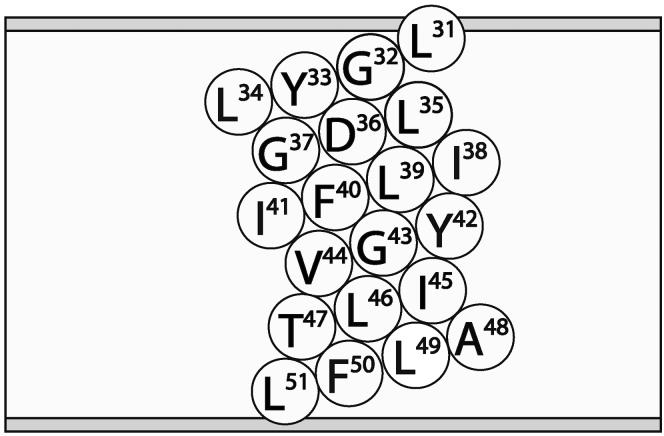
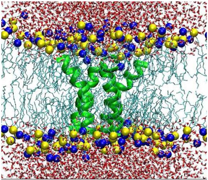
In this section we test our new map on the amide I modes of the trans-membrane domain of CD3-ζ. Each peptide chain is composed of 21 residues, Leu-31 to Leu-51, with an acetyl N-terminal cap (called residue Ace-30) and an NHCH3 group for a C-terminal cap; the sequence used in the MD simulations, along with its schematic representation in the membrane, is given in Fig. 1. The initial peptide structure used in the simulation was developed by Arkin and coworkers using site-specific IR dichroism.69 The system in the MD simulation (using GROMACS) includes a tetrameric CD3-ζ peptide bundle, a lipid bilayer consisting of 119 dimyristoylphosphocholine (DMPC) molecules, 3651 SPC water molecules and 4 sodium counterions. The extended version of the GROMOS87 force-field parameter set was used for the peptides, and those of Bergel and coworkers for the DMPC lipids.85 All bonds were constrained with the LINCS algorithm, the temperature was set to 310 K to sustain the stability of the lipid bilayers by implementing a Nosé-Hoover thermostat, and the Parrinello-Rahman pressure coupling at 1 bar was also employed. PME was used to deal with the long-range Coulomb interactions. The simulation length was 1 ns with a time step of 2 fs. A snapshot of the system is shown in Fig. 2; one sees that the CD3-ζ chains form an asymmetric (with respect to the central plane of the membrane) tetrameric bundle of peptide α-helices, in the lipid bilayer, all solvated by water. We note that the S13 parameterization was used in a previous simulation study of this system,20 but the electric fields were calculated incorrectly (and thus, for example, the magnitude of the calculated frequency shifts is significantly too large).
FIG. 1.
Schematic representation of the CD3-ζ peptide in the lipid bilayer.
FIG. 2.
Snapshot of the system from the MD simulation of CD3-ζ. The tetrameric CD3-ζ peptide bundle is represented by green ribbons. The tails of the lipid molecules are shown as light green lines while the yellow and blue spheres represent the N and P atoms in the head groups, respectively. Oxygen and hydrogen of water are in red and light gray, respectively.
A. Average frequency shifts
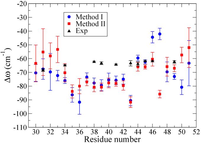
We adopted two methods to calculate the instantaneous local amide I frequencies for each residue. In Method I, the completely electrostatic approach, for each residue we calculated the electric fields on the amide C and N atoms from the water molecules as described above, and from the lipid molecules and counterions, and in addition for each (C or N) atom included the fields from peptide atoms that were more than three covalent bonds away (which is consistent with the 1-4 Coulomb exclusion in the GROMACS simulation).63 We then used Eq. (10) (the New/G96 map) to calculate the frequency. Thus in this approach one simply assumes that one can use the NMAD/D2O map without modification, and calculate the fields from all charged atoms outside the exclusion zone and inside the cutoff. Note that although the CD3-ζ simulation uses the extended GROMOS87 force field, the New/G96 parameterization is for the GROMOS96 force field. However, since the differences in these force fields are not great (for example both use SPC water), we do not expect this to cause major problems. The average frequency shifts from the gas-phase value of NMAD (1717 cm-1) are plotted for Ace-30 to Leu-51 (we refer to the amide I modes according to the residue containing the carbonyl bond) in Fig. 3, and labeled as Method I.
FIG. 3.
Frequency shifts from gas-phase values, Δω, versus residue number. Calculations using Methods I and II are described in the text. The numbers reported are the averages of the four helices in the CD3-ζ bundle; the (one-sigma) error bars indicate the standard deviations of the mean.
It is also possible that the electrostatic approach for calculating the frequency perturbation from at least some of the peptide atoms is not adequate (or that it is adequate, but with a different map). Alternatively, then, one can consider perturbations to a given amide I frequency due to nearest-neighbor residues through φ - ψ maps determined from quantum chemical calculations.52,65,66 In what follows we have adopted the approach of Jansen and coworkers52 and used their φ - ψ map to determine the contribution to the frequency perturbation from the backbone atoms of nearest-neighbor residues. In our implementation the frequency perturbation due to all other peptide atoms, including all atoms on side chains on the residue of interest and its nearest neighbors, and on non-nearest-neighbor residues, as well as that due to solvent (water or lipid) molecules and counterions, is given by the New/G96 map. Frequency shifts calculated with this approach are shown in Fig. 3 and labeled as Method II. One sees that in general the agreement between these two sets of frequency shifts is quite good.
In Fig. 3 we have also plotted the experimental frequency shifts obtained for the 11 13C=18O isotope-labeled residues.22 To obtain these results from the measured frequencies we subtract the gas-phase value of 1657.4 cm-1, which is the gas-phase value of normal NMAD corrected by the 13C=18O isotope shift of 59.6 cm-1.14,17,41 We note that the theoretical frequency shifts are in the correct range, and on average are quite close to the experimental shifts. On the other hand, the theoretical shifts show significantly more variation from residue to residue than do the experimental results. On the basis of this comparison between theory and experiment it is not possible to favor one of the calculational methods over the other.
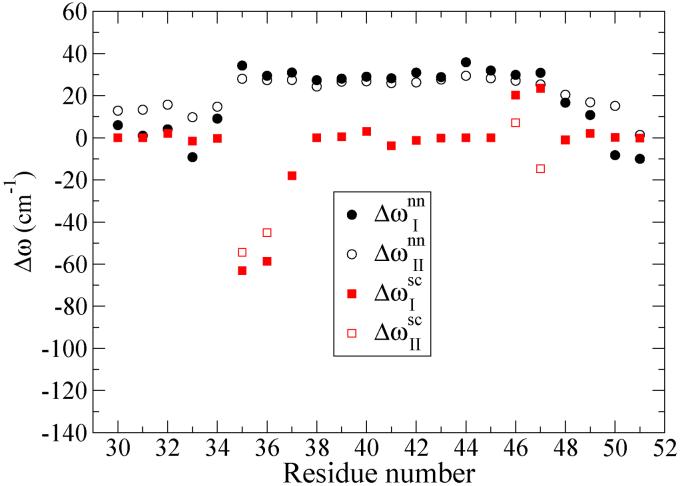
The differences in the frequency shift calculations for Methods I and II arise only from differences in perturbations from atoms on the residue of interest and its neighbors on either side. To reiterate, in Method I we simply used the NMAD/D2O map for all atoms on these three residues except those subject to the 1-4 exclusion mentioned above. We note that some of those excluded atoms are on side chains. In Method II the perturbations from the backbone atoms of the two neighboring residues are accounted for by the φ - ψ map, and all those on side chains by the NMAD/D2O map. Therefore some side-chain atoms give a contribution in Method II, but do not give one in Method I. In Fig. 4 we show the contributions to the frequency shift, as a function of residue, from nearest-neighbor backbone atoms (Δωnn), and from side-chain atoms of the three relevant residues (Δωsc), for Methods I and II. Considering first the nearest-neighbor contributions, one sees that from residue 35 to residue 47 the frequency shifts are positive, nearly uniform, and nearly the same for the two methods. They are uniform since the peptide is α-helical, with similar φ - ψ angles, in this region. The NMAD/D2O map does a surprisingly good job (compared to the presumably more accurate φ - ψ map) for these residues. Toward both ends of the peptide the frequency shift varies more (the helix is less rigid), becomes smaller, and the NMAD/D2O map performs less well. Turning next to the side-chain contribution, for most residues this contribution is small or zero, while for residues 35, 36, 46 and 47 the contributions are substantial. The largest difference between the two methods occurs for Thr-47, where for example its β-carbon makes contributions to the fields on both C and N atoms in Method II, but does not in Method I.
FIG. 4.
Contributions to frequency shifts for Methods I and II from atoms on the residues of interest, and those on its two nearest-neighbor residues, versus residue number. Δωnn denotes contributions from backbone atoms on nearest-neighbor residues, and Δωsc denotes contributions from side-chain atoms on all three residues.
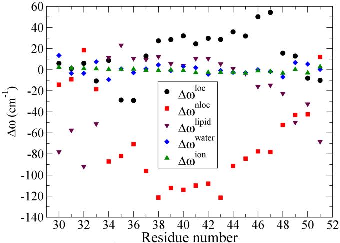
It is also of interest to decompose the frequency shifts into their different contributions, for each residue.20 We choose to consider the contributions from all (including side-chain) atoms on the residue of interest and its two nearest-neighbor residues (which is the sum of the two “local” peptide contributions discussed above, in this context labeled as Δωloc), from all other (non-local) peptide atoms (Δωnloc), from all lipid atoms (Δωlipid), from all water atoms (Δωwater), and from the counterions (Δωion). These five contributions for each residue, for Method I (the last four contributions are identical in the two methods), are shown in Fig. 5. In general the largest contributions come from Δωnloc, that is, from peptide atoms on residues that are at least next-nearest neighbors to the residue of interest. For residues 34 to 47 these are large and negative, coming from intra-helix hydrogen bonding. For residues on the ends, where one or both of these hydrogen bonds are broken, the shifts are less negative. The next largest contributions come from lipid atoms (in this case the positively and negatively charged amine and phosphate groups, respectively). For residues 30 to 33 and 49 to 51 (those in the head-group region) these contributions are large and negative, while for residues 34 to 48 (in the middle of the membrane), these contributions are much smaller. The third largest contributions in general come from nearby peptide atoms through Δωloc. As discussed above, for this contribution the greatest variation from residue to residue is due to the different side chains. The contribution from water is near zero (as expected) for residues in the middle of the membrane, but is still surprisingly small for residues near the membrane surfaces. The contributions from the counterions (there are only four of them) are very small, as expected.
FIG. 5.
Contributions to frequency shifts for Method I versus residue number, from: all (including side-chain) atoms not subject to the 1-4 exclusion on the residue of interest and its two nearest-neighbor residues (Δωloc), all other peptide atoms (Δωnloc), all lipid atoms (Δωlipid), all water atoms (Δωwater), and the four counterions (Δωion).
A few general comments about these results are also in order. First of all, each of these contributions varies widely from residue to residue. Thus, for example, the non-local peptide contribution varies from -120 to +20 cm-1, the local peptide contribution from -30 to +50 cm-1, and the lipid contribution from -90 to +20 cm-1. The overall frequency shift, obtained from the sum of the five contributions, varies much less (from -90 to -40 cm-1 for Method I), since, for example, from residue to residue one kind of red-shifting hydrogen bond (intra-helix) is replaced by another (lipid). Secondly, we must acknowledge that the (average) contribution from water molecules (from which the map was obtained) is very small indeed, meaning that most of the frequency perturbations come from atoms reflecting environments from which the map was not parameterized. This points out the very strong need for systematic studies of the accuracy of this map in these circumstances, and very likely for the development of better maps.
B. 2D-IR spectra
We also can compare theoretical and experimental results for the 2D-IR spectra for each of the labeled samples, all taken with the waiting time set to zero. Our calculations assume infinitely short pulses, in which case only the rephasing response is relevant, which is given by43,78,86
| (11) |
where ω21 is the transition frequency between the first and the second vibrational excited states, and T21 is the vibrational relaxation time from the second vibrational excited state to the first vibrational excited state. To obtain this expression one once again invokes the second-cumulant truncation, the Condon approximation, and also neglects orientational dynamics. In addition, it is assumed that the frequency gaps are strictly correlated (δω21 (t) = δω10 (t)) and that |μ21|2 = |μ10|2, where μ10 is the transition dipole between the ground state and the first vibrational excited state and μ21 is the transition dipole between the first and the second vibrational excited states.43,78 In the calculation of 2D-IR spectra for CD3-ζ, the experimental T10 of 600 fs and T21 of 400 fs are used for all residues.21,22 An anharmonic shift of 14 cm-1 is also taken from the experiments to calculate ⟨ω21⟩.22 The signal S123(ω1, 0, ω3) was calculated by double half-Fourier transforming the real part of the response function:78,86
| (12) |
The absolute value spectra were generated by plotting the magnitude of S123(ω1, 0, ω3) as a function of two frequency variables ω1 and ω3.22
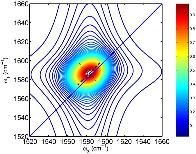
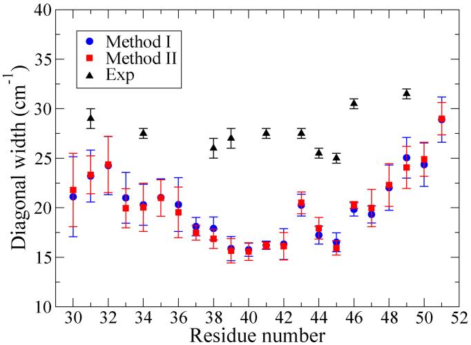
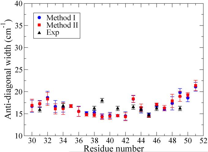
For example, shown in Fig. 6 is the 2D-IR spectrum for Leu-49 calculated using Method I. The shape of the theoretical 2D-IR spectrum compares reasonably well with the experimental results,21 although the former is too round. The diagonal and anti-diagonal widths for all residues using both Methods I and II are calculated and plotted in Figs. 7 and 8. As observed in the experiments, the calculated diagonal widths are more dependent on the residue position than are the anti-diagonal widths.22 As shown in Figs. 7 and 8, the theoretical results from Methods I and II share a very similar trend. While the theoretical anti-diagonal widths are in excellent agreement with experiment, the theoretical diagonal widths are systematically too small compared to experiment, although the asymmetric shape as one passes from one side of the membrane to the other is correctly captured by the theory. Moreover, the theoretical diagonal width for Gly-43 is somewhat enhanced, as in experiments, while similar enhancements for Leu-39 and Ile-41 are not observed theoretically.
FIG. 6.
2D-IR spectrum for Leu-49 calculated using Method I. The line shape shown is averaged over the four helices in the CD3-ζ bundle. The frequencies in the figure have been shifted by 59.6 cm-1 for a direct comparison with the experimental 13C=18O spectrum.21 The diagonal width (the dashed line is the FWHM) is calculated from a diagonal slice through the maximum; the anti-diagonal width (the dotted line is the FWHM) is calculated from an anti-diagonal slice through the maximum.
FIG. 7.
Diagonal widths in 2D-IR spectra; the error bars indicate the standard deviations of the mean.
FIG. 8.
Anti-diagonal widths in 2D-IR spectra; the error bars indicate the standard deviations of the mean.
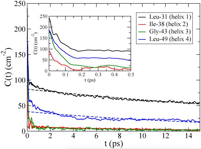
To understand further the factors that impact the diagonal widths we analyzed the FTCFs calculated using Method I for all the residues, among which four FTCFs are selectively plotted in Fig. 9. The FTCFs have different initial values, and in general show a fast drop, which is mostly over by about 200 fs, and a much slower decay. We thus approximated each FTCF by the form
| (13) |
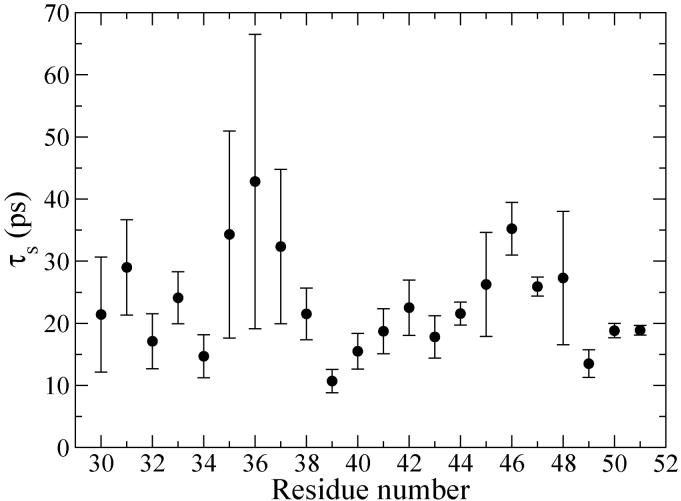
which involves a slow exponential decay, and an unspecified fast component. We first fit each FTCF starting at 500 fs to an exponential decay; such (reasonably good) fits are shown in Fig. 9. The τs thus obtained are in the range of tens of picoseconds, and are not tremendously sensitive to the residue position, as shown in Fig. 10. The fast component of the FTCF, Cf(t), is determined numerically by subtracting the slow exponential decay from C(t). If the fast component is in the homogeneous limit and the slow component is in the inhomogeneous limit, then the line shape function can be approximated by87
| (14) |
where
| (15) |
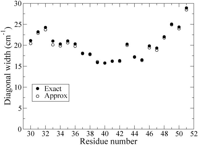
The diagonal widths of 2D-IR spectra calculated with the approximate g(t) (Eq. (14)) are plotted in Fig. 11 for all residues. The good agreement for 2D-IR diagonal widths using the exact and approximate g(t) verifies the validity of Eq. (14).
FIG. 9.
FTCFs for four residues in the CD3-ζ bundle calculated using Method I. The long-time exponential decays obtained from fitting data for t ≥ 500 fs are plotted as dashed lines.
FIG. 10.
Time constants for the slow decay, τs, obtained for each residue by fitting its FTCF for t ≥ 500 fs. The numbers reported are the averages of the four helices in the CD3-ζ bundle; the error bars indicate the standard deviations of the mean.
FIG. 11.
Diagonal 2D-IR widths using exact and approximate line-shape functions (see text).
The IR FWHM linewidth resulting from the first (homogeneous) term in Eq. (14) would be
| (16) |
while that from the second (inhomogeneous) term would be
| (17) |
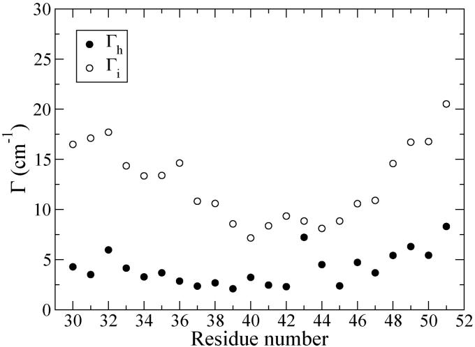
In Fig. 12 we show these two hypothetical linewidths for each residue. One sees that the inhomogeneous linewidths are roughly three times larger, and thus make the dominant contribution. It is also interesting that these inhomogeneous linewidths share a similar trend with the calculated 2D-IR diagonal widths (see Fig. 11). These two facts suggest that the 2D-IR diagonal widths mainly reflect the inhomogeneous frequency distributions, which in turn are due to the ensemble of local structures. Nearby the membrane surfaces, the lipid headgroups and water molecules partially unfold the ends of the peptides, resulting in larger structural disorder and thus broader inhomogeneous frequency distributions; in contrast, in the membrane interior the peptides are more constrained by the neutral environment, showing narrower frequency distributions. Moreover, since the peptide bundle shape (see Fig. 2) is asymmetric, being more expanded on the N-terminal end, the fall and rise of the diagonal linewidths as one goes from residues 31 to 51, and consequently passes through the membrane, is also asymmetric. In particular, the expanded N-terminal end is more immersed in the membrane, and thus has smaller frequency fluctuations, and smaller diagonal linewidths.
FIG. 12.
Homogeneous and inhomogeneous IR linewidths (see text).
In looking at the pattern of calculated diagonal linewidths, that of Gly-43 is anomalously large. From Fig. 12 one sees that in this case this is due to an unusually large homogeneous linewidth. In order to determine the source of this enhancement, we first noticed from the simulation that the carbonyl of Gly-43 participates in an extra intra-helical hydrogen bond with the side-chain hydroxyl of Thr-47. By artificially deleting the frequency perturbation from this hydroxyl, we find that the homogeneous linewidth of Gly-43 drops from 7.2 to 2.3 cm-1, while its inhomogeneous linewidth has a rather marginal change from 8.8 to 7.9 cm-1. Thus we conclude that the enhanced homogeneous linewidth is due to the additional fast dephasing from this extra fluctuating hydrogen bond. As noted above the enhancement of the diagonal linewidth for Gly-43 (compared to some other residues in the middle of the membrane) was also seen experimentally.22
V. CONCLUDING REMARKS
In this paper we report the development of a simple empirical amide I vibrational frequency map, which relates the amide I frequency to components of the electric fields on the relevant C and N atoms. The map is applied to the CD3-ζ trans-membrane peptide bundle system, and gives fair agreement for average frequencies and 2D-IR diagonal linewidths with experiments on a number of different isotope-edited samples. The calculated frequency shifts (from the gas-phase value) are in the same range as the experimental results, but show greater variation as a function of residue position than experiment. The calculated diagonal widths are all somewhat smaller than those in experiment, but on the whole demonstrate an asymmetric fall and rise, as one passes from one side of the membrane to the other, and as observed in the experiments. Theoretical analysis of the results shows that the diagonal widths are dominated by static frequency inhomogeneities, arising from a distribution of static structures. Thus there is more structural variation near the edges of the membrane, due to lipid headgroups and water penetration, than in the center of the membrane. The asymmetry in the pattern of diagonal linewidths follows from the asymmetry in the peptide bundle structure, being more expanded on N-terminal end.
While these theoretical results are very promising, there remain significant discrepancies between theory and experiment, and so it is important to try to sort out their sources. Certainly in simulations such as these, one should always suspect the accuracy of any one given force field. As such, it would be desirable to repeat these calculations for other force fields. Another important issue has to do with the relevant time scales for conformational fluctuations in such a complicated protein/lipid/water system. In principle one needs to run long enough to sample all conformational fluctuations in the real experimental ensemble, which in practice might necessitate simulations of ms or longer. In our ns simulations, for example, we calculate the frequency shift for each residue in the tetrameric CD3-ζ peptide bundle by averaging over the means from the four helices. The large standard deviations of the mean for the calculated frequency shifts indicate that the four helices are not equivalent in the MD simulation, even though presumably in experiment they are. Doubling the simulation time did not improve this inequivalence, and so it is suspected that we are simply missing important conformational fluctuations on longer time scales. This could account for the observed greater variability in average frequency as a function of residue in theory compared to experiment; in much longer simulation runs perhaps this variability would average out to some extent. In addition, the insuffcient sampling of the long-time inhomogeneous fluctuations may be responsible for the smaller calculated diagonal widths compared to experiment, while the theoretical anti-diagonal widths determined more by the short-time local fluctuations seem to have converged.
Another important issue has to do with the accuracy of the vibrational frequency map, and especially its transferability from NMAD/D2O to a trans-membrane peptide bundle in aqueous solution. To be confident in our approach, one really needs systematic studies of dilute NMA in other polar and non-polar solvents, to assess the transferability of the map developed for water to other kinds of environments. Next one would want to consider the transferability of the map to small peptides, to assess the best way to take into account the dependence of local frequencies on nearest-neighbor φ -ψ and side-chain degrees of freedom. Finally one would want to consider peptides with well-defined α-helix and β-sheet secondary structures, to assess the best way to take into account the dependence of the local frequencies on different kinds of intramolecular hydrogen bonds.
Despite these caveats, we stress again the promise of a combined experimental and theoretical approach for understanding complicated biological protein systems. Judicious isotope editing affords a significant and profound simplification (since it produces isolated vibrational chromophores), and 2D-IR experiments are ideal for measuring the resulting weak signals in congested frequency regions. Thus synthesis (of the isotope-labeled samples) and ultrafast vibrational spectroscopy, together with molecular dynamics simulations and relatively simple frequency maps, can help provide structural and dynamical information on complicated systems of substantial biological interest.
VI. ACKNOWLEDGMENTS
The authors are grateful for I. T. Arkin for providing the peptide structure for MD simulations, and thank J. R. Schmidt, D. B. Strasfeld, A. M. Woys, T. l. C. Jansen, and G. Stock for valuable help and discussions. The research was supported by the National Science Foundation, through grant nos. CHE-0750307 and CHE-0832584, and by the National Institutes of Health through grant no. AI064797.
Biographies
I. AUTHOR BIOGRAPHIES

A. Y.-S. Lin
Yu-Shan Lin received her B.S. degree in Chemistry from National Taiwan University in 2004, where she worked with Professor Pi-Tai Chou on characterizing the spectroscopic properties of a novel class of fluorescent metal-cation probes. She is currently a graduate student with Professor James L. Skinner at the University of Wisconsin - Madison. Her research focuses on understanding vibrational spectroscopy of condensed-phase systems using molecular dynamics simulations and electronic structure calculations.

B. J. M. Shorb
Justin M. Shorb is a graduate student jointly appointed under James Skinner and John Moore at the University of Wisconsin - Madison. He completed his B.A. in Mathematics and B.S. in Chemistry at Hope College in Holland, MI. He was instructor of math and chemistry at Sinte Gleska University in Mission, SD. His research focuses on the development of parallel algorithms for spectroscopic analysis of protein simulations. He also works in the development of web-enhanced teaching of quantum mechanics in General Chemistry classrooms.

C. P. Mukherjee
Prabuddha Mukherjee is currently a postdoctoral research associate in Prof. Dana D. Dlott's laboratory at the University of Illinois at Urbana-Champaign. In 2008, he received his Ph.D. degree from University of Wisconsin at Madison under the supervision of Prof. Martin Zanni. His doctoral thesis included the vibrational characterization of membrane proteins through isotope edited labeling and 2DIR spectroscopy on different amide bonds. Before that he completed his Masters degree in Physical Chemistry in 2002 from Indian Institute of Technology at Bombay, and his B.S degree in Chemistry from Jadavpur University in 2000.

D. M. T. Zanni
Martin Zanni is the Meloche-Bascom Associate Professor of Chemistry at the University of Wisconsin-Madison. He completed his Ph.D. at the University of California, Berkeley and his postdoctoral research at the University of Pennsylvania. His research interests are primarily in developing and applying multi-dimensional spectroscopies to chemical and biological structural kinetics.

E. J. L. Skinner
James L. Skinner received his Ph.D. from Harvard with Prof. Peter Wolynes in 1979, and then did postdoctoral work with Hans Andersen at Stanford. He is currently the Joseph O. Hirschfelder Professor of Chemistry and Director of the Theoretical Chemistry Institute at the University of Wisconsin. His research interests involve the structure, dynamics, relaxation, and spectroscopy of condensed phase systems.
References
- 1.Schrader B. Infrared and Raman Spectroscopy: Methods and Applications. VCH; Weinheim: 1995. [Google Scholar]
- 2.Gremlich H-U, Yan B. Infrared and Raman Spectroscopy of Biological Materials. Marcel Dekker; New York: 2001. [Google Scholar]
- 3.Stuart B. Infrared Spectroscopy: Fundamentals and Applications. Wiley; Chichester, West Sussex, England; Hoboken, NJ: 2004. [Google Scholar]
- 4.Mukamel S. Annu. Rev. Phys. Chem. 2000;51:691. doi: 10.1146/annurev.physchem.51.1.691. [DOI] [PubMed] [Google Scholar]
- 5.Hochstrasser RM. Proc. Natl. Acad. Sci. USA. 2007;104:14190. doi: 10.1073/pnas.0704079104. [DOI] [PMC free article] [PubMed] [Google Scholar]
- 6.Park S, Kwak K, Fayer MD. Laser Phys. Lett. 2007;4:704. [Google Scholar]
- 7.Cho M. Chem. Rev. 2008;108:1331. doi: 10.1021/cr078377b. [DOI] [PubMed] [Google Scholar]
- 8.Hamm P, Hochstrasser RM. Ultrafast Infrared and Raman Spectroscopy. Markel Dekker; New York: 2001. p. 273. [Google Scholar]
- 9.Hamm P, Lim M, DeGrado WF, Hochstrasser RM. Proc. Natl. Acad. Sci. USA. 1999;96:2036. doi: 10.1073/pnas.96.5.2036. [DOI] [PMC free article] [PubMed] [Google Scholar]
- 10.Asplund MC, Zanni MT, Hochstrasser RM. Proc. Natl. Acad. Sci. USA. 2000;97:8219. doi: 10.1073/pnas.140227997. [DOI] [PMC free article] [PubMed] [Google Scholar]
- 11.Woutersen S, Mu Y, Stock G, Hamm P. Proc. Natl. Acad. Sci. USA. 2001;98:11254. doi: 10.1073/pnas.201169498. [DOI] [PMC free article] [PubMed] [Google Scholar]
- 12.Zanni MT, Gnanakaran S, Stenger J, Hochstrasser RM. J. Phys. Chem. B. 2001;105:6520. [Google Scholar]
- 13.Bredenbeck J, Hamm P. J. Chem. Phys. 2003;119:1569. [Google Scholar]
- 14.Fang C, Wang J, Charnley AK, Barber-Armstrong W, Smith AB, Decatur SM, Hochstrasser RM. Chem. Phys. Lett. 2003;382:586. [Google Scholar]
- 15.Cheatum CM, Tokmakoff A, Knoester J. J. Chem. Phys. 2004;120:8201. doi: 10.1063/1.1689637. [DOI] [PubMed] [Google Scholar]
- 16.Demirdöven N, Cheatum CM, Chung HS, Khalil M, Knoester J, Tokmakoff A. J. Am. Chem. Soc. 2004;126:7981. doi: 10.1021/ja049811j. [DOI] [PubMed] [Google Scholar]
- 17.Fang C, Wang J, Kim YS, Charnley AK, Barber-Armstrong W, Smith AB, Decatur SM, Hochstrasser RM. J. Phys. Chem. B. 2004;108:10415. [Google Scholar]
- 18.Chung HS, Khalil M, Smith AW, Ganim Z, Tokmakoff A. Proc. Natl. Acad. Sci. USA. 2005;102:612. doi: 10.1073/pnas.0408646102. [DOI] [PMC free article] [PubMed] [Google Scholar]
- 19.Fang C, Senes A, Cristian L, DeGrado WF, Hochstrasser RM. Proc. Natl. Acad. Sci. USA. 2006;103:16740. doi: 10.1073/pnas.0608243103. [DOI] [PMC free article] [PubMed] [Google Scholar]
- 20.Mukherjee P, Kass I, Arkin IT, Zanni MT. J. Phys. Chem. B. 2006;110:24740. doi: 10.1021/jp0640530. [DOI] [PMC free article] [PubMed] [Google Scholar]
- 21.Mukherjee P, Krummel AT, Fulmer EC, Kass I, Arkin IT, Zanni MT. J. Chem. Phys. 2004;120:10215. doi: 10.1063/1.1718332. [DOI] [PubMed] [Google Scholar]
- 22.Mukherjee P, Kass I, Arkin I, Zanni MT. Proc. Natl. Acad. Sci. USA. 2006;103:3528. doi: 10.1073/pnas.0508833103. [DOI] [PMC free article] [PubMed] [Google Scholar]
- 23.Kolano C, Helbing J, Kozinski M, Sander W, Hamm P. Nature. 2006;444:469. doi: 10.1038/nature05352. [DOI] [PubMed] [Google Scholar]
- 24.Hauser K, Krejtschi C, Huang R, Wu L, Keiderling TA. J. Am. Chem. Soc. 2008;130:2984. doi: 10.1021/ja074215l. [DOI] [PubMed] [Google Scholar]
- 25.Setnička V, Huang R, Thomas CL, Etienne MA, Kubelka J, Hammer RP, Keiderling TA. J. Am. Chem. Soc. 2005;127:4992. doi: 10.1021/ja043007f. [DOI] [PubMed] [Google Scholar]
- 26.Maekawa H, Formaggio F, Toniolo C, Ge N-H. J. Am. Chem. Soc. 2008;130:6556. doi: 10.1021/ja8007165. [DOI] [PubMed] [Google Scholar]
- 27.Koziński M, Garrett-Roe S, Hamm P. J. Phys. Chem. B. 2008;112:7645. doi: 10.1021/jp8005734. [DOI] [PubMed] [Google Scholar]
- 28.Wang J, Zhuang W, Mukamel S, Hochstrasser R. J. Phys. Chem. B. 2008;112:5930. doi: 10.1021/jp075683k. [DOI] [PMC free article] [PubMed] [Google Scholar]
- 29.Strasfeld DB, Lin YL, Shim S-H, Zanni MT. J. Am. Chem. Soc. 2008;130:6698. doi: 10.1021/ja801483n. [DOI] [PMC free article] [PubMed] [Google Scholar]
- 30.Kim YS, Liu L, Axelsen PH, Hochstrasser RM. Proc. Natl. Acad. Sci. USA. 2008;105:7720. doi: 10.1073/pnas.0802993105. [DOI] [PMC free article] [PubMed] [Google Scholar]
- 31.Choi J, Hahn S, Cho M. Int. J. Quan. Chem. 2005;104:616. [Google Scholar]
- 32.Mukamel S, Abramavicius D. Chem. Rev. 2004;104:2073. doi: 10.1021/cr020681b. [DOI] [PubMed] [Google Scholar]
- 33.Byler DM, Susi H. Biopolymers. 1986;25:469. doi: 10.1002/bip.360250307. [DOI] [PubMed] [Google Scholar]
- 34.Jackson M, Haris PI, Chapman D. J. Molec. Struct. 1989;214:329. [Google Scholar]
- 35.Arrondo JLR, Muga A, Castresana J, Goni FM. Prog. Biophys. Molec. Biol. 1993;59:23. doi: 10.1016/0079-6107(93)90006-6. [DOI] [PubMed] [Google Scholar]
- 36.Surewicz WK, Mantsch HH, Chapman D. Biochemistry. 1993;32:389. doi: 10.1021/bi00053a001. [DOI] [PubMed] [Google Scholar]
- 37.Barth A, Zscherp C. Quart. Rev. Biophys. 2002;35:369. doi: 10.1017/s0033583502003815. [DOI] [PubMed] [Google Scholar]
- 38.Williams S, Causgrove TP, Gilmanshin R, Fang KS, Callender RH, Woodruff WH, Dyer RB. Biochemistry. 1996;35:691. doi: 10.1021/bi952217p. [DOI] [PubMed] [Google Scholar]
- 39.Huang C-Y, Klemke JW, Getahun Z, DeGrado WF, Gai F. J. Am. Chem. Soc. 2001;123:9235. doi: 10.1021/ja0158814. [DOI] [PubMed] [Google Scholar]
- 40.Wang T, Du D, Gai F. Chem. Phys. Lett. 2003;370:842. [Google Scholar]
- 41.Torres J, Adams PD, Arkin IT. J. Mol. Biol. 2000;300:677. doi: 10.1006/jmbi.2000.3885. [DOI] [PubMed] [Google Scholar]
- 42.Huang C-Y, Getahun Z, Wang T, DeGrado WF, Gai F. J. Am. Chem. Soc. 2001;123:12111. doi: 10.1021/ja016631q. [DOI] [PubMed] [Google Scholar]
- 43.Mukamel S. Principles of Nonlinear Optical Spectroscopy. Oxford; New York: 1995. [Google Scholar]
- 44.Ham S, Kim J-H, Lee H, Cho M. J. Chem. Phys. 2003;118:3491. [Google Scholar]
- 45.Kwac K, Cho M. J. Chem. Phys. 2003;119:2247. [Google Scholar]
- 46.Bouř P, Keiderling T. J. Chem. Phys. 2003;119:11253. [Google Scholar]
- 47.Schmidt JR, Corcelli SA, Skinner JL. J. Chem. Phys. 2004;121:8887. doi: 10.1063/1.1791632. [DOI] [PubMed] [Google Scholar]
- 48.Bouř P, Michalik D, Kapitan J. J. Chem. Phys. 2005;122:144501. doi: 10.1063/1.1877272. [DOI] [PubMed] [Google Scholar]
- 49.Watson TM, Hirst JD. Mol. Phys. 2005;103:1531. [Google Scholar]
- 50.Hayashi T, Zhuang W, Mukamel S. J. Phys. Chem. A. 2005;109:9747. doi: 10.1021/jp052324l. [DOI] [PubMed] [Google Scholar]
- 51.l. C. Jansen T, Knoester J. J. Chem. Phys. 2006;124:044502. doi: 10.1063/1.2148409. [DOI] [PubMed] [Google Scholar]
- 52.l. C. Jansen T, Dijkstra AG, Watson TM, Hirst JD, Knoester J. J. Chem. Phys. 2006;125:044312. doi: 10.1063/1.2218516. [DOI] [PubMed] [Google Scholar]
- 53.Ganim Z, Tokmakoff A. Biophys. J. 2006;91:2636. doi: 10.1529/biophysj.106.088070. [DOI] [PMC free article] [PubMed] [Google Scholar]
- 54.Gorbunov RD, Nguyen PH, Kobus M, Stock G. J. Chem. Phys. 2007;126:054509. doi: 10.1063/1.2431803. [DOI] [PubMed] [Google Scholar]
- 55.Auer B, Kumar R, Schmidt JR, Skinner JL. Proc. Natl. Acad. Sci. USA. 2007;104:14215. doi: 10.1073/pnas.0701482104. [DOI] [PMC free article] [PubMed] [Google Scholar]
- 56.Auer B, Skinner JL. J. Chem. Phys. 2008;128:224511. doi: 10.1063/1.2925258. [DOI] [PubMed] [Google Scholar]
- 57.Skinner JL, Auer BM, Lin Y-S. Adv. Chem. Phys. 2008;000:000. [Google Scholar]
- 58.Smith JD, Saykally RJ, Geissler PL. J. Am. Chem. Soc. 2007;129:13847. doi: 10.1021/ja071933z. [DOI] [PubMed] [Google Scholar]
- 59.DeCamp MF, DeFlores L, McCracken JM, Tokmakoff A, Kwac K, Cho M. J. Phys. Chem. B. 2005;109:11016. doi: 10.1021/jp050257p. [DOI] [PubMed] [Google Scholar]
- 60.Hahn S, Ham S, Cho M. J. Phys. Chem. B. 2005;109:11789. doi: 10.1021/jp050450j. [DOI] [PubMed] [Google Scholar]
- 61.Choi J-H, Hahn S, Cho M. Biopolymers. 2006;83:519. doi: 10.1002/bip.20583. [DOI] [PubMed] [Google Scholar]
- 62.Choi J-H, Lee H, Lee K-K, Hahn S, Cho M. J. Chem. Phys. 2007;126:045102. doi: 10.1063/1.2424711. [DOI] [PubMed] [Google Scholar]
- 63.Torii H. J. Phys. Chem. B. 2007;111:5434. doi: 10.1021/jp070301w. [DOI] [PubMed] [Google Scholar]
- 64.Yang S, Cho M. J. Phys. Chem. B. 2007;111:605. doi: 10.1021/jp0649091. [DOI] [PubMed] [Google Scholar]
- 65.Gorbunov RD, Kosov DS, Stock G. J. Chem. Phys. 2005;122:224904. doi: 10.1063/1.1898215. [DOI] [PubMed] [Google Scholar]
- 66.Gorbunov RD, Stock G. Chem. Phys. Lett. 2007;437:272. [Google Scholar]
- 67.Klausner RD, Lippincott-Schwartz J, Bonifacino JS. Ann. Rev. Cell Biol. 1990;6:403. doi: 10.1146/annurev.cb.06.110190.002155. [DOI] [PubMed] [Google Scholar]
- 68.Abbas AK, Lichtman AH, Pillai S. Cellular and Molecular Immunology. Saunders Elsevier; Philadelphia: 2007. [Google Scholar]
- 69.Torres J, Briggs JAG, Arkin IT. J. Mol. Biol. 2002;316:365. doi: 10.1006/jmbi.2001.5267. [DOI] [PubMed] [Google Scholar]
- 70.Torres J, Briggs JAG, Arkin IT. J. Mol. Biol. 2002;316:375. doi: 10.1006/jmbi.2001.5268. [DOI] [PubMed] [Google Scholar]
- 71.MacKerell AD, Bashford D, Bellott M, Dunbrack RL, Evanseck JD, Field MJ, Fischer S, Gao J, Guo H, Ha S, Joseph-McCarthy D, Kuchnir L, Kuczera K, Lau FTK, Mattos C, Michnick S, Ngo T, Nguyen DT, Prodhom B, Reiher WE, Roux B, Schlenkrich M, Smith JC, Stote R, Straub J, Watanabe M, Wirkiewicz-Kuczera J, Yin D, Karplus M. J. Phys. Chem. B. 1998;102:3586. doi: 10.1021/jp973084f. [DOI] [PubMed] [Google Scholar]
- 72.Mayne LC, Hudson B. J. Phys. Chem. 1991;95:2962. [Google Scholar]
- 73.van der Spoel D, Lindahl E, Hess B, van Buuren AR, Apol E, Meulenhoff PJ, Tieleman DP, Sijbers ALTM, Feenstra KA, van Drunen R, Berendsen HJC. Gromacs User Manual version 3.3. 2005. www.gromacs.org. [Google Scholar]
- 74.Bekker H, Berendsen HJC, Dijkstra EJ, Achterop S, van Drunen R, van der Spoel D, Sijbers A, Keegstra H, Reitsma B, Renardus MKR. In: Physics Computing 92. Groot RA, Nadrchal J, editors. World Scientific; Singapore: 1993. [Google Scholar]
- 75.Berendsen HJC, van der Spoel D, van Drunen R. Comp. Phys. Comm. 1995;91:43. [Google Scholar]
- 76.Lindahl E, Hess B, van der Spoel D. J. Mol. Mod. 2001;7:306. [Google Scholar]
- 77.van der Spoel D, Lindahl E, Hess B, Groenhof G, Mark AE, Berendsen HJC. J. Comp. Chem. 2005;26:1701. doi: 10.1002/jcc.20291. [DOI] [PubMed] [Google Scholar]
- 78.Schmidt JR, Corcelli SA, Skinner JL. J. Chem. Phys. 2005;123:044513. doi: 10.1063/1.1961472. [DOI] [PubMed] [Google Scholar]
- 79.Hamm P, Lim M, Hochstrasser RM. J. Phys. Chem. B. 1998;102:6123. [Google Scholar]
- 80.van Gunsteren WF, Billeter SR, Eising AA, Hünenberger PH, Krüger P, Mark AE, Scott WRP, Tironi IG. The GROMOS biomolecular simulation program package. Hochschuleverlag AG an der ETH Zürich; Zürich, Switzerland: 1996. [Google Scholar]
- 81.Scott WRP, Hünenberger PH, Tironi IG, Mark AE, Billeter SR, Fennen J, Torda AE, Huber T, Kruger P, van Gunsteren WF. J. Phys. Chem. A. 1999;103:3596. [Google Scholar]
- 82.Berendsen HJC, Postma JPM, van Gunsteren WF, Hermans J. In: Intermolecular Forces. Pullman B, editor. Reidel; Dordrecht: 1981. [Google Scholar]
- 83.Press WH, Flannery BP, Teukolsky SA, Vetterling WT. Numerical Recipes. Cambridge University Press; Cambridge: 1986. [Google Scholar]
- 84.Kwac K, Lee H, Cho M. J. Chem. Phys. 2004;120:1477. doi: 10.1063/1.1633549. [DOI] [PubMed] [Google Scholar]
- 85.Berger O, Edholm O, Jahnig F. Biophys. J. 1997;72:2002. doi: 10.1016/S0006-3495(97)78845-3. [DOI] [PMC free article] [PubMed] [Google Scholar]
- 86.Khalil M, Demirdöven N, Tokmakoff A. J. Phys. Chem. A. 2003;107:5258. [Google Scholar]
- 87.Schmidt JR, Sundlass N, Skinner JL. Chem. Phys. Lett. 2003;378:559. [Google Scholar]
- 88.Zanni MT, Asplund MC, Hochstrasser RM. J. Chem. Phys. 2001;114:4579. [Google Scholar]


