Abstract
Dual-energy (DE) imaging of the chest improves the conspicuity of subtle lung nodules through the removal of overlying anatomical noise. Recent work has shown double-shot DE imaging (i.e., successive acquisition of low- and high-energy projections) to provide detective quantum efficiency, spectral separation (and therefore contrast), and radiation dose superior to single-shot DE imaging configurations (e.g., with a CR cassette). However, the temporal separation between high-energy (HE) and low-energy (LE) image acquisition can result in motion artifacts in the DE images, reducing image quality and diminishing diagnostic performance. This has motivated the development of a deformable registration technique that aligns the HE image onto the LE image before DE decomposition. The algorithm reported here operates in multiple passes at progressively smaller scales and increasing resolution. The first pass addresses large-scale motion by means of mutual information optimization, while successive passes (2–4) correct misregistration at finer scales by means of normalized cross correlation. Evaluation of registration performance in 129 patients imaged using an experimental DE imaging prototype demonstrated a statistically significant improvement in image alignment. Specific to the cardiac region, the registration algorithm was found to outperform a simple cardiac-gating system designed to trigger both HE and LE exposures during diastole. Modulation transfer function (MTF) analysis reveals additional advantages in DE image quality in terms of noise reduction and edge enhancement. This algorithm could offer an important tool in enhancing DE image quality and potentially improving diagnostic performance.
Keywords: dual-energy imaging, flat-panel detector, image registration, deformable registration, multiscale registration, morphological pyramid, mutual information, normalized cross correlation
INTRODUCTION
Dual-energy (DE) imaging removes overlapping anatomical structures that might otherwise impede the detection and characterization of subtle lung nodules in a chest radiograph.1, 2 By acquiring two projections at different energies and selectively decomposing distinct tissue components, the “soft-tissue” image effectively removes bony anatomical noise (e.g., ribs and clavicles), thereby enhancing the sensitivity in the detection of subtle lung nodules. The “bone” image, on the other hand, can distinguish calcified structures, thus potentially improving specificity in the characterization of benign lesions. Other applications of DE imaging abound, including musculoskeletal imaging (e.g., differentiation of fractures from bony metastases), cardiac imaging (e.g., imaging of coronary calcium), and interventional procedures (e.g., stent visualization).
“Double-shot” DE imaging (in which low- and high-energy projections are acquired in successive exposures) has been shown to offer improved detective quantum efficiency,3 increased spectral separation (resulting in higher contrast), and lower radiation dose compared to a “single-shot” technique (in which the two projections are acquired simultaneously by means of a detector sandwich). However, an intrinsic challenge to double-shot DE imaging is the susceptibility to motion artifacts resulting from anatomical misregistration between exposures.
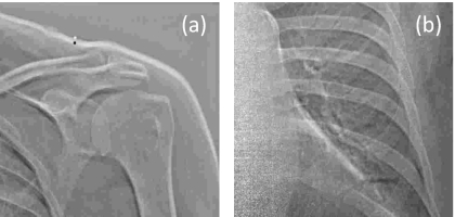
The time delay between two projections may range from hundreds of milliseconds4, 5, 6 to several seconds, depending on system configuration. Even small delays can result in appreciable motion artifacts in DE images—e.g., due to motion of the heart. Initial implementation of the experimental prototype DE imaging system used in this study has a fairly long interexposure delay of 5 to 8 s. For such a long delay, anatomical misregistation is unavoidable due to constant motion of the heart, respiratory motion (even during breath-hold—e.g., rebound of the diaphragm), and gross patient motion (e.g., patient relaxation, slouch, etc.). The resulting motion artifacts in DE images typically appear as bright or dark streaks delineating anatomical edges, reducing overall image quality and diminishing diagnostic performance. Example motion artifacts are illustrated in Fig. 1.
Figure 1.
Example motion artifacts in unregistered DE bone images. (a) Zoomed-in view of the shoulder. (b) Zoomed-in view in the region of the heart. The bright and dark edges result from anatomical misregistration between HE and LE exposures.
Rigid 2D-to-2D registration is not sufficient to achieve the necessary accuracy in image alignment at both global scales (e.g., shoulders and ribcage) and local scales (e.g., heart and vasculature). A variety of deformable 2D-to-2D registration algorithms have been proposed to register radiographs. To align chest radiographs acquired at separate times for the purpose of detecting interval change, Kano et al. developed an algorithm that computes cross correlation-based local matching of small regions of interest (ROIs) placed in the lung.7 The local displacements were applied using a nonlinear geometric warping technique. Ishida et al. added to this method an initial global matching found through cross correlation of two radiographs at low resolution8 and later extended the algorithm to include iterative steps.9 Armatoet al. employed the same algorithm in the subtraction of temporally sequential DE soft-tissue images.10 Other applications involve registering ventilation-perfusion images with digital chest radiography using contour detection and anatomical landmarks.11, 12 These techniques have demonstrated radiographic registration suitable for visualizing change over extended time scales (e.g., disease progression or treatment response). They were not developed for purposes of DE imaging, where the goal is subpixel level registration accuracy between LE and HE images acquired in rapid succession (within seconds).
For double-shot DE imaging, therefore, our goal was to develop a deformable 2D-to-2D registration algorithm that is fully automated (no manual intervention), computationally simple (and therefore fast by means of future multithreaded GPU implementations), robust against differences in pixel intensity between low-energy (LE) and high-energy (HE) projections (unlike, for example, Demons-type algorithms), and accurate in registering motion across both large (centimeter) and small (millimeter) anatomical scales. To address these challenges, a multiscale, multiresolution (MSMR) registration algorithm using a hybrid of mutual information (MI) optimization and normalized cross correlation (NCC) was developed to align HE and LE images prior to DE decomposition. Metrics of MI (Refs. 13, 14) and NCC (Ref. 15) are each commonly used similarity measures in 2D, 3D, and 4D as well as single- and multimodal image registration.16, 17, 18, 19, 20, 21 We evaluated the performance of both similarity measures and combined the two in a hybrid manner to optimize performance and speed. A multiscale (i.e., ROIs of various size considered in multiple passes) and multiresolution (i.e., variable pixel binning in each pass) approach proved to resolve misregistration across varying scales,16 avoid local minima,17 and improve computational efficiency.16, 17, 19, 22
METHODS
Description of algorithm
In the following section, we present an algorithm that operates on multiple scales and at multiple resolutions to transform the HE image in iterative passes. In each pass, a series of translation vectors is calculated by either MI or NCC optimization. A spatial transformation inferred from these vectors is then interpolated and applied to the HE image in a pixel-wise manner. The transformed HE image and original LE image constitute the inputs to the next pass, where the process is repeated. The rationale for the multiscale, multiresolution pyramid is described in Sec. 2A1, the choice of objective functions in Sec. 2A2, and image transformation and interpolation techniques in Sec. 2A3.
Multiscale, multiresolution morphological pyramid
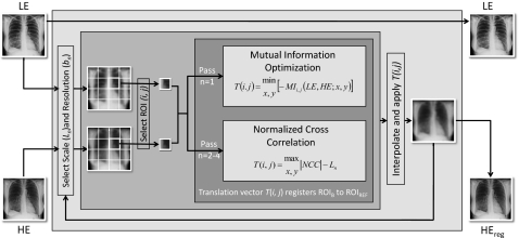
The algorithm operates by a morphological pyramid in which multiple iterations (passes) are performed at progressively smaller scale (i.e., size of ROI) and finer resolution (i.e., pixel size). The MSMR approach offers advantages (compared to a single-pass, full-resolution approach) in computational efficiency, avoidance of local minima, and correcting motion across various scales (discussed in Sec. 4A). The registration process is illustrated in Fig. 2. The LE image is taken as the fixed image (also called the target or reference image), and the HE image is the moving image (also called the source or transformed image). In theory, either image may be selected as fixed or moving, but taking the HE image as the latter offers an advantage to DE image quality, as discussed in Sec. 4D.
Figure 2.
Flowchart illustration of multiscale, multiresolution (MSMR) image registration.
In each pass (n), both images are divided into a number of ROIs of extent Ln. To allow transformations beyond the range of Ln, the ROIs in the HE image include an additional margin kn of approximately 1∕10 the size of Ln. Also in each pass, the pixel sizes of both the target and moving images are averaged over a given bin size (box mean over an area of sidelength denoted bn), resulting in an image of size 3000∕bn in which pixels are the average values from nonoverlapping bins. Both Ln and bn are in units of pixels in the original image. In a morphological pyramid, Ln and bn reduce or remain the same (but do not increase) at each pass. A number of potential “paths” (i.e., selection series of Ln, bn) were investigated as described in Appendix A, each presenting tradeoffs in the susceptibility to local minima and correction of small- or large-scale misregistration. The “diagonal” path provided the best overall performance and was used for all results below. For this nominal path, the original (3000×3000 pixel) images were registered in a total of n=4 passes. Nonoverlapping square ROIs of size Ln=720, 384, 192, and 96 were laid regularly in the middle of the image, leaving margins on the four sides to prevent transformations beyond the image in case “outward” translation vectors were calculated for the border ROIs. The respective pixel binning in each pass was bn=16, 8, 4, and 2 (i.e., pixel size 2.29, 1.14, 0.57, 0.29 mm in passes 1–4, respectively). As described in Appendixes A, B, a full-resolution pass (n=5; bn=1) was computationally intense and did not significantly improve registration performance.
Objective function—A hybrid approach
At each pass, ROIs are registered according to optimization of a given objective function—e.g., MI or NCC. The former is a prevalent metric for registration used in many applications16, 17, 18, 19, 20, 21 in combination with a given optimization technique (e.g., simplex search).23, 24 As discussed in Appendix C, registration based on MI and a simplex search was found to be fairly robust against local minima, although computationally slow. Registration by NCC, on the other hand, was fast, but may give poor performance for highly correlated images16 (i.e., exhibiting multiple peaks in the cross-correlation matrix). The two basic metrics are summarized below, motivating the implementation of a hybrid approach.
Mutual information optimization
Mutual information (MI) is defined as13, 14
| (1) |
where H(A) is the entropy of image A given by
| (2) |
Here, a represents pixel values in image A and pA(a) is the marginal probability distribution of image A. For two jointly distributed images A and B, the marginal probability distribution of A is simply its probability distribution disregarding information in B.
H(A,B) is the joint entropy of image A and B given by,
| (3) |
where pAB(a,b) is the joint probability distribution of image A and B which describes the probability that pairs of values (a,b) occur together. Misregistration results in dispersion of the joint probability distribution, which leads to higher joint entropy.21 Mutual information, presented as the difference between the entropies of A and B and their joint entropy, describes the shared information between two images.21, 25 Both pA and pAB were calculated with images normalized to 64 gray levels. Larger and smaller numbers of gray levels were investigated, with 64 selected as the smallest value for which registration performance was stable. The optimal alignment between two images is achieved when MI is maximized. Optima were computed using the MATLAB (vR2007a, The Mathworks, Natick, MA) function fminsearch, in which transformation vectors were varied until a maximum in MI (a minimum in −MI) was obtained. The search technique was based on the Nelder-Mead simplex algorithm23, 24 modified by imposing upper and lower bounds of the transformation vectors, thus constraining the search space of the x- and y-components within ±kn∕bn, where kn is the size of the additional margins included in ROIs of the HE image, and bn is the bin size, as defined in the previous section. Therefore, the ROI can be transformed within but not beyond the additional margin of size kn. This prevents unrealistic translations (e.g., caused by local minima or noisy regions with little anatomical features, e.g., the abdomen). The final transformation vector for the ROI is that which maximizes MI, represented as
| (4) |
where T(i,j) identifies the final transformation vector of the (i,j)th ROI of the moving image, MI is the mutual information between the (i,j)th ROI in the HE and LE images, and x and y are displacements in the horizontal and vertical directions, respectively.
Normalized cross correlation
The normalized cross correlation (NCC) matrix between ROIs in the HE and LE image was calculated as15, 16, 20
| (5) |
where and are the mean of the HE and LE images in the overlap region (x,y)∊Ω. Given HE and LE ROIs of size Ln+kn and Ln, respectively, NCC is the (2Ln+kn−1)2 cross-correlation matrix. Note that NCC is a matrix, not to be confused with Pearson’s correlation coefficient. NCC was calculated using the MATLAB function normxcorr2, with the position of the maximum value of the NCC matrix giving the displacement that maximizes correlation. Taking into account the relative sizes of the images, the translation vector for a given HE ROI is the difference between the location of the NCC peak and the size of the LE image ROI,
| (6) |
As described in Appendix C, both MI and NCC offered potential objective functions: the former was computationally slow but robust against local minima; the latter was considerably faster (by a factor of ∼6) but did not perform as well when the image data are are self-similar16—i.e., when subregions of an image can be approximated using other subregions of the same image. (Such self-similarity is more likely to occur in large ROIs, with the ribs offering a good example of a recurrent, self-similar pattern.) In the first pass (n=1) in particular, MI outperformed NCC. However, in passes n=2–4, the two performed equivalently. A hybrid approach was therefore implemented. In the first pass, MI constituted the objective function, where its resilience to local minima in the presence of large sets of anatomical features was essential, but computational efficiency was not a major limitation (since the images in pass n=1 involve few ROIs at large scale and coarse pixel size). In subsequent passes, registration was based upon NCC, where multiple peaks in the cross-correlation matrix were not as prevalent and susceptibility to local minima was not as severe (owing to smaller ROIs and good initial conditions provided by MI registration in pass 1). Computational efficiency was also essential in pass n=2–4 since the images involve many ROIs at small scale and fine pixel size.
Image transformation and interpolation
The set of translation vectors, T(i,j), computed for all ROIs in each pass are not directly applied. Instead, a local-weighted-mean transformation26 (LWM) was inferred from the pairs of control points related by the ensemble of vectors in a given pass. The LWM transformation was used to account for locally varying distortions, and was bilinearly interpolated to a pixel-wise transformation that is applied to the entire moving (HE) image. This in combination with multiple passes at multiple scales effects a deformable transformation.
Imaging system
As described in previous work,27, 28 an experimental prototype DE imaging system was developed based upon a Kodak RVG-5100 digital radiography chest stand (Carestream Health Inc., Rochester, NY). Modifications include: (1) a high-performance flat-panel detector (FPD) (3000×3000 pixels, 0.143 mm pixel pitch, CsI:Tl scintillator, Trixel Pixium-4600, Moirans, France); (2) a computer-controlled filter wheel for differential filter selection in low- and high-kVp projections; (3) a cardiac-gated image acquisition system; and (4) an acquisition workstation that controls imaging technique, filter selection, and synchronization of the source and FPD. A cardiac monitoring system was implemented for purposes of retrospective analysis of the gating system. The monitor recorded pulse oximetry and x-ray trigger signals to determine whether a given x-ray exposure was delivered synchronous to diastole or systole. Previous studies identified the optimal imaging techniques:29 an LE beam at 60 kVp and an HE beam at 120 kVp (0.6 mm Ag+2 mm Al added filtration), with the radiation dose allocated such that approximately 1∕3 of the total energy was imparted by the LE beam, and with total dose equivalent to that of a conventional PA chest radiograph (e.g., 0.11 mGy for average chest thickness).
Postprocessing of images, including offset-gain correction, deformable registration, and DE image decomposition was performed on a desktop PC (Dell Precision 380 workstation with a single-core 3.0 GHz GPU, 2 GB RAM). Initial implementation of the algorithm was in MATLAB, which, although known to be considerably slower than lower-level executable code (e.g., C++, C#, etc.), provided a suitable prototyping platform. Image review was performed on dual-head (1536×2048 pixels), 8-bit gray-scale displays (AXIS III, National Display Systems, Morgan Hill, CA).
Performance evaluation in patient images
Clinical imaging trial
Image data were collected from a preclinical patient imaging trial conducted at the University Health Network (Toronto, ON). The trial consisted of 220 patients accrued under informed consent. Exclusion criteria for the study included diseases that would result in cardiac arrhythmia, inability to maintain a breath-hold for ∼10 s, and anterior-posterior chest thickness exceeding 28 cm.28, 29 Patients were randomized to 5 arms varying in imaging technique, use of the cardiac trigger, etc., among which 129 DE images were acquired at optimal acquisition technique (kVplow, kVphigh, filter selection, dose allocation, and cardiac-gated) as indicated by previous work.29 The 129 images from the optimal technique group were used in the evaluation of registration performance below (Sec. 3A). An additional 21 DE images were acquired without cardiac gating but with otherwise optimal techniques, and were used in the evaluation of the cardiac-gating system in combination with the optimal technique group (Sec. 3B).
Deformable registration vs prospective cardiac gating
Cardiac motion presents a significant source of misregistration in DE imaging. This is certainly a concern for the prototype described above, for which low-and high-energy exposures are obtained on separate heartbeats. Similarly, this is a concern even for considerably faster DE imaging systems (e.g., 200,6 150,30 or 35 ms (Ref. 31) exposure interval), since chance exposure during systole can still present significant motion artifacts. The cardiac-gating system mentioned above aimed to deliver both exposures coincident with diastole through the use of a pulse oximeter and a model for heart-rate-dependent timing.28, 32 The timing model, designed to trigger at mid-diastole, accounts for the dependence of diastolic period on heart rate by a variable implemented delay that could support triggering at heart rates up to 140 bpm. As currently implemented, x-ray exposure was synchronous to mid-diastole of the same heartbeat as the oximeter trigger for heart rate ⩽65 bpm, and to mid-diastole in the subsequent heartbeat for heart rate >65 bpm. The simple oximeter-based gating system has been shown to provide significant reduction in cardiac motion artifact.32 In the current article, we evaluated the extent to which deformable image registration further mitigates cardiac motion artifacts or outperforms prospective gating altogether.
Of the 150 cases, 137 had timing information available for retrospective analysis. There were 109 cases involving both low- and high-energy exposures delivered synchronous to diastole (as determined by the cardiac monitoring system described in Sec. 2B). The remaining 28 cases involved one or both exposures acquired during systole. The quality of registration was evaluated in an image subregion about the heart as shown in Fig. 3 for the following cases:
-
(i)
[Systole trigger∕no registration]—unsuccessful cardiac gating, without image registration (hypothesized as the worst case), average heart rate=(78.3±10.8) bpm;
-
(ii)
[Diastole trigger∕no registration]—successful cardiac gating, without image registration (corresponding to a “hardware-only” approach); average heart rate=(77.5±15.2) bpm;
-
(iii)
[Systole trigger∕MSMR registration]—unsuccessful cardiac gating, with image registration (examining the extent to which image registration can overcome the hypothetical worst case), average heart rate=(78.3±10.8) bpm;
-
(iv)
[Diastole trigger∕MSMR registration]—successful cardiac gating with image registration (hypothesized as the best case), average heart rate=(77.5±15.2) bpm.The cases were further pooled to examine:
-
(v)
[(Systole or diastole) trigger∕no registration]—evaluating the degree of artifact to be expected in a population of ungated DE images without registration, average heart rate=(77.7±14.4) bpm; and
-
(vi)
[(Systole or diastole) trigger∕MSMR registration]—a “software-only” approach in which a population of ungated DE images is operated upon by MSMR registration, average heart rate=(77.7±14.4) bpm.
Figure 3.
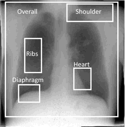
Example image illustrating the location of five subregions for registration performance evaluation—the overall image (excluding the collimators) and four anatomical subregions chosen to more closely examine gross patient motion, slouch, cardiac motion, and respiratory motion.
We hypothesized that (i) and (iv) would present worst and best cases, respectively, in terms of artifact magnitude. Further, we quantified the extent to which worst case motion (iii) could be resolved by deformable registration compared to best case motion—e.g., comparing data from (iii) to (ii). Finally, we compared the performance of a software-only approach [i.e., cases from (iii) or (vi) triggered in systole or diastole with MSMR registration applied] to a hardware-only approach [i.e., cases from (ii) involving successful diastole gating, but no registration algorithm].
Performance evaluation
Registration performance was quantified in terms of the absolute value of MI [i.e., ∣MI∣ as in Eq. 1] between the moving (HE) image and the fixed (LE) image. Higher ∣MI∣ corresponds to better image registration performance. Results were computed as the average ∣MI∣ over all cases within a particular group, with error bars reflecting 2 standard deviations. Recognizing that adopting a figure of merit (∣MI∣) that is also an objective function in the registration algorithm (MI in the first pass of the hybrid algorithm) creates a potential for bias in the evaluation, we evaluated other performance metrics as well—e.g., sum of squared differences, correlation coefficient and coefficient of variation in difference histograms. Each followed the same trends as ∣MI∣, and ∣MI∣ appeared to best reflect qualitative changes in image quality; therefore, ∣MI∣ is used throughout.
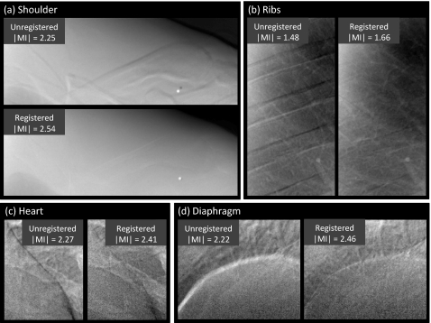
Registration performance was evaluated considering the overall image as well as the four subregions illustrated in Fig. 3. The overall image region (2700×2700 pixels) contained nearly the entire field of view, excluding collimator edges. The shoulder subregion (1100×400 pixels) included the left clavicle, the first and second ribs, and part of the left lung apex. The ribs subregion (400×800 pixels) typically contained the fifth to the eighth ribs, comprising the majority of the right lung but excluding the vasculature adjacent to the mediastinum. The heart subregion (400×500 pixels) and diaphragm subregion (500×400 pixels) were selected to evaluate cardiac and respiratory motion artifacts, respectively. The size of the overall image and subregions was fixed for all patients while the locations were manually selected for each case.
A Student t-test was used to evaluate the statistical significance of the difference measured in ∣MI∣ between two image groups. A one-sided t-test was used when testing for a directional alternative hypothesis (e.g., registered vs unregistered, as in Secs. 3A, 3B), whereas a two-sided t-test was used for nondirectional alternative hypothesis (e.g., hybrid algorithm vs MI optimization-only algorithm, as in Appendix C). For two groups comparing registration in the same patients (Sec. 3A and Appendix C), a pairwise t-test was used. Otherwise, a two-sample heteroscedatic (unequal variance) test was used (Sec. 3B). The t-test analysis was computed in MICROSOFT EXCEL.
As a basis of comparison and aid to interpreting the ∣MI∣ results, the approximate upper limit of ∣MI∣ was measured using an anthropomorphic chest phantom (model 55-8PL, Radiology Support Services, Long Beach, CA) imaged at the same techniques as in the patient imaging study. The ∣MI∣ of the resulting HE and LE images was calculated, illustrating the ideal case in which the patient was perfectly still between exposures, recognizing the potential variation associated with differences in attenuation (pixel values) of materials in the phantom and individual patients.
Effect of MSMR registration on spatial resolution
Measurements of the modulation transfer function (MTF) were performed to determine the transfer function of the registration algorithm and its effect on spatial resolution in the resulting DE images. The edge-spread measurement method has been described in previous work.33 A Pb edge (2 mm thick) was placed at a slight angle (∼5°) to the FPD matrix and imaged at the same LE and HE techniques as described above. In addition, three HE images were acquired in which the edge was manually perturbed from its original position: slightly (∼1 mm orthogonal to the edge), modestly (∼5 mm orthogonal to the edge), and grossly (∼10 mm orthogonal to and angulated with respect to the edge). The MTF was analyzed from the LE image, the HE image, and the three registered HE images. In each case, the MTF was computed by determining the oversampled edge spread function (ESF),34 the derivative of which yielded the line spread function (LSF). The absolute value of the fast Fourier transform (FFT) of the area-normalized LSF yielded the MTF. The MTF was reported as the average analyzed over 25 measurements performed at different regions along the edge. Considering the MSMR algorithm as a linear image transfer process, the MTF of the MSMR algorithm was estimated as the quotient of the MTF for a registered image divided by that of the original (unperturbed) image.
RESULTS
Registration performance
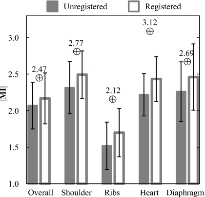
Figure 4 shows ∣MI∣ before and after registration averaged over 129 patients for the overall image and the four anatomical subregions. ∣MI∣ is significantly improved following MSMR registration in all cases (p<0.001). Although the increase in the population mean ∣MI∣ is fairly small, the small p-values (computed from pairwise, one-tailed t-tests) demonstrate a statistically significant improvement case by case. Of the 129 cases, there were only four in which registration degraded the overall ∣MI∣. As a basis of comparison, the ∣MI∣ values achieved with the stationary anthropomorphic chest phantom were 2.47 (overall), 2.77 (shoulder), 2.12 (ribs), 3.12 (heart), and 2.69 (diaphragm).
Figure 4.
Registration performance evaluated in terms of ∣MI∣ for registered and unregistered images. In each case (overall image as well as various subregions), the algorithm gave statistically significant improvement (p-value <0.001) in registration of the HE (moving) image with the LE (fixed) image. Values represented by the ⊕ symbol represent those obtained with the stationary anthropomorphic chest phantom.
Representative cases comparing the overall images and subregions before and after registration are shown in Figs. 56, respectively. The example images exhibit ∣MI∣ as close as possible (within 0.05) to the mean values plotted in Fig. 4 (and are therefore representative of average performance). Figure 5 illustrates the improvement in overall image alignment. The motion artifacts, most markedly around the patient’s left ribcage and shoulder, are corrected in the registered image, leading to significant improvement in DE image quality in both soft-tissue and bone images. Figure 6a illustrates the shoulder region and reveals significant reduction in bone edge artifacts about the clavicles arising from gross patient motion∕slouch. Note also the improved alignment of a lead BB placed on the patient’s back. Similarly, the soft-tissue images in Fig. 6b show the reduction of rib edges, improving the conspicuity of underlying bronchial structures. The bone image in Fig. 6c represents the typical magnitude of cardiac motion artifact—a dark (or bright) streak along the left ventricular wall that is significantly reduced following deformable registration. Finally, the bone image in Fig. 6d illustrates improvement in the respiratory motion artifact along the dome of the diaphragm, which can undergo significant motion (relaxation) even under conditions of breath-hold.
Figure 5.
Example images before and after MSMR registration: (a) soft-tissue images and (b) bone images. Representative cases were selected with ∣MI∣ close to the population mean in Fig. 4.
Figure 6.
Example DE images in the subregions of Fig. 3 before and after MSMR registration. Representative cases were selected with ∣MI∣ close to the population mean in Fig. 4. Subregions represent (a) shoulder, (b) ribs, (c) heart, and (d) diaphragm.
Deformable registration vs prospective cardiac gating
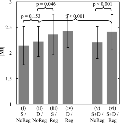
The mean ∣MI∣ of the heart subregion with and without registration is plotted in Fig. 7 for diastole trigger (N=109 cases), systole trigger (N=28 cases), and pooled (diastole and systole, N=137 cases) groups. The registration algorithm is seen to improve image alignment in all groups. As expected for cases without registration, diastole trigger (group ii) improved ∣MI∣ compared to systole trigger (group i), although to a fairly small extent (, , p-value=0.153), since the simple hardware gating system allows exposure to trigger anywhere within the diastolic phase (i.e., does not provide a trigger at precise subphases as might be achieved with ECG). Also as expected, cases with diastole trigger and MSMR registration (group iv) exhibit the best performance. Comparing group (iii) with group (ii), the results demonstrate that the algorithm alone improves registration even in the worst case (systole trigger) to a greater degree than the best case (diastole trigger) achievable by the hardware gating system alone. Thus, the software approach performs better (in the worst case) than the hardware approach (in the best case) (p-value=0.046). Finally, the pooled cases (groups v and vi) demonstrate that, in a population of systole or diastole trigger images (analogous to ungated acquisition), the algorithm imparts a significant improvement in image alignment (p-value<0.001) and gives registration superior to that of the hardware gating system alone (group ii) (p-value<0.001).
Figure 7.
Registration performance associated with a cardiac-gating system in comparison to and in combination with the MSMR registration algorithm. The algorithm is found to improve registration beyond that achievable with a simple gating system—even in the case of systole trigger. Abbreviations: S–systole trigger group; D–diastole trigger group; S+D–pooling of systole and diastole trigger groups; Reg–with registration; NoReg–without registration.
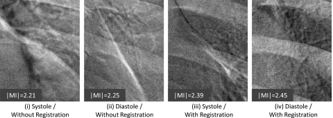
Example images of the heart subregion are shown in Fig. 8. Representative images are those with ∣MI∣ close to the population mean in Fig. 7. As evident in the bright streak artifact along the border of the heart, the images are qualitatively consistent with Fig. 7: worst performance for systole trigger without registration (group i); improved performance with diastole trigger (group ii); further improvement via registration—even for systole trigger (group iii); and best overall performance for diastole trigger and registration (group iv).
Figure 8.
Example images in the heart subregion corresponding to systole and diastole triggers with and without MSMR registration. Representative cases were selected with ∣MI∣ close to the population mean in Fig. 7.
Effect on spatial resolution
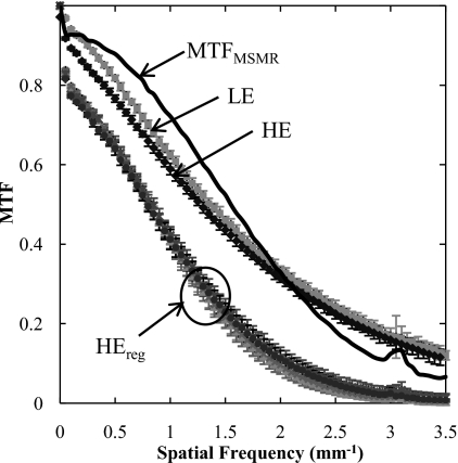
MTF results are summarized in Fig. 9. The MTF of the LE and HE are approximately the same. For each of the perturbed HE images, the registered image exhibits MTF that is reduced from that of the original (unperturbed) image as a result of bilinear interpolation during image transformation. The change in MTF for HEreg is approximately independent of the degree of perturbation (slight, modest, or gross). The MTF for the registration algorithm (given by the quotient of the mean registered MTF and the original MTF) is also shown, suggesting a low-pass characteristic comparable to that of the detector MTF. The small jump in the MTF at 3.1 mm−1 is believed to be associated with the registration algorithm (likely due to “spurious” response of the bilinear interpolation filter35 applied in the image transformation). The algorithm therefore imparts a characteristic blurring of the transformed image. Note, however, that blurring of one image in DE image decomposition is analogous to an unsharp mask, imparting edge enhancement and an improvement in the MTF of the resulting DE image. Also, as discussed below, blurring of the HE image as a result of registration is analogous to a noise-reduction technique30 in which the HE image is purposely blurred to reduce image noise.
Figure 9.
MTF measurements based on LE, HE, and registered HE (HEreg). The transfer function of the registration algorithm is labeled MTFMSMR, calculated as the quotient of MTFs for the registered (HEreg) and unregistered (HE) cases.
DISCUSSION AND CONCLUSIONS
An algorithm for registering two x-ray projections acquired during DE imaging of the chest has been described and characterized. The algorithm combines MI optimization and NCC in multiple passes in which the HE image is registered at progressively smaller scales and higher resolutions. Evaluation of registration performance in a cohort of 129 patients imaged at optimal DE techniques demonstrated a statistically significant improvement in image alignment. For the heart subregion in particular, registration outperformed a simple cardiac-gating system that triggers both projections within the diastolic phase of the heart cycle. The blurring effect of registration on the HE image appears to offer an additional advantage in DE image quality in terms of edge enhancement and reduced noise analogous to common noise reduction techniques.36
An intrinsic limitation to DE image registration and the work reported above lies in the fact that 2D transformations cannot accurately describe 3D motion,37 thus making 2D projection registration an estimate of the true 3D transformation. Also, as identified in other work,16, 21, 25 the inherent limitations of MI and NCC as similarity measures might deteriorate registration performance. Investigation of the relevance of these limitations in the context of DE image registration will be subjects of future research.
Multiscale hybrid registration
An algorithm operating on multiple scales and resolutions is seen to address the variable scales and types of motion in different regions of the chest. Gross patient motion, e.g., shift and slouch, exhibited most remarkably by large anatomical structures such as the ribcage, clavicles, and skin lines, generally requires large scales and lower spatial resolution to register. Motion on a finer scale, e.g., cardiac and diaphragm motion, requires deformation over a smaller scale and higher resolution. Even finer motion of vasculature and bronchioles requires a further decrease in scale and an increase in resolution to correct. Therefore, an inverse relationship exists between the scale (i.e., spatial extent) over which deformations are computed and the spatial resolution (i.e., pixel size) within the image at each iteration. By reducing or retaining Ln and bn in each pass, the algorithm corrects large-scale features first and then addresses motions on finer levels. Numerous registration paths could be considered (i.e., combinations of Ln and bn as in Appendix A), but the diagonal path with sequential halving of scale and doubling of spatial resolution (i.e., the “diagonal” path in Fig. 10) proved to be the best choice in terms of registration performance. The MSMR approach offers additional advantages in the optimization process in computational efficiency (by reducing the search space and speeding convergence) and avoidance of local minima.
The multiscale algorithm also combines MI optimization and NCC in a hybrid manner. As discussed in Appendix C, MI effectively corrected large-scale motion and was robust against local minima. Due to the small number of ROIs in pass 1, MI optimization did not constitute a computational burden. In passes 2–4, NCC gave a good performance in correcting motions on a finer scale and significantly improved computational efficiency. The hybrid method performed equivalently to (nonhybrid) MI optimization alone and gave considerable improvement in speed (by a factor of ∼6).
Deformable registration vs prospective cardiac gating
The experimental prototype DE imaging system has a relatively long interexposure delay of 5–8 s, which will be improved in future implementations incorporating a faster FPD. Other double-shot DE imaging systems achieve delays as short as 200 ms (XQ∕I Revolution, General Electric, Milwaukee, WI). However, the problem of motion artifacts in double-shot DE imaging systems can persist even with subsecond delays. Patient drift and respiratory motion may be minimized by acquisition in rapid succession and breath-hold respectively, but cardiac motion remains a challenging source of misregistration.
Cardiac-gating systems have been shown to reduce cardiac artifacts in other DE imaging systems30, 38 as well as in the current prototype32 as assessed by human observers. This is consistent with the higher ∣MI∣ achieved by the diastole trigger group compared to the systole trigger group in Sec. 3B. Although the ∣MI∣ measurements exhibited a fairly large p-value for these two groups, this is likely due to the small size of the systole trigger group as well as evaluation of ∣MI∣ over the entire subregion (rather than just the cardiac edge). Software registration, even in the worst case (i.e., group iii, systole trigger, registered), was found to outperform successfully hardware-triggered cases (i.e., group ii, diastole trigger, unregistered). The pooled data (group vi) give a conservative estimate of how the software-only approach performs in an ungated population of images, indicating superior image alignment compared to that achievable by the hardware gating system alone (group ii). We note that the pooled data comprise fewer systole cases than an ungated group. It should also be recognized that other means of cardiac gating (e.g., ECG) can potentially mitigate motion artifacts to a greater extent compared to the diastole trigger in this study by distinguishing subphases within diastole. For example, the ECG-gated DE system by Sabol et al. differentiated R-R wave interval (100%) into 5% steps and could trigger within the desired phase with 2% error.30 Even with such accurate triggering, there is potential for artifacts resulting from cardiac, respiratory, or gross patient motion, and it is likely that the combination of accurate hardware cardiac gating and high-performance software registration would represent the best possible case.
Effect of registration on DE image quality
The interpolation process during registration is analogous to a simple smoothing filter applied to the HE image. This has two implications. First, noise in the HE image is reduced, thereby reducing noise in the DE soft-tissue and bone images. Second, blurring of the HE image has the effect of an unsharp mask, which results in edge enhancement in the DE soft-tissue and bone images. (As with noise reduction algorithms, such edge enhancement can be beneficial with respect to structures of interest but may also introduce edge artifacts.)
Future work
The registration algorithm reported and evaluated here in the context of DE imaging could provide a generic means of registering 2D images in single-modality and multimodality imaging applications. To the extent that MI does not assume a functional form or relationship between image intensities, the approach is compatible with the registration of images exhibiting different pixel intensities for common structures. The HE and LE projections forming the basis of the current study were acquired in fairly rapid succession (5–8 s) and exhibit a modest (though certainly appreciable) degree of motion (∼1–10 mm). Future studies will involve the evaluation of the registration algorithm on images with smaller as well as more severe motion artifacts, for example, faster acquisition DE images in which cardiac motion is the primary (or only) source of misregistration,6 and images acquired over much longer time scales with correspondingly more severe motion, as in temporal subtraction images acquired at an average of 13 month intervals.10 The hybrid MSMR algorithm will also be compared to other well-known registration techniques, such as B-spline. The clinical significance of registration in DE imaging is currently being evaluated in human observer tests of diagnostic performance.
ACKNOWLEDGMENTS
The authors would like to thank N. A. Shkumat for assistance with the experimental DE imaging prototype and cardiac-gating system, as well as Dr. K. Brock and S. Nithiananthan for advice in the development of deformable registration methods. Thanks also to Dr. A. C. Dhanantwari (Ontario Cancer Institute, Princess Margaret Hospital) for early implementation of the algorithm. This research was conducted in collaboration with Carestream Health Inc. (Rochester, NY) and was supported in part by the National Institutes of Health (Grant R01-CA112163-02).
APPENDIX A: SELECTION OF PATH
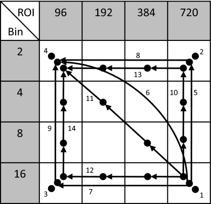
Figure 10 illustrates a variety of “morphological pyramids.” Four values of ROI size (Ln) and pixel binning factor (bn) were selected to divide the original image size (3000×3000 pixels) with a margin into square ROIs, each approximately half the size of the last. A given combination of ROI and bin size represents a point on a registration “path,” where the path can consist of single or multiple points. For multipoint paths, the “pyramid” aspect of a morphological pyramid suggests that the path climbs from larger ROI to smaller ROI and from larger bin size to smaller bin size, as represented in Fig. 10 by arrows that only point up and∕or left. Thus, each step in the morphological pyramid represents a smaller Ln and∕or a smaller bn.
Figure 10.
Morphological pyramid combinations of ROI sizes (Ln) and bin sizes (bn). A total of 14 possible registration paths was considered, including: single-point paths (#1–4), two-point paths (#5–9), and four-point paths (#10–14).
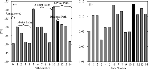
To examine the effect of Ln and bn on registration performance, nine patients exhibiting varying degrees of motion were investigated. The ∣MI∣ of unregistered images and images registered with the 14 different paths in Fig. 10 were computed. Example results for two patients are summarized in Fig. 11, with (a) corresponding to a case with large motion artifacts and (b) representing a case with slight misregistration.
Figure 11.
Registration performance of the 14 registration paths shown in Fig. 10 compared to unregistered images (path 0). (a) Performance in the presence of large motion artifacts (judged “large” by qualitative assessment of slouch, respiratory motion, and∕or cardiac motion artifacts in the unregistered DE images). (b) Performance in the presence of slight motion artifacts (also assessed qualitatively). The diagonal path (#11, marked in black) generally yielded the most robust performance regardless of motion severity.
The path yielding the best ∣MI∣ is seen to vary from case to case. For images exhibiting large motion artifacts, there is a strong dependence of registration performance on Ln. Registration paths consisting of only small ROI size (Ln=96, paths 3, 4, 9, and 14) perform poorly, whereas paths with at least one large ROI (Ln=720) significantly enhance the registration performance. For images with slight motion artifacts, there is no clear dependence of performance on Ln or bn, but paths traversing different Ln and bn appear to perform best overall. It is also interesting to note the marked performance difference demonstrated by paths 5, 10, and 14 for large and small motions, which suggests a possible direct relationship between the degree of motion artifact and Ln required for registration. The diagonal path (#11, marked in black) was found to provide high performance (within −0.02 of the highest ∣MI∣ in eight out of the nine cases) regardless of the severity of motion artifacts, and thus was the nominal choice applied to the entire patient cohort.
APPENDIX B. CONVERGENCE OF ALGORITHM
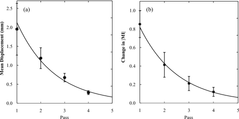
To determine the number of passes required for registration, the behavior of the algorithm was analyzed in terms of the mean ROI displacement (i.e., the amount of transformation applied to the image) and increment in ∣MI∣ (i.e., the improvement in image alignment) in each pass. The two quantities were computed as an average over all ROIs within a particular pass. Figure 12 shows the average results over a total of 129 patients, with error bars reflecting 2 standard deviations. Exponential fits are superimposed to extrapolate the curves to pass 5.
Figure 12.
(a) Mean ROI displacement in each pass. (b) Change in ∣MI∣ in each pass, calculated as the difference in ∣MI∣ between the current pass and the previous one (pass 1 with unregistered image). An exponential fit is superimposed in each case.
From Fig. 12, the algorithm is seen to converge following pass 4. According to the morphological pyramid described in Appendix A, a fifth pass consisting of L5=48 pixels and b5=1 was considered. However, a fifth pass was found to result in a small displacement (approximately 0.163 mm) and small improvement in ∣MI∣ compared to the result of pass 4. DE images resulting from images registered by four-pass and five-pass algorithms were qualitatively indistinguishable. Furthermore, the fifth pass involves full resolution and small ROIs for which computation time became a severe limitation (approximately 270 min). Therefore, a total of four passes was incorporated in the nominal algorithm.
APPENDIX C. RATIONALE FOR HYBRID
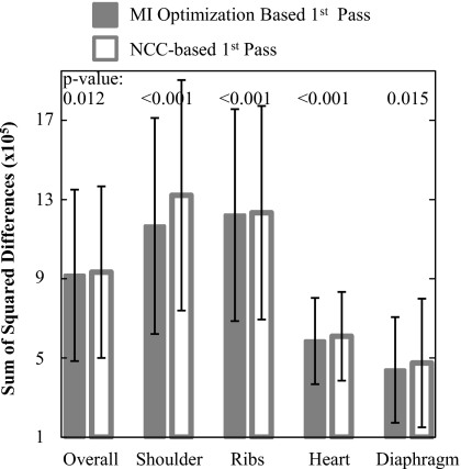
Two studies were conducted to evaluate the objective functions, MI and NCC. The first specifically examined performance in the first pass (n=1). Twenty DE images were randomly chosen from the clinical trial, each registered separately using MI optimization or NCC in pass n=1. Recognizing that comparison in terms of the objective function for the MI optimization approach may bias the results in its favor, a variety of additional figures of merit was considered in analyzing registration performance. These include the sum of squared differences in LE and HE pixel values, coefficient of variation and kurtosis of the difference histogram, and Pearson’s correlation coefficient—all of which yielded fairly consistent trends. The sum of squared differences between LE and HE pixel values, normalized by the number of pixels in the respective subregions, is plotted in Fig. 13. MI-based registration was found to give superior performance demonstrated by a lower sum of squared differences in the overall image as well as the four anatomical subregions. In fact, NCC was frequently observed to decrease registration accuracy (judged qualitatively from DE images and quantitatively from deteriorated figures of merit) in the first pass, whereas MI optimization consistently provided significant improvement. Such behavior in pass n=1 is likely associated with large ROIs that are susceptible to self-similarity and multiple degrees of motion for which NCC is known to be subject to local minima.16 MI optimization addressed this limitation as it is less sensitive to the image intensity distributions and can adequately correct motion over large scales. Therefore, MI optimization was selected as the basis for the first pass (n=1) to ensure good initial conditions for subsequent passes. In addition, MI optimization in pass 1 did not impose serious computational penalties (as shown in Table 1), owing to a small number of ROIs and coarse pixel resolution (bn=16).
Figure 13.
Registration performance in terms of sum of squared differences between LE and HE images, normalized by the number of pixels in respective subregions, after one pass (n=1) of MI optimization or NCC-based registration. MI optimization provided statistically superior performance compared to NCC. The p-values correspond to a paired t-test between 20 cases registered by MI and NCC.
Table 1.
Time (minutes) taken for each pass using MI and NCC optimization. NCC improves computational speed by a factor of ∼6. Measurements were performed in MATLAB software implemented on a desktop PC (Dell Precision 380; 3.00 GHz CPU; 2 GB RAM). Future work will consider GPU-based implementations for registration speed consistent with clinical requirements.
| n | MI optimization | NCC |
|---|---|---|
| Pass 1 | 10.7 | 2.2 |
| Pass 2 | 34.0 | 6.7 |
| Pass 3 | 154.8 | 29.1 |
| Pass 4 | 643.0 | 115.3 |
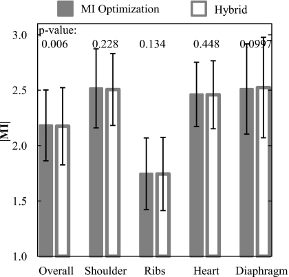
The second study examined the performance of MSMR registration based on MI optimization only (all passes) compared to that of a hybrid approach in which MI optimization was used in pass n=1, followed by NCC in passes 2–4. As shown in Fig. 14, the MI-only and hybrid approaches yielded indistinguishable registration performance in the four subregions (p-values >0.05 in each subregion). While there is weak evidence for improved registration using MI only (p=0.006) in the overall region, DE images resulting from the MI-only and hybrid algorithms were qualitatively indistinguishable. As shown in Table 1, the hybrid algorithm exhibited a significant improvement in computation time (by a factor of ∼6). The advantage in time becomes more pronounced in later passes as the number of ROIs increases. These results motivated the selection of the hybrid algorithm as the nominal choice for all cases considered in the current work, with MI optimization employed in pass 1 and NCC in subsequent passes.
Figure 14.
Registration performance using MI optimization and the hybrid algorithm. There is no statistically significant difference in performance between the two approaches.
References
- Ergun I. D. L., Mistretta C. A., Brown D. E., Bystrianyk R. T., Sze W. K., Kelcz F., and Naidich D. P., “Single-exposure dual-energy computed radiography: Improved detection and processing,” Radiology 174(1), 243–249 (1990). [DOI] [PubMed] [Google Scholar]
- Alvarez R. E., Seibert J. A., and Thompson S. K., “Comparison of dual energy detector system performance,” Med. Phys. 10.1118/1.1645679 31(3), 556–565 (2004). [DOI] [PubMed] [Google Scholar]
- Richard S. and Siewerdsen J. H., “Optimization of dual-energy imaging systems using generalized NEQ and imaging task,” Med. Phys. 10.1118/1.2400620 34(1), 127–139 (2007). [DOI] [PubMed] [Google Scholar]
- McAdams H. P., Samei E., J.DobbinsIII, Tourassi G. D., and Ravin C. E., “Recent advances in chest radiography,” Radiology 10.1148/radiol.2413051535 241(3), 663–683 (2006). [DOI] [PubMed] [Google Scholar]
- Alvarez R. E., Seibert J. A., and Thompson S. K., “Comparison of dual energy detector system performance,” Med. Phys. 10.1118/1.1645679 31(3), 556–565 (2004). [DOI] [PubMed] [Google Scholar]
- Sabol J. M., Avinash G. B., Nicolas F., Claus B., Zhao J., and Dobbins J. T., “The development and characterization of a dual-energy subtraction imaging system for chest radiography based on CsI:Tl amorphous silicon flat-panel technology,” Proc. SPIE 10.1117/12.430897 4320, 399–408 (2001). [DOI] [Google Scholar]
- Kano A., Doi K., MacMahon H., Hassell D. D., and Giger M. L., “Digital image subtraction of temporally sequential chest images for detection of interval change,” Med. Phys. 10.1118/1.597308 21, 453–461 (1994). [DOI] [PubMed] [Google Scholar]
- Ishida T., Ashizawa K., Engelmann R., Katsuragawa S., MacMahon H., and Doi K., “Application of temporal subtraction for detection of interval change in chest radiographs: Improvement of subtraction images using automated initial image matching,” J. Digit Imaging 12, 77–86 (1998). [DOI] [PMC free article] [PubMed] [Google Scholar]
- Ishida T., Katsuragawa S., Nakamura K., MacMahon H., and Doi K., “Iterative image warping technique for temporal subtraction of sequential chest radiographs to detect interval change,” Med. Phys. 10.1118/1.598627 26, 1320–1329 (1999). [DOI] [PubMed] [Google Scholar]
- S. G.ArmatoIII, Doshi D. J., and Engelmann R., “Temporal subtraction of dual-energy chest radiographs,” Med. Phys. 10.1118/1.2163387 33, 1911–1919 (2006). [DOI] [PubMed] [Google Scholar]
- S. G.ArmatoIII, Giger M. L., and MacMahon H., “Automated registration of ventilation∕perfusion images with digital chest radiographs,” Acad. Radiol. 4, 183–192 (1997). [DOI] [PubMed] [Google Scholar]
- S. G.ArmatoIII, Giger M. L., Chen C. T., Vyborny C. J., Ryan J., and MacMahon H., “Automated registration of frontal and lateral radionuclide lung scans with digital chest radiographs,” Acad. Radiol. 7, 530–539 (2000). [DOI] [PubMed] [Google Scholar]
- Viola P. and W. M.WellsIII, “Alignment by maximization of mutual information,” Int. J. Comput. Vis. 10.1023/A:1007958904918 24(2), 137–154 (1997). [DOI] [Google Scholar]
- Collignon A., Maes F., Delaere D., Vandermeulen D., Suetens P., and Marchal G., “Automated multi-modality image registration based on information theory,” in Information Processing in Medical Imaging, edited by Bizais Y., Barillot C., and Paola R. D. (Kluwer, Norwell, MA, 2004), pp. 263–274. [Google Scholar]
- Haralick R. M., and Shapiro L. G., Computer and Robot Vision (Addison-Wesley, Boston, MA, 1992), Vol. II, pp. 316–317. [Google Scholar]
- Zitova B. and Flusser J., “Image registration methods: A survey,” Image Vis. Comput. 10.1016/S0262-8856(03)00137-9 21, 977–1000 (2003). [DOI] [Google Scholar]
- Maintz J. B. A. and Viergever M. A., “A survey of medical image registration,” Med. Image Anal. 2(1), 1–36 (1998). [DOI] [PubMed] [Google Scholar]
- Crum W. R., Hartkens T. and Hill D. L. G., “Non-rigid image registration: Theory and practice,” Br. J. Radiol. 10.1259/bjr/25329214 77, S140–S153 (2004). [DOI] [PubMed] [Google Scholar]
- Hawkes D. J., “Algorithms for radiological image registration and their clinical application,” J. Anat. 10.1046/j.1469-7580.1998.19330347.x 193, 347–361 (1998). [DOI] [PMC free article] [PubMed] [Google Scholar]
- Penney G. P., Weese J., Little J. A., Desmedt P., Hill D. L. G., and Hawkes D. J., “A comparison of similarity measures for use in 2-D–3-D medical image registration,” IEEE Trans. Med. Imaging 10.1109/42.730403 17(4), 586–595 (1998). [DOI] [PubMed] [Google Scholar]
- Pluim J. P. W., Maintz J. B. A., and Viergever M. A., “Mutual-information-based registration of medical images: A survey,” IEEE Trans. Med. Imaging 10.1109/TMI.2003.815867 22(8), 986–1004 (2003). [DOI] [PubMed] [Google Scholar]
- Rosenfeld A. and Vanderbrug G. J., “Coarse-fine template matching,” IEEE Trans. Syst. Man Cybern. 7, 104–107 (1977). [Google Scholar]
- Nelder J. and Mead R. A., “A simplex method for function minimization,” Comput. J. 7, 308–313 (1965). [Google Scholar]
- Lagarias J. C., Reeds J. A., Wright M. H., and Wright P. E., “Convergence properties of the Nelder-Mead simplex method in low dimensions,” SIAM J. Optim. 10.1137/S1052623496303470 9 (1), 112–147 (1998). [DOI] [Google Scholar]
- Studholme C., Hill D. L. G., and Hawkes D. J., “An overlap invariant entropy measure of 3D medical image alignment,” Pattern Recogn. 10.1016/S0031-3203(98)00091-0 32(1), 71–86 (1999). [DOI] [Google Scholar]
- Goshtasby A., “Image registration by local approximation methods,” Image Vis. Comput. 10.1016/0262-8856(88)90016-9 6, 255–261 (1988). [DOI] [Google Scholar]
- Siewerdsen J. H., Shkumat N. A., Dhanantwari A. C., Williams D. B., Richard S., Daly M. J., Paul N. S., Moseley D. J., Jaffray D. A., Yorkston J., and Van Metter R., “High-performance dual-energy imaging with a flat-panel detector: Imaging physics from blackboard to benchtop to bedside,” Proc. SPIE Phys. Med. Imag. 6142, 61421E (2006). [Google Scholar]
- Shkumat N. A., Siewerdsen J. H., Dhanantwari A. C., Williams D. B., Richard S., Tward D. J., Paul N. S., Yorkston J., and Van Metter R., “Development and implementation of a high-performance, dual-energy imaging system,” Proc. SPIE Phys. Med. Imag. 6510, 651006 (2007). [Google Scholar]
- Shkumat N. A., Siewerdsen J. H., Dhanantwari A. C., Williams D. B., Richard S., Paul N. S., Yorkston J., and Van Metter R., “Optimization of image acquisition techniques for dual-energy imaging of the chest,” Med. Phys. 34(10), 3904–3915 (2007). [DOI] [PubMed] [Google Scholar]
- Sabol J. M., Liu R., Saunders R., Markley J., Moreno N., Seamans J., Wiese S., and Jabri K., “The impact of cardiac gating on the detection of coronary calcifications in dual-energy chest radiography: A phantom study,” Proc. SPIE 10.1117/12.653387 6142, 61421F (2006). [DOI] [Google Scholar]
- Xu T., Ducote J. L., Wong J. T. and Molloi S., “Feasibility of real time dual-energy imaging based on a flat panel detector for coronary artery calcium quantification,” Med. Phys. 10.1118/1.2198942 33(6), 1612–1622 (2003). [DOI] [PubMed] [Google Scholar]
- Shkumat N. A., Siewerdsen J. H., Dhanantwari A. C., Williams D. B., Paul N. S., Yorkston J., and Van Metter R., “Cardiac gating with a pulse oximeter for dual-energy imaging,” Phys. Med. Biol. 53, 6097–6112 (2008). [DOI] [PubMed] [Google Scholar]
- Samei E., Flynn M. J., and Reimann D. A., “A method for measuring the presampled MTF of digital radiographic systems using an edge test device,” Med. Phys. 10.1118/1.598165 25, 102–113 (1998). [DOI] [PubMed] [Google Scholar]
- Fujita H., Tsai D., Itoh T., Doi K., Morishita J., Ueda K., and Qhtsuka A., “A simple method for determining the modulation transfer function in digital radiography,” IEEE Trans. Med. Imaging 10.1109/42.126908 11, 34–39 (1992). [DOI] [PubMed] [Google Scholar]
- Yotam E., Ephi P., and Ami Y., “MTF for Bayer pattern color detector,” Proc. SPIE 10.1117/12.723140 6567, 65671M (2007). [DOI] [Google Scholar]
- Warp R. J. and J. T.DobbinsIII, “Quantitative evaluation of noise reduction strategies in dual-energy imaging,” Med. Phys. 10.1118/1.1538232 30, 190–198 (2003). [DOI] [PubMed] [Google Scholar]
- MacMahon H., Li F., Engelmann R., Roberts R., and Armato S., “Dual energy subtraction and temporal subtraction chest radiography,” J. Thorac. Imaging 23, 77–85 (2008). [DOI] [PubMed] [Google Scholar]
- Ide K., Murakami T., Higashino H., Mochizuki T., Tagashira H., and Arakawa K., “The Evaluation of the ECG-gating Method Using Dual-exposure Dual-energy Subtraction Chest Radiography with Flat-panel Detector,” in RSNA, Chicago IL: (2006).


