

Abstract
Primary growth is characterized by cell expansion facilitated by water uptake generating hydrostatic (turgor) pressure to inflate the cell, stretching the rigid cell walls. The multiple source theory of root growth hypothesizes that root growth involves transport of water both from the soil surrounding the growth zone and from the mature tissue higher in the root via phloem and protophloem. Here, protophloem water sources are used as boundary conditions in a classical, three-dimensional model of growth-sustaining water potentials in primary roots. The model predicts small radial gradients in water potential, with a significant longitudinal gradient. The results improve the agreement of theory with empirical studies for water potential in the primary growth zone of roots of maize (Zea mays). A sensitivity analysis quantifies the functional importance of apical phloem differentiation in permitting growth and reveals that the presence of phloem water sources makes the growth-sustaining water relations of the root relatively insensitive to changes in root radius and hydraulic conductivity. Adaptation to drought and other environmental stresses is predicted to involve more apical differentiation of phloem and/or higher phloem delivery rates to the growth zone.
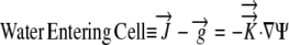
Plant growth involves water uptake by the cells and expansion of the cell walls under the resultant turgor (internal hydrostatic pressure). The water uptake and increase in cell volume are accompanied by nutrient and metabolite deposition. Thus, hydraulics of growth (i.e. the energies, conductivities, and fluxes of water in growing tissue) are fundamental to understanding primary plant growth. Quantitatively, the driving force for water movement in the plant, as in other porous media, is considered to be the gradient in water potential (Ψ), an energy per unit volume given in MPa. Thus, primary growth can be modeled by considering plant tissue to be a distributed sink for water, with low Ψ and/or high hydraulic conductivity driving water deposition into rapidly expanding regions. Molz and Boyer (1978) developed the theoretical basis for predicting the radial water flux in one dimension within the intercalary meristem of growing soybean (Glycine max) hypocotyls. In this aerial tissue, water moves from the xylem both outward to the epidermis and inward to the pith. Thus, in the growing hypocotyls, Ψ is predicted to be least negative in the xylem and to decrease toward the epidermis and the pith. These predictions for growth-induced or growth-sustaining Ψ were confirmed when the experimental technology became sensitive enough to detect the gradients in Ψ (Nonami and Boyer, 1993). Passioura and Boyer (2003) expanded the theory to incorporate anatomical detail and corresponding spatial patterns of hydraulic conductivity. Their model explains experimental results on water relations during growth transients for many areas of the plant.
The hydraulics of root growth differ from shoot growth because of differences in xylem anatomy. Root xylem becomes functional perhaps 1 cm behind the tip and well behind the growth zone. To enter the growing cells near the maize (Zea mays) root tip, externally supplied metabolites must move several millimeters without phloem (Fig. 1), and any water supplied by functional xylem would need to move more than 1 cm. Silk and Wagner (1980) provided a theoretical framework for a two-dimensional treatment of the growth-sustaining Ψ gradients in maize roots. They assumed that the water source was external (the soil or root-bathing medium) and that the root surface was in equilibrium with the soil or bathing medium, so that the flow path to growing cells in the root was predicted to be primarily inward. As in the shoot model, growing tissue was seen as a distributed sink for water. However, since the publication of that theory, experimental studies have revealed that the root tip is not in equilibrium with the bathing medium (Pritchard et al., 1996, 2000; Gould et al., 2004; Shimazaki et al., 2005). Pressure probes combined with osmotic potential determinations have shown that the Ψ of exterior root cells ranges from −0.17 to −0.6 MPa, depending on environmental conditions. This range is more negative than in the nutrient medium. Furthermore, evidence has accumulated that at least some water for root growth comes from the phloem. The most obvious evidence is perhaps the growth of nodal (adventitious) roots of maize, rice (Oryza sativa), and other gramineous plants (Westgate and Boyer, 1985). This growth is a normal part of crop development. The nodal roots grow through air and then dry layers of surface soil, making it unlikely that the expanding root cells obtain water from the dry media surrounding the root. Empirical and theoretical studies have concluded that the phloem probably provides water for growth of the primary maize root (Bret-Harte and Silk, 1994; Frensch and Hsiao, 1995; Pritchard, 1996; Pritchard et al., 1996, 2000; Hukin et al., 2002; Gould et al., 2004).
Figure 1.

Primary root growth zone. The tip of the seedling root of maize showing the meristem as part of the apical third of the elongation zone. The boundary of this root section was digitized to provide the computational body-fit grid used for the model. [See online article for color version of this figure.]
The model described here follows the concepts of Pritchard and colleagues (1996, 2000) in assuming a pressure-driven bulk flow of solution through the phloem to the region where phloem is beginning to be functional (1–4 mm from the apex; Fig. 1). Water movement can occur from both the surrounding soil and the developing phloem. Henceforth, we refer to the “external water source equilibrium” or EE model, for which the boundary condition is solely an exterior medium of fairly high Ψ (−0.005 to −0.05 MPa) and no conditions are placed on the phloem Ψ (Table I). This EE model assumes, as did Silk and Wagner (1980), that the exterior of the root is in equilibrium with its bathing solution. Empirical studies have shown that this model is not realistic, because the root maintains peripheral cells at more negative Ψ than the bathing medium. Since this is hypothesized to occur by deposition of apoplastic solutes, we will refer to a model with external water source and apoplastic solutes near the exterior as the EASE model.
Table I.
Acronyms for models and definitions of symbols used in mathematical modeling
| Acronym | Boundary Condition | |
|---|---|---|
| EE | External water source Equilibrium | |
| EASE | External water source and Apoplastic Solutes near the Exterior | |
| PEWS | Phloem and External Water Sources | |
| Symbol | Physical Significance | Units |
| L | Relative elemental growth rate 
|
h−1 |
 |
Growth velocity vector | mm h−1 |
 |
Water flux vector | mm h−1 |
 |
Hydraulic conductivity tensor | mm2 s−1 MPa−1 |
| Ψ | Total water potential | MPa |
 |
Unit normal to the surface | |
| s | Control surface | mm2 |
| V | Control volume | mm3 |
| r | Radial coordinate | mm |
| z | Longitudinal coordinate | mm |
| x, y | Cartesian coordinates | mm |
| J | Jacobian Matrix of Transformation | |
A “multiple source” model places boundary conditions on the Ψ of both the bathing medium and the phloem to simulate both external and internal source activity, so we will refer to this model as the PEWS (for phloem and external water sources) model.
THEORETICAL BACKGROUND FOR THE MULTIPLE SOURCE MODEL
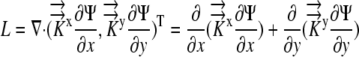
Relationship between Growth and Ψ
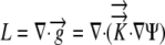
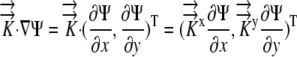
The relative elemental growth rate (L), equal to the divergence of the growth velocity ( ), is a measure of the local growth rate (see Table I for variable definitions). Following Silk and Wagner (1980), it is assumed that water moves via a version of Darcy's law relating water flux to the gradient in Ψ. To cross a cell wall and inflate the cell, water velocity (
 ) must be greater than the velocity
  with which the cell wall is being displaced during growth.
 |
By the Reynolds transport theorem, in three dimensions
 |
By the divergence theorem
 |
Since water is incompressible,  and L can be related to the local Ψ required to drive the growth-sustaining water influx:
 |
(1) |
The velocity with which a cell moves depends on the rate at which it is displaced by those cells behind it and its own expansion. If the divergence of velocity is 0, the cell is simply displaced and not actually expanding. Equation 1 predicts that in the absence of a Ψ gradient there would be no expansion. More generally, the governing equations (1) can be used to calculate the growth-sustaining Ψ using experimental data for the L and hydraulic conductivity (Silk and Wagner, 1980; Boyer and Silk, 2004).
Assumptions
The PEWS model extends the previous external root growth model by including the assumption that some water is being supplied from nongrowing tissue via the root phloem and protophloem. The phloem develops closer to the root tip than the xylem and channels water from the mature regions into the growth zone (Bret-Harte and Silk, 1994; Frensch and Hsiao, 1995; Pritchard, 1996; Pritchard et al., 2000). We assume the following.
(1) The root tissue is cylindrical beyond the parabolic root tip, with radius r. Growth is radial and longitudinal near the maize root tip and in the direction of the long axis z beyond z = 2 mm.
(2) The growth pattern does not change in time.
(3) Conductivities in the radial (
 r) and longitudinal (
 z) directions are independent, so radial flow is not modified by longitudinal flow.
(4) The water needed for primary root growth is obtained from both the surrounding growth medium and the internal protophloem sources. In our PEWS model, this assumption is embodied by maintaining the bathing medium Ψ close to zero (Ψ = −0.05 MPa in many empirical studies) and the protophloem Ψ less negative than the interior cells (Ψ = −0.20 MPa; Pritchard et al., 1996).
(5) For both the EASE and the PEWS models, the cells at the periphery of the root growth zone have a total Ψ gradient as measured by Pritchard et al. (1996), increasing from −0.27 MPa below z = 2.5 mm to −0.15 MPa at z = 12 mm.
Numerical Approach
The governing equations (1) were converted to three-dimensional generalized coordinates, a method that converts grid components (x, y, z) into orthogonal, equally spaced grid components (ξ, η, ζ) related by the Jacobian matrix of the transformation and a converted generalized equation (Fletcher, 1991). (This model does not convert the governing equations into a radial coordinate system, which was the approach used by Silk and Wagner [1980] and Boyer and Silk [2004].) A second order finite difference approximation is used to solve the given generalized governing equations on the computational orthogonal grid. A literature review resulted in estimates of radial hydraulic conductivity in the range 7.3 × 10⁻¹¹ m2 s−1 MPa−1 <  < 5 × 10⁻¹⁰ m2 s−1 MPa−1. We choose
  = 1.3 × 10⁻¹⁰ m2 s−1 MPa−1 as a reference value from the empirical value of Frensch and Hsiao (1995). For more details, see “Materials and Methods.”
RESULTS
The three models predict different distributions of growth-sustaining Ψ in the root tip (Figs. 2 and 3). Figure 2 provides a two-dimensional summary of the three-dimensional results of the models by showing the median longisection (not to scale) with the calculated Ψs. The coloring or shading of all plots is contoured for Ψ relative to the minimal Ψ value, with the colors starting in blue at Ψ = 0 (pure water) and decreasing in value to Ψmin = −0.35 MPa (red or darkest gray). The EE and EASE models (Fig. 2, A and B, respectively) produce a shallow gradient in growth-sustaining Ψ. In a root median longisection, the spatial pattern of Ψ has egg-shaped isopotential regions. The potential is most negative in the center of the root and at the region of fastest growth rate. The flux of the water pathway (Fig. 2, A and B, directional arrows) is primarily inward radial water movement from the external soil water source, with velocity of water movement decreasing with distance from the source at the boundary. The flux is also related to the growth pattern (L; see Fig. 8D), with no water flux at the top boundary (z = 10 mm) where L = 0 h−1 and a gradual increase of flux with an increase of growth leading to maximum flux occurring at the area of maximum growth.
Figure 2.

Model predictions of growth-sustaining Ψ (MPa) displayed as a color or gray scale map (scale above the panels) on a median longisection through the growth zone. Direction of flux of the water pathway is denoted by arrows of equal length. A, EE model (external source, root in equilibrium with bathing medium). B, EASE model (external source, gradient at root boundary). C, PEWS model (external and phloem sources, gradient at root boundary). [See online article for color version of this figure.]
Figure 3.

Model predictions of growth-sustaining Ψ displayed on three-dimensional views of radial cross-sections. Legend is as for Figure 2. [See online article for color version of this figure.]
Figure 8.

The computational root grid with protophloem source grid placement. A, Three-dimensional (x, y, z) view of the root grid (not to scale). B, Two-dimensional (x, z) view of the longitudinal section for the internal parabolic grid at z = 2.0 mm. C, Two-dimensional (x, z) view of the longitudinal section for the internal radial grid with the protophloem source grid placement. D, Relative elemental growth rate values (L) shown on the z distance scale used in A and B. E, Two-dimensional radial transverse (x, y) of the modified H-grid used in modeling the internal radial grid with rmax = 0.5 mm. The protophloem sources, each with a radius of 0.07 mm, are placed asymmetrically as shown. [See online article for color version of this figure.]
The key difference between the EE and EASE results are shown in the coloration or shading of the gradient. For the EE model, the root tissue Ψ remains close in value to the bathing solution (Figs. 2A and 3A). These results replicate the values produced by the computational methods and boundary values used by Silk and Wagner (1980); thus, Figures 2A and 3A indicate that the more powerful program developed for this study is capable of generating the results of earlier approaches. However, this solution does not resemble the results of empirical studies. Instead, we look to the EASE model, imposing a boundary condition that is a steep differential between the Ψ of the exterior cells and the bathing solution. The results produce a steep gradient in growth-sustaining Ψ, with the root interior reaching Ψ = −0.35 MPa (Figs. 2B and 3B).
The multiple source or PEWS model assumes that there is an additional water source supplied from the protophloem. Thus, the PEWS model imposes an additional boundary condition, Ψ = −0.2 MPa, where phloem and protophloem are present. The results of this model are seen in Figures 2C and 3C. In a root median longisection (Fig. 2C), the spatial pattern of Ψ no longer has the egg-shaped isopotential regions (Fig. 2, compare B and C). The magnitude of the growth-sustaining Ψ gradient is considerably less than required by the EASE model (Fig. 3, compare B and C). Comparing the flux reveals that for both EASE and PEWS, water movement (flux) decreases with distance from the source. However, in the area of maximum growth, EASE predicts that the water moves mostly inward. In contrast, in PEWS there is both outward flux from the protophloem and inward radial water movement from the external water source (see flux arrows in Fig. 2, B and C). The PEWS model results in a Ψ field closest to that found by Pritchard et al. (2000) and Hukin et al. (2002).
Sensitivity Analysis
The mathematical models were used to determine the sensitivity of the growth-sustaining Ψ field to morphological, anatomical, and hydraulic parameters: root radius (rmax), the length and position of the phloem source, and hydraulic conductivity ( ) as described in Table II. The results demonstrate that the magnitude of the growth-sustaining Ψ value becomes much less sensitive to root radius and hydraulic conductivity when phloem sources are included; that is, PEWS gives radial Ψ gradients that are not much influenced by root radius or a change in
  . However, the growth-sustaining Ψ is particularly sensitive to the location of phloem differentiation. To assess the importance of the phloem anatomy, we first assumed that all phloem and protophloem within the growth zone acts as a source and tested the effect of the source length (i.e. we solved Eq. 1 assuming phloem differentiation at different distances from the tip). As the length of the phloem source is made shorter (the location to which phloem supplies water is decreased from z = 1 mm to z = 6.1 mm), Ψmin becomes more negative (Fig. 4). The shorter the source is, the more closely the results of the PEWS model resemble those of the EASE model (Fig. 4E). It is not known whether all of the phloem in the growth zone provides water (extended phloem source) or whether a short zone of developing protophloem provides the osmotically dilute solution (limited phloem source). Figure 5 shows the effect of 1-mm-long phloem sources located at different distances from the apex. If the source is found 1 mm from the tip, the most negative Ψ is found in the region distal to 2 mm. If the protophloem acts as a water source 3 mm from the tip, the more negative Ψ is found in the region apical to the source. If the source extends from 4 to 5 mm, the PEWS model closely resembles the EASE model. These profiles show that the limited phloem sources have a very local influence over the Ψ of the root. At the end of the source, the Ψ values quickly (within less than 1 mm) come to approximate the values of the EASE model.
Table II.
Sensitivity analysis test values
Variable values tested for the mathematical model sensitivity analysis. Boldface values were those used to calculate typical root growth condition results.
| Variable | Physical Significance | Values Tested |
|---|---|---|
| rmax | Maximum root radius at z = 10 mm | rmax = 0.3 mm, 0.5 mm, 0.7 mm |
| phloem_stop | Distance from root tip that the protophloem source extends into the growth zone (mm) | phloem_stop = 2.1 mm, 4.1 mm, 6.1 mm |
 |
Hydraulic conductivity |
K:  1.3×10⁻¹⁰ m−1 s−1 MPa−1 1.3×10⁻¹⁰ m−1 s−1 MPa−1
|
K9:  =1.3×10⁻⁹ m−1 s−1 MPa−1 =1.3×10⁻⁹ m−1 s−1 MPa−1
|
||
K11:  =1.3×10⁻¹¹ m−1 s−1 MPa−1 =1.3×10⁻¹¹ m−1 s−1 MPa−1
|
||
| L | Relative elemental growth rate | See Figure 8D for data used in simulations |
| rs | Radius of protophloem sources | rs = 0.07 mm |
| ra | Radial distance of sources from the center axis | ra= rmax/4 |
| Ψs | Ψ value of source cells | Ψs = 0 MPa, –0.2 MPa (Pritchard, 1996; Pritchard et al., 1996), −0.46 MPa (Warmbrodt, 1987) |
| Ψboundary | Ψ value of root boundary | Varies from −0.27 MPa for z = 2.5 mm, increasing (becoming less negative) to −0.15 MPa at z = 12 mm (Pritchard et al., 1996) |
| Ψsoln | Ψ value of solution boundary | Ψsoln = −0.005 MPa (Pritchard et al., 1996) |
Figure 4.

Effect of the extent of internal source shown by the PEWS model with different locations for the start of the phloem source. A, Location 1 mm from tip. B, Location 2.1 mm from tip. C, Location 4.1 mm from tip. D, Location 6.1 mm from tip. E, EASE model (no phloem sources). [See online article for color version of this figure.]
Figure 5.

Effect of internal source limited to 1 mm in length shown by the PEWS model with the limited source located at different distances from the tip: 1 to 2 mm (A), 2 to 3 mm (B), 3 to 4 mm (C), and 4 to 5 mm (D). [See online article for color version of this figure.]
Although the Ψ values for all three models are sensitive to hydraulic conductivity, it requires variation of 2 orders of magnitude to see a substantial effect when phloem sources exist. In contrast, the EASE model indicates large effects of  on the Ψ field (Fig. 7A). Thus, in Figures 6 and 7A, we see that when
  decreases by 2 orders of magnitude (from 10−9 to 10−11 m2 s−1 MPa−1), PEWS shows that Ψmin declines by only 0.15 MPa while with EASE the Ψmin declines by an additional 0.50 MPa. Interestingly, the presence of phloem sources also makes the Ψ field much less sensitive to root radius (Fig. 7B) for PEWS. An increase of root radius from 0.3 to 0.7 mm causes a progressive decrease in interior Ψ with EASE but hardly changes the radial pattern of growth-sustaining Ψ for the PEWS model (Fig. 7B).
Figure 7.

Radial profiles of Ψ showing how the presence of phloem water sources produces different sensitivities to hydraulic conductivity and root radius. EASE model results are shown with dashed lines, and PEWS model results are shown with solid lines. A, Hydraulic conductivity values color coded as shown. K9 represents  . K represents
  . K11 represents
  . B, Root radius color coded as shown for 0.3, 0.5, and 0.7 mm. [See online article for color version of this figure.]
Figure 6.

Sensitivity analysis for the effect of hydraulic conductivity on growth-sustaining Ψ. The PEWS model was used assuming radial and longitudinal hydraulic conductivities equal to 1.3 × 10⁻⁹ m2 s−1 MPa−1 (A), 1.3 × 10⁻¹⁰ m2 s−1 MPa−1 (B), and 1.3 × 10⁻¹¹ m2 s−1 MPa−1 (C). [See online article for color version of this figure.]
DISCUSSION
The multiple source model developed here has more powerful numerics, full three-dimensional treatment, and more computational power than was available in older models. The results of the previous model of Silk and Wagner (1980) were replicated. The PEWS or multiple source root growth model extends the previous external source root growth model by incorporating boundary conditions consistent with the empirical evidence that the exterior cells of the root growth zone have considerably lower Ψ than the bathing solution. This recognition of disequilibrium between root and soil solution Ψ parallels ecological studies emphasizing that predawn plant Ψ, including leaf Ψ and root xylem Ψ, are often more negative than root zone soil Ψ (Donovan et al., 2001; James et al., 2006). Our PEWS model also includes the new assumption that there is an additional water source that is transporting water into the growth zone via the protophloem. Within root-growing regions, it is commonly observed that turgor and osmotic gradients are rather uniform across the root radius during steady growth (Spollen and Sharp, 1991; Pritchard et al., 2000). The results of PEWS are consistent with these empirical results.
The assumption of internal water sources is also consistent with work showing transport of water and sugars from protophloem to the more apical root tissue (Hukin et al., 2002; Gould et al., 2004) and effects of light intensity on sugar transport and associated growth rate patterns in roots (Muller et al., 1998; Nagel et al., 2006). The new results also support the concept of the hydraulic isolation of the growth zone, as our thermodynamic transport model replicates an empirical study showing that apical regions of maize roots are not affected by negative Ψs in mature, more distal regions (Zwieniecki et al., 2003).
The sensitivity analysis explains several adaptive morphological features if we assume that a small growth-sustaining Ψ gradient facilitates growth under stressful conditions. As the phloem initiation sites become farther from the root tip (and the length of nonvascularized tissue in the growth zone becomes longer), the growth-sustaining Ψ gradients become larger and the PEWS solution approximates the EASE model. These results indicate the adaptive value of one of the known physiological responses to water stress: more apical vasculature development (Beauchamp and Lathwell, 1966). Surprisingly, the presence of phloem water sources makes the growth-sustaining water relations of the root rather immune to changes in root radius. Thus, the reported thinning of roots under water stress (Sharp et al., 1988) may be adaptive as a way to produce osmotic adjustment or to economize carbon allocated for elongation, rather than as a way to permit growth with small Ψ gradients. A related insight is that the commonly observed thickening of roots growing in hard soils would not necessitate enormous changes in growth-sustaining Ψs. Growth of the thicker root tips would be facilitated by increased flux to root protophloem and more apical differentiation of the phloem.
The PEWS model could be extended to explore the hydraulic interactions between root and soil if our model is embedded in a porous matrix with appropriate properties: hydraulic conductivity that decreases with water content and flow governed by Darcy's law. This is a complicated problem numerically but worthy of future study. The millimeter-to-meter scale of our approach would provide information on the relationships of soil hydraulic properties to growth and would be a useful complement to larger scale models that have shown complex time-dependent patterns of soil water depletion around root systems (Clausnitzer and Hopmans, 1994; Garrigues et al., 2006).
MATERIALS AND METHODS
Root Grid
To facilitate the numerical approach to this problem, a body-fitted grid was created that approximates an average maize root (Figs. 1 and 8). The outer grid surface was generated by averaging the boundary coordinates of maize roots in micrographs. The internal computational grids were created using a parabolic longitudinal grid combined with a modified cross-sectional H-grid (Fig. 8).
Solving for Ψ
The governing equation (1) was converted to a three-dimensional generalized coordinate partial differential equation. Finite difference approximation was used to convert the partial differential equation into a linear system of equations, represented in matrix form by:
 |
(2) |
This matrix equation is used to solve for the unknown internal Ψ values [Ψ(i,j,k)] using the known L [L(i,j,k)] and the calculated sparse coefficient matrix [Coeff]. Matlab was used to solve the matrix system via the biconjugate gradient method.
Details of the numerical approach are presented for two dimensions. The extension to three dimensions is straightforward.
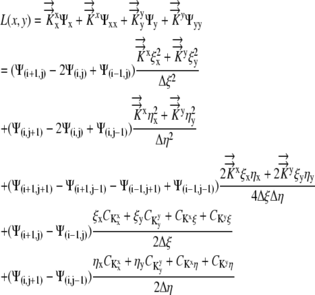
Generalized Coordinates Applied to Equation 1
Recall from Equation 1, the two-dimensional equation in Cartesian coordinates for Ψ is given by:  , where
  .
.
 |
(3) |
Thus
 |
(4) |
 |
(5) |
Using the notation  as the x partial derivative of Ψ and
  as the second partial derivative of Ψ, Equation 5 becomes:
 |
(6) |
For the generalized coordinates, ξ and η, we have  by the chain rule. Since the equations for other variables are similar, we will only present the generalized coordinate transformation for x.
 |
(7) |
 |
(8) |
Denoting the Jacobian matrix of transformation by J and differentiating the right hand side of Equation 8 by parts, we get:
 |
(9) |
Proceeding in a similar manner with the other variables results in an additional set of equations similar to Equation 9 that can be substituted into Equation 6 to get a formula for L.
Finite Difference Applied to Equation 9
Second order finite difference approximations are used to approximate the derivatives, resulting in:
 |
(10) |
where discretization in the x direction is denoted by Ψi, discretization in the y direction is denoted by Ψj, and
 |
(11) |
Collecting terms on the right side:
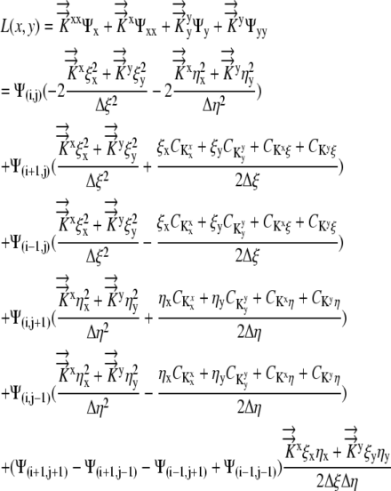 |
(12) |
The values for L(x,y),  , and
, and  are given and the values for Δη and Δξ are determined by the grid. From this, we can calculate
  Thus, Equation 12 reduces to Equation 2, [Coeff]Ψ = L. Now the system is modified to reflect the flux boundary condition.
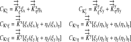
Three-Dimensional Model of Root Growth with the Flux Boundary
Pritchard et al. (1996) recorded an osmotic gradient that ran the length of the root, ranging linearly from −0.27 MPa at 2.5 mm to about −0.15 MPa at 12 mm from the tip. This gradient motivated an expansion of the three-dimensional EE model to include a flux boundary condition. The resulting model was derived in two dimensions and then extended for three-dimensional implementation, which consists of the following two equations:
 |
(13a) |
 |
(13b) |
Since the flux is in the radial direction, Equation 13b is replaced by
 |
(14) |
where
 |
(15) |
given 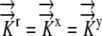 .
.
Writing the flux boundary in generalized coordinates, recalling that  , we have:
 |
(16) |
Substituting into Equation 15, we obtain:
 |
(17) |
This flux condition is being forced on the boundary of the grid where either Ψξ = 0 or Ψη = 0. At the boundary Ψξ = 0, we can solve for Ψη:
 |
(18) |
 |
(19) |
Approximating Ψ with the second order finite difference boundary approximations, we get:
 |
(20) |
which results in:
 |
(21) |
A similar process is applied at the other borders to obtain:
 |
(22a) |
 |
(22b) |
 |
(22c) |
 |
(22d) |
The values for  ,
,  , and
, and  and the boundary points
  and
and  are known. The values of
  are again determined by the grid. This flux equation is reflected in the following new coefficient matrix.
 |
(23) |
Comments on the Computational Flux Grids
Although the H-grid worked well for most of our simulations, it was not a good computational grid for the implementation of the flux condition. In order to address this, a new flux computational grid was used (Fig. 8) with two radial rings added at a distance of Δr and 2Δr around the H-grid. In this grid system, the outside ring was associated with the growth medium (Ψsoln) and the inner ring was associated with the boundary of the growing root.
Solving the Two-Dimensional Method
For the flux boundary condition, the resulting matrix equations are as follows:
 |
(24a) |
 |
(24b) |
Adding the two systems gives:
 |
(25) |
This resulting matrix equation incorporates the flux boundary condition and can be solved for the Ψ. This system is again sparse and is very large. The Matlab implementation uses an iterative biconjugate gradient method to solve for Ψ. This approach was faster then the previous direct solver and resulted in a solution within a tolerance of 10−6 (Trefethen and Bau, 1997).
Experimental Data
A hydroponically grown maize (Zea mays) root was modeled. The average primary growth zone for this root is 10 mm long, with an average root radius of 0.5 mm within the elongation zone. The average width of the phloem source tubes was a harder number to calculate. In reviewing the vascular system physiology literature, many references refer to the difficulty of defining the protophloem radius due to the small number of cells involved. The best reference for source radius estimate was Beauchamp and Lathwell (1966), who estimated 17 to 24 sieve tubes per transverse section in the 1.5-mm root radius at 2.5 cm from the root tip. This information, combined with the estimate of sieve element having a radius of 5 to 10 μm, was used to estimate protophloem source radius of 0.16 to 0.06 mm. The sources were then placed, with given radii, in a pentidiagonal (nonaxially symmetric) pattern around the root cross-section (Fig. 8) and modeled to extend to within 1 mm of the root tip. The source value Ψ is Ψ = −0.2 MPa, which maintains the protophloem Ψ less negative than the interior cells (Pritchard, 1996).
L
Marking experiments can be found in the literature to establish L. Here, the data were extended to the computational grid spacing using a cubic spline interpolation (Fig. 8D; Erickson and Sax, 1956; Boyer and Silk, 2004; Silk and Wagner, 1980).
K→→
A literature review resulted in estimates of radial hydraulic conductivity in the range 7.3 × 10⁻¹¹ m2 s−1 MPa−1 <  < 5 × 10⁻¹⁰ m2 s−1 MPa−1 (Ginsburg and Ginzburg, 1970; Bret-Harte and Silk, 1994; Frensch and Hsiao, 1995). The empirically based calculation of Frensch and Hsiao (1995),
  = 1.3 × 10⁻¹⁰ m2 s−1 MPa−1, is used in the reference calculations. The radial and longitudinal hydraulic conductivities are assumed to be independent, with possible spatial variation. Hydraulic conductivity of roots would be expected to vary with growth conditions and to be especially sensitive to plant water status and associated environmental conditions. Note that our transport coefficients are phenomenological rather than mechanistic, as we use a bulk tissue coefficient and have neglected cell structure. Nevertheless, the validity of the model is supported by early demonstrations that coupled flows in apoplasm and symplasm result in water movement that follows the simple transport law (Molz, 1976).
Root Growth Conditions
The root growth medium defines the model boundary conditions. Models assumed laboratory hydroponic growth, with a solution boundary condition (Ψ = −0.02 MPa; Spollen and Sharp, 1991). For the internal boundary (at z = 10 mm), the governing equations (1) were used to solve for the cross-section boundary Ψ values.
Sensitivity Analysis
A physiology sensitivity analysis was conducted using the multiple source model. See Table II for the range of physiological variables that were tested, including maximum root radius, hydraulic conductivity, and growth rate.
This work was supported by the National Science Foundation (Vertical Integration of Research and Education grant no. DMS–0135345).
The author responsible for distribution of materials integral to the findings presented in this article in accordance with the policy described in the Instructions for Authors (www.plantphysiol.org) is: Wendy K. Silk (wksilk@ucdavis.edu).
Some figures in this article are displayed in color online but in black and white in the print edition.
Open Access articles can be viewed online without a subscription.
References
- Beauchamp E, Lathwell DJ (1966) Root-zone temperature effects on the vascular development of adventitious roots in Zea mays. Bot Gaz 127 153–158 [Google Scholar]
- Boyer JS, Silk WK (2004) Hydraulics of plant growth. Funct Plant Biol 31 761–773 [DOI] [PubMed] [Google Scholar]
- Bret-Harte MS, Silk WK (1994) Nonvascular, symplasmic diffusion of sucrose cannot satisfy the carbon demands of growth in the primary root tip of Zea mays. Plant Physiol 105 19–33 [DOI] [PMC free article] [PubMed] [Google Scholar]
- Clausnitzer V, Hopmans JW (1994) Simultaneous modeling of transient three-dimensional root growth and soil water flow. Plant Soil 164 299–314 [Google Scholar]
- Donovan LA, Linton MJ, Richards JH (2001) Predawn plant water potential does not necessarily equilibrate with soil water potential under well-watered conditions. Oecologia 129 328–335 [DOI] [PubMed] [Google Scholar]
- Erickson RO, Sax KB (1956) Rates of cell division and cell elongation in the growth of the primary root of Zea mays. Proc Am Philos Soc 100 499–514 [Google Scholar]
- Fletcher CAJ (1991) Computational Techniques for Fluid Dynamics: Specific Techniques for Different Flow Categories, Ed 2, Vol 2. Springer-Verlag, Berlin
- Frensch J, Hsiao TC (1995) Rapid response of the yield threshold and turgor regulation during adjustment of root growth to water stress in Zea mays. Plant Physiol 108 303–312 [DOI] [PMC free article] [PubMed] [Google Scholar]
- Garrigues E, Doussan C, Pierret A (2006) Water uptake by plant roots. I. Formation and propagation of a water extraction front in mature root systems as evidenced by 2D light transmission imaging. Plant Soil 283 83–98 [Google Scholar]
- Ginsburg H, Ginzburg BZ (1970) Radial water and solute flows in roots of Zea mays. J Exp Bot 21 580–592 [Google Scholar]
- Gould N, Thorpe MR, Minchin PE, Pritchard J, White PJ (2004) Solute is imported to elongation root cells of barley as a pressure driven flow of solution. Funct Plant Biol 31 391–397 [DOI] [PubMed] [Google Scholar]
- Hukin D, Doering-Saad C, Thomas CR, Pritchard J (2002) Sensitivity of cell hydraulic conductivity to mercury is coincident with symplasmic isolation and expression of plasmalemma aquaporin genes in growing maize roots. Planta 215 1047–1056 [DOI] [PubMed] [Google Scholar]
- James JJ, Alder NN, Muhling KH, Lauchli AE, Shackel KA, Donovan LA, Richards JH (2006) High apoplastic solute concentrations in leaves alter water relations of the halophytic shrub, Sarcobatus vermiculatus. J Exp Bot 57 139–147 [DOI] [PubMed] [Google Scholar]
- Molz FJ (1976) Water transport through plant tissue: the apoplasm and symplasm pathways. J Theor Biol 59 277–292 [DOI] [PubMed] [Google Scholar]
- Molz FJ, Boyer JS (1978) Growth-induced water potentials in plant cells and tissues. Plant Physiol 62 423–429 [DOI] [PMC free article] [PubMed] [Google Scholar]
- Muller B, Stosser M, Tardieu F (1998) Spatial distributions of tissue expansion and cell division rates are related to irradiance and to sugar content in the growing zone of maize roots. Plant Cell Environ 21 149–158 [Google Scholar]
- Nagel KA, Schurr U, Walter A (2006) Dynamics of root growth stimulation in Nicotiana tabacum in increasing light intensity. Plant Cell Environ 29 1936–1945 [DOI] [PubMed] [Google Scholar]
- Nonami H, Boyer JS (1993) Direct demonstration of a growth-induced water potential gradient. Plant Physiol 102 13–19 [DOI] [PMC free article] [PubMed] [Google Scholar]
- Passioura JB, Boyer JS (2003) Tissue stresses and resistance to water flow conspire to uncouple the water potential of the epidermis from that of the xylem in elongating plant stems. Funct Plant Biol 30 325–334 [DOI] [PubMed] [Google Scholar]
- Pritchard J (1996) Aphid stylectomy reveals an osmotic step between sieve tube and cortical cells in barley roots. J Exp Bot 47 1519–1524 [Google Scholar]
- Pritchard J, Fricke W, Yomos D (1996) Turgor-regulation during extension growth and osmotic stress of maize roots: an example of single-cell mapping. Plant Soil 187 11–21 [Google Scholar]
- Pritchard J, Winch S, Gould N (2000) Phloem water relations and root growth. Aust J Plant Physiol 27 539–548 [Google Scholar]
- Sharp RE, Silk WK, Hsiao TC (1988) Growth of the maize primary root at low water potentials. Plant Physiol 87 50–57 [DOI] [PMC free article] [PubMed] [Google Scholar]
- Shimazaki Y, Ookawa T, Hirasawa T (2005) The root tip and accelerating region suppress elongation of the decelerating region without any effects on cell turgor in primary roots of maize under water stress. Plant Physiol 139 458–465 [DOI] [PMC free article] [PubMed] [Google Scholar]
- Silk WK, Wagner KK (1980) Growth-sustaining water potential distributions in the primary corn root. Plant Physiol 66 859–863 [DOI] [PMC free article] [PubMed] [Google Scholar]
- Spollen WG, Sharp RE (1991) Spatial distribution of turgor and root growth at low water potentials. Plant Physiol 96 438–443 [DOI] [PMC free article] [PubMed] [Google Scholar]
- Trefethen LN, Bau D (1997) Numerical Linear Algebra. Society for Industrial and Applied Mathematics, Philadelphia
- Warmbrodt RD (1987) Solute concentrations in the phloem and apex of the root of Zea mays. Am J Bot 74 394–402 [Google Scholar]
- Westgate ME, Boyer JS (1985) Osmotic adjustment and the inhibition of leaf, root, stem and silk growth at low water potentials in maize. Planta 164 540–549 [DOI] [PubMed] [Google Scholar]
- Zwieniecki MA, Thompson MV, Holbrook NM (2003) Understanding the hydraulics of porous pipes: tradeoffs between water uptake and root length utilization. Plant Growth Regul 21 315–323 [Google Scholar]