Abstract
E-DNA sensors, the electrochemical equivalent of molecular beacons, appear to be a promising means of detecting oligonucleotides. E-DNA sensors are comprised of a redox-modified (here, methylene blue or ferrocene) DNA stem-loop covalently attached to an interrogating electrode. Because E-DNA signaling arises due to binding-induced changes in the conformation of the stem-loop probe, it is likely sensitive to the nature of the molecular packing on the electrode surface. Here we detail the effects of probe density, target length, and other aspects of molecular crowding on the signaling properties, specificity, and response time of a model E-DNA sensor. We find that the highest signal suppression is obtained at the highest probe densities investigated, and that greater suppression is observed with longer and bulkier targets. In contrast, sensor equilibration time slows monotonically with increasing probe density, and the specificity of hybridization is not significantly affected. In addition to providing insight into the optimization of electrochemical DNA sensors, these results suggest that E-DNA signaling arises due to hybridization-linked changes in the rate, and thus efficiency, with which the redox moiety collides with the electrode and transfers electrons.
Introduction
Methods for the sequence-specific identification of DNA have attracted significant attention due to possible applications in fields ranging from pathogen detection to the diagnosis of genetic diseases.1,2 To date, a variety optical,3–6 electronic,7 acoustic,8 and gravimetric9,10 techniques have been applied to this goal. Among these, the electrochemical detection of DNA hybridization appears promising due to its rapid response time, low cost, and suitability for mass production.11,12
The E-DNA sensor,13–16 which is the electrochemical equivalent of an optical molecular beacon,17–20 appears to be a particularly promising approach to oligonucleotide detection because it is rapid, reagentless, and operationally convenient.21,22 The E-DNA sensor is comprised of a redox-modified “stem-loop” probe that is immobilized on the surface of a gold electrode via self-assembled monolayer chemistry. In the absence of a target, the stem-loop holds the redox moiety in proximity to the electrode, producing a large Faradic current. Upon target hybridization, the stem is broken and the redox moiety moves away from the electrode surface. This produces a readily measurable reduction in current that can be related to the presence and concentration of the target sequence.
Both E-DNA sensors13–16 and related sensors based on the binding-induced folding of DNA aptamers23–28 have been extensively studied in recent years. Nevertheless, key issues in their fabrication and use have not yet been explored in detail. For example, while it is likely that the signaling properties of these sensors depend sensitively on the density of immobilized probe DNA molecules on the sensor surface (measured in molecules of probe per square centimeter) [see, e.g., refs 5 and 29–36], no systematic study of this effect has been reported. Similarly, while it appears that the size of the target and the location of the recognition element within the target sequence affect signal suppression,24 this effect, too, has seen relatively little study. Here we detail the effects of probe surface density, target length, and other aspects of molecular crowding on the signaling properties, specificity, and response time of the E-DNA sensor.
Materials and Methods
Reagents and DNA Probes
Reagent-grade chemicals, including 6-mercapto-1-hexanol (C6-OH), sulfuric acid (all from Aldrich), potassium phosphate monobasic, dibasic, and sodium chloride (Fisher Scientific) were used without further purification. A 3′-thiol-, 5′-methylene blue (MB)-modified stem-loop oligonucleotide complementary to the Salmonella gyrB gene was used as probe DNA. This HPLC-purified (a mass-spectroscopy-determined purity of ~95% is reported) oligonucleotide was obtained from Biosource (Foster City, CA) and used without further purification. The MB redox moiety was conjugated to the 3′ end of the oligonucleotide via succinimide ester coupling to a 3′-amino modification (MB–NHS, EMP Biotech, Berlin) producing the probe sequence 5′-HS–(CH2)6–GCAGTATCTTCTATTTCTCCACACTGC–(CH2)7–NH–MB-3′. Due to its simpler, single-electron redox reaction (which simplifies modeling), we employed a ferrocene-modified probe to measure electron-transfer rates.37,38 A 3′-thiol-, 5′-ferrocene-labeled stem-loop probe was obtained from Synthegen (Houston, TX). The ferrocene moiety was conjugated to the 3′ end of the oligonucleotide via succinimide ester coupling to a 3′-amino modification producing the probe sequence 5′-HS–(CH2)6– CGCGATAGAAGAACTGGCGCTCCGTGTGATCGCG–(CH2)7–NH–Fc-3′.
Sensor Fabrication
E-DNA sensors were fabricated on rod gold disk electrodes (2.0 mm diameter, BAS, West Lafayette, IN). The electrodes were prepared by polishing with diamond and alumina (BAS), followed by sonication in water and electrochemical cleaning (a series of oxidation and reduction cycles in 0.5 M H2SO4, 0.01 M KCl/0.1 M H2SO4, and 0.05 M H2SO4). Effective electrode areas were determined from the charge associated with the gold oxide reduction peak obtained after the cleaning process; a roughness factor (the ratio of the real to apparent or geometric electrode area) of ~1.11 was typically observed.
Probe DNA was immobilized onto these freshly cleaned electrodes by incubating for 1 h in a solution of 1 µM Tris(2-carboxyethyl) phosphine hydrochloride (TCEP) in 100 mM NaCl/10 mM potassium phosphate pH 7 buffer containing the appropriate concentrations of probe DNA. The desired probe densities were obtained by controlling the concentration of probe DNA employed during the fabrication process. Following probe immobilization, the electrode surface was rinsed with distilled, di-ionized water and subsequently passivated with 1 mM 6-mercaptohexanol in 1 M NaCl/10 mM potassium phosphate buffer, pH 7, for 2 h, followed by further rinsing with deionized water.
Target DNA Sequences
We employed target DNA sequences of varying lengths and structures, all of which were obtained via commercial synthesis (Sigma Genosys, St. Louis, MO). The target sequences were as follows:
ST-25 (normal target, 17 bases, 5′-GTG GAG AAA TAG AAG AT-3′); ST-25-3M1 (dispersed T–T mismatches target, 17 bases, 5′-GTGGTGAATTAGATG AT-3′); ST25-3M2 (continuous T–T mismatches target, 17 bases, 5′-GTG GAG TTT TAG AAG AT-3′); FC-22 (22 bases target, 5′-GCAGT GTG GAG AAA TAG AAG AT-3′); FC-27 (27 bases target, 5′-GCAGT GTG GAG AAA TAG AAG AT ACTGC-3′); ML-28 (target with a structured loop tail, 28 bases, 5′-GCGTTTTTCGC GTG GAG AAA TAG AAG AT-3′); ML-38 (long target with a structured loop tail, 38 bases, 5′-GCGTTTTTCGC GCAGT GTG GAG AAA TAG AAG AT ACTGC-3′). The target for the electron-transfer rate measurements, 5′-TTT TTT CAC ACG GAG CGC CAG TTC TTC TTT TTT T-3′, was obtained from Synthegen (Houston, TX).
Electrochemical Measurements
The sensor response was measured by incubating the electrodes in 200 nM of the appropriate target DNA. The sensors were interrogated at different intervals in the same target solution until a stable current peak was obtained. The ratio between the stabilized current peak in the presence of target DNA and the current peak in the absence of target DNA gives the measure of the signal suppression caused by the target. Before being used to detect the next target, the electrodes were rinsed with deionized water and interrogated in target-free buffer. This also provides a measure of the extent to which each sensor can be regenerated. With the exception of our electron-transfer rate measurements, all experiments were performed using a CHI 730B Electrochemical Workstation (CH Instruments, Austin, TX). Alternating current voltammograms (ACV) were recorded from −0.10 to −0.44 V versus a Ag/AgCl (3 M NaCl) reference electrode in a standard cell with a platinum counter electrode. All experiments were conducted at room temperature in 1 M NaCl/10 mM potassium phosphate buffer, pH 7, and, unless otherwise stated, all experiments were conducted using a 25 mV AC potential at a frequency of 10 Hz.
Calculation of Probe Surface Density
Probe surface density (i.e., the number of electroactive probe DNA moles per unit area of the electrode surface, Ntot) was determined using a previously established relationship with ACV peak current34 described in eq 1:
| (1) |
where Iavg(E0) is the average ac peak current in a voltammogram, n is the number of electrons transferred per redox event (with our MB label n = 2 and Fc label n = 1), F is the Faraday current, R is the universal gas constant, T is the temperature, Eac is the peak amplitude, and f is the frequency of the applied AC voltage perturbation. Perfect transfer efficiency was assumed (i.e., that all of the redox moieties participate in electron transfer); errors in this assumption would lead us to underestimate probe density. Experimentally, four different frequencies were used (5, 10, 50, and 100 Hz), and the average current peak was calculated so as to give the value of Ntot.37,38 To calculate mean probe densities from Ntot, we employed the apparent surface area (see above).
Electron-Transfer Rate Measurements
Electron-transfer rate data were collected using a CHI 660a Electrochemical Workstation with ACVs recorded from 0.2 to 0.6 V versus a Ag/AgCl (saturated KCl) reference electrode. For these experiments, high probe density was defined as ~1011 to 5 ×10¹² molecules/cm2, and low density was defined as ~5 ×10¹⁰ to 109 molecules/cm2. The study of electron-transfer rate was performed using ACV experiments at frequencies ranging from 0.1 to 10 000 Hz. The peak current observed before and after hybridization was then evaluated for each frequency, and the ratio between the current peak, Ip, and the baseline current, Ib, was plotted versus the measurement frequency as described previously.37,38
Results
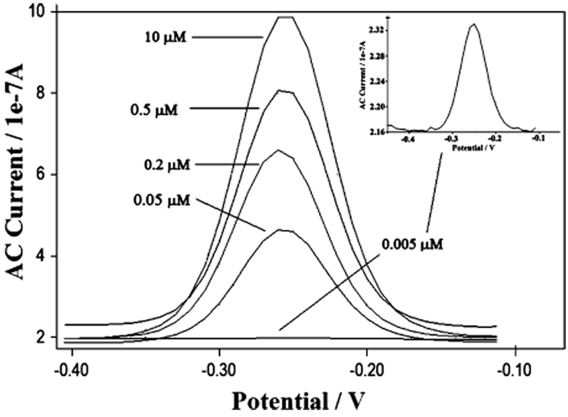
As a test bed for our studies of the effects of molecular crowding on the performance of electrochemical DNA sensors, we employed a signal-off E-DNA sensor directed against 17-bases of the gyrB gene of Salmonella typhimurium.13,24 In the absence of the target DNA, the sensor gives a sharp, well-defined ACV peak at ~260 mV (vs Ag/AgCl), consistent with the formal potential of the MB redox moiety used in this work (Figure 1). Upon hybridization, binding-induced changes in the conformation of the stem-loop probe result in a decrease of the signal. This signal drop (measured as the percentage of signal suppression) is likely to be dependent both on the nature of the molecular packing of probe DNA on the electrode surface and on the nature of the target DNA. The first effect was studied by fabricating DNA sensors with different probe DNA densities on the electrode surface and will be discussed in the following two paragraphs. The second effect was instead verified by employing DNA targets with different lengths, some of which contained bulky, internally hybridized loop structures and three base mismatches. For the sake of clarity, a brief description of the targets (Table 1) together with a simplified scheme of the reaction (Table 2 and Table 3) are illustrated.
Figure 1.
AC voltammograms obtained over a range of probe densities. The probe DNA concentrations used during sensor fabrication are indicated.
Table 1.
Probe and Target Sequences
| DNA | sequencea | Number of bases | description |
|---|---|---|---|
| probe | 5′-HS–(CH2)6–GCAGTATCTTCTATTTCTCCACACTGC–MB-3′ | 27 | probe modified with MB |
| ST-25 | 5′-GTG GAG AAA TAG AAG AT-3′ | 17 | complementary target with 17 bases |
| ST-25-3M1 | 5′-GTG GTG AATTAG ATG AT-3′ | 17 | three separated mismatches |
| ST-25-3M2 | 5′-GTG GAG TTTTAG AAG AT-3′ | 17 | three contiguous mismatches |
| FC-22 | 5′-GCAGTGTG GAG AAATAG AAG AT-3′ | 22 | complementary target with 22 bases |
| FC-27 | 5′-GCAGTGTG GAG AAA TAG AAG AT ACTGC-3′ | 27 | complementary target with 27 bases |
| ML-28 | 5′-GCGTTTTTCGC GTG GAG AAA TAG AAG AT-3′ | 28 | target complementary with 17 bases and an 11-base tail forming a loop |
| ML-38 | 5′-GCGTTTTTCGC GCAGT GTG GAG AAA TAG AAG AT ACTGC-3′ | 38 | target complementary with 27 bases and an 11-base tail forming a loop |
Underlined bases are those different from the normal target so they indicate mismatches and elongation of the target. Bases in italic type are designed to form a structured loop.
Table 2.
Signal Suppression (%) Obtained with Complementary and Mismatch Targets
| Data target |
ST-25 | ST-25-3M2 | ST-25-3M1 |
|---|---|---|---|
| binding schemea |
|||
| high densityb |
71 ± 1 | 59 ± 2 | 61 ± 2 |
| medium density |
31 ± 2 | 26 ± 3 | 26 ± 3 |
| low density |
42 ± 3 | 35 ± 2 | 33 ± 3 |
Labels identify the position of the mismatches. See Table 1 for sequences.
Percent values of signal suppression as a result of target hybridization are the average and standard deviation of measurements performed with four independent sensors.
Table 3.
Signal Suppression (%) Obtained with Longer and Bulkier Targets.
| Data target |
ST-25 | FC-22 | FC-27 | ML-28 | ML-38 |
|---|---|---|---|---|---|
| binding schemea |
|||||
| high densityb |
71 ± 1 | 83 ± 1 | 88 ± 1 | 72 ± 1 | 85 ± 2c |
| medium density |
31 ± 2 | 67 ± 7 | 84 ± 3 | 46 ± 3 | 97 ± 3 |
| low density |
42 ± 3 | 71 ± 4 | 76 ± 3 | 57 ± 4 | 78 ± 4 |
See Table 1 for sequences.
Percent values of signal suppression as a result of target hybridization are the average and standard deviation of measurements performed with four independent sensors.
After the 5 h equilibration time employed here, the signal suppression is not complete. All other measurements reflect equilibrated sensors.
Controlling Probe Surface Density
Knowledge of the extent to which probe density affects the E-DNA signaling and equilibration time would provide a general tool for the optimization of other similar sensing platforms (e.g., refs 13–15) and may provide insight into the details of the sensing mechanism.
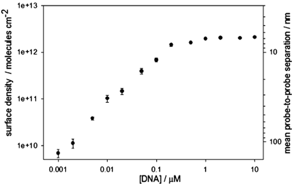
In order to undertake such studies, we have controlled probe density by changing the concentration of probe DNA employed during sensor fabrication. Using this approach, we can readily and reproducibly fabricate E-DNA electrodes with probe densities ranging from 3.9 × 10¹⁰ to 2.1 × 10¹² molecules/cm2 (corresponding to packing of 6.5 × 10⁻¹⁴ to 3.5 × 10⁻¹² mol/cm2) by employing probe DNA concentrations of 0.005 to 5 µM during fabrication (Figure 1 and Figure 2). Attempts to fabricate sensors with lower probe densities fail to produce stable, active films, and no electrochemical signal was detected (data not shown). Indeed, even slightly higher probe densities (1.0 × 10¹⁰ and 2.1 × 10¹⁰ molecules/cm2, fabricated at concentrations of 0.001 and 0.002 µM, respectively) produce poorly defined and poorly reproducible peak currents (relative standard deviation (RSD) = 20%, n = 3), perhaps due to the presence of contaminants and the reducing agent TCEP, which may become more important at low probe concentrations.39 In contrast, probe densities above 3.9 × 10¹⁰ molecules/cm2 (fabricated using probe concentrations of 0.005 µM or higher) give rise to well-defined, reproducible peak currents (all RSD < 7%). The observed probe density increases monotonically with increasing probe concentration until a density of 2.1 × 10¹² molecules/cm2 is obtained using a fabrication concentration of 0.5 µM (Figure 2). Above this concentration, no further increases in probe density are observed.
Figure 2.
We can control probe surface density by varying the concentration of probe DNA employed during sensor fabrication. Shown is the relationship between probe DNA concentration and the final probe density. Values represent the average and standard deviation of measurements conducted with three independently fabricated sensors.
Probe Density Effects on Signaling, Specificity, and Equilibration Time
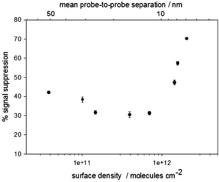
Previous studies using linear DNA probes suggest that the hybridization efficiency of surface-attached DNA molecules decreases monotonically with increasing probe density.5,29–36 The probe density dependence of E-DNA signaling is more complex. For example, we find that the highest probe densities we investigated (~2.1 × 10¹² molecules/cm2) produce the largest signal suppression (~71% at our test target concentration) (Figure 3 and Figure 4, Table 4). As probe density is reduced, the observed signal suppression decreases before reaching a plateau value of ~41% at 3.9 × 10¹⁰ molecules/cm2. Of note, an approximately 3-fold change in the probe density (from 2.1 × 10¹² to 6.6 × 10¹¹ molecules/cm2) gives rise to a 2.5-fold increase in signal suppression. Almost complete regeneration (> 97% recovery of initial signal) is observed with medium- and high-density sensors. In contrast, low-density sensors exhibit only 88% recovery, presumably due to the poorer stability of the probe DNA monolayer (Table 4).
Figure 3.
E-DNA signal suppression is strongly dependent on probe density. At high probe densities, the observed signal suppression decreases monotonically with decreasing density until approximately leveling off at a mean probe separation approximating the ~9.2 nm length of the hybridized probe—target duplex. Shown is the dependence observed at 200 nM target DNA (ST-25). Values represent the average and standard deviation of measurements conducted with three independent sensors at each surface density.
Figure 4.
Representative ACVs illustrating the dependence of signal suppression (after hybridization with target ST-25) on probe surface density.
Table 4.
Summary of E-DNA Sensor Performance
| sensor | probe DNA concentration used during sensor fabrication (µ M) |
probe density (molecules/cm2) |
mean probe-to- probe separation (nm) |
ACV ip (A) |
signal suppression with ST-25 (%) |
detection limita (nM) |
selectivity ratiob |
average regenerationc (%) |
|---|---|---|---|---|---|---|---|---|
| high density | 5 | 2.1 × 10¹² | 6.3 | 7.3 × 10⁻⁷ | 71 ± 1 | 10 | 1.18 | 98 |
| medium density | 0.1 | 6.6 × 10¹¹ | 12.6 | 2.9 × 10⁻⁷ | 31 ± 2 | 10 | 1.19 | 97 |
| low density | 0.005 | 3.9 × 10¹⁰ | 50.9 | 1.6 × 10⁻⁸ | 42 ± 3 | 1.23 | 88 |
Detection limit given is the concentration of ST-25 producing 10% signal suppression.
Ratio between the signal suppression obtained with the complementary target (ST-25) and a mismatched target (ST-25-3M1).
Signal recovery obtained after 10 measurement/wash cycles.
The extent to which probe density modulates signal suppression raises the parallel question of whether the specificity and response time of the E-DNA sensor are also sensitive to this parameter. To address these questions, we have characterized low-, medium-, and high-density E-DNA sensors (obtained using probe DNA concentrations of 0.005, 0.1, and 5 µM, respectively, during sensor fabrication). The probe densities of these sensors, approximately 3.9 × 10¹⁰, 6.6 × 10¹¹, and 2.1 × 10¹² molecules/cm2, respectively correspond to mean probe-to-probe distances of approximately 50.9, 12.6, and 6.3 nm (Table 4). The length of a 27 base pair probe/target duplex is 9.2 nm, suggesting that these densities range from relatively crowed to relatively sparse (assuming that the DNA probes are equally spaced5,30).
We have tested the effect of probe density on sensor specificity using two partially mismatched targets. The first mismatched target, ST-25-3M1, contains three T–T mismatches dispersed throughout the 17-base recognition element (see Table 1). The second, ST-25-3M2, contains three consecutive T–T mismatches near the center of the 17-base recognition element. The ratios of the suppression obtained with the fully complementary target to that observed with mismatched targets provide a measure of the sensor specificity. We find that these ratios are indistinguishable among the three probe densities we have explored in detail, indicating that E-DNA specificity is not a strong function of this parameter. All three sensors similarly fail to discriminate between the two different three-base mismatched targets we have studied (Table 2).
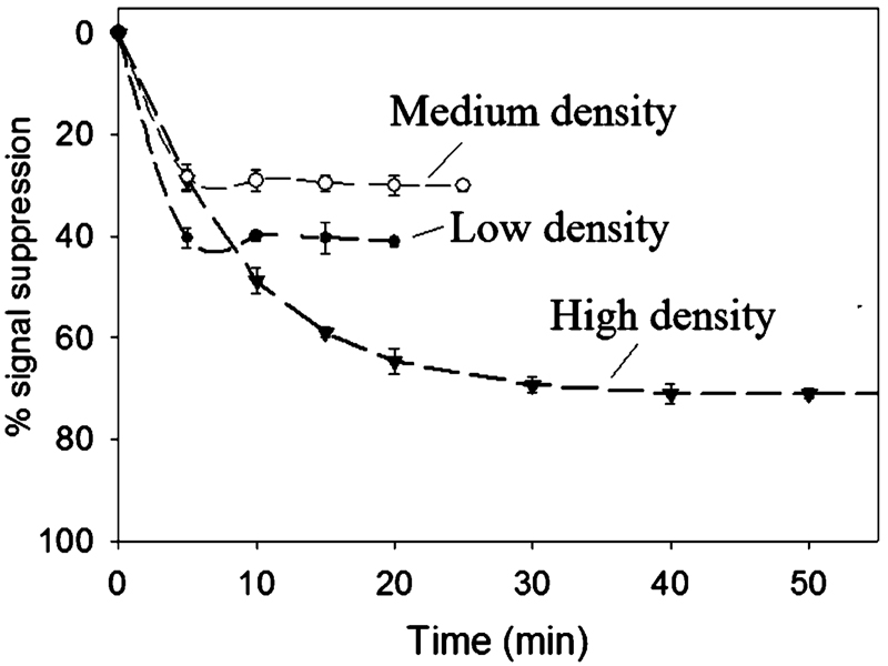
Although signal suppression is optimal at higher probe densities, the equilibration times of theses sensors are increased significantly. For example, the equilibration time constants we observed for high-density sensors (~40 min) are 2 to 8 times longer than the equilibration time constants of medium- and low-density sensors, respectively (Figure 5). We believe this difference arises due to the accessibility of the target sequence to the DNA probe, as has been demonstrated previously.5,29 High-density sensors are characterized by a relatively densely packed probe layer, which likely hinders target accessibility and limits the rate of target—probe hybridization.
Figure 5.
Sensor equilibration time is also dependent on probe density. Shown is the response of three representative sensors to the presence of 200 nM target DNA (ST-25).
Effects of Target Length and Bulk on Signal Suppression
The above results suggest that molecular crowding plays a significant role in defining the response of the E-DNA sensor. This, in turn, suggests that the size and/or structure of the target might also impact signaling. To explore this question, we have investigated targets of varying lengths and targets that adopt bulky secondary structures.
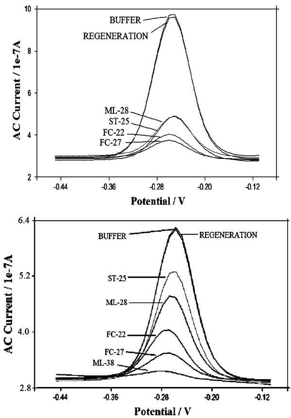
Longer targets produce greater signal suppression (Figure 6). For all the three investigated probe densities, signal suppression increases monotonically as the target is extended from 17 to 27 bases (Table 3). Of note, however, this effect is more prominent at lower surface densities and almost disappears for the highest density sensor, whereas for the high-density sensor we observe only a 19% increase in suppression upon lengthening the target by 10 bases, and the medium- and low-density sensors exhibit 63% and 45% increases, respectively.
Figure 6.
Representative ACVs obtained with high- (top) and medium-density (bottom) sensors indicate that lower-density sensors are better able to discriminate between targets of different size. Refer to Table 1 and Table 2 for DNA target sequences.
We have also investigated the detection of sequences containing internally hybridized loops that increase the steric bulk of the target. These targets, ML-28 and ML-38, hybridize to 17 and 27 bases in the probe sequence, respectively. Both also contain an 11-base tail likely to form a bulky loop structure (see Table 1). The shorter of the two, ML28, increases the signal suppression of low and medium probe density sensors (over the suppression observed with the equivalent linear target ST-25). It does not, however, produce any significant change in the signal suppression of high-density sensors (Table 3). The longer target, ML-38, produces extremely high signal suppression at low and medium probe densities (up to 97%). For the high-density sensor, a direct comparison with the linear target is not possible due to the fact that the hybridization rate for this sensor/target pair is extremely slow: even after 5 h of equilibration, the signal suppression observed (87%) is not complete, probably due to a strong limitation of the hybridization kinetic due to both the highly packed DNA probe surface and the steric hindrance of the target DNA. Of note, the targets FC-27 and ML-38 form continuous double-stranded elements spanning from the MB to the surface of the electrode (Table 1), an effect that might be expected to facilitate electron transfer.7,12 We do not, however, observe any evidence of such facilitation.
Effect of ACV Frequency on Signal Suppression
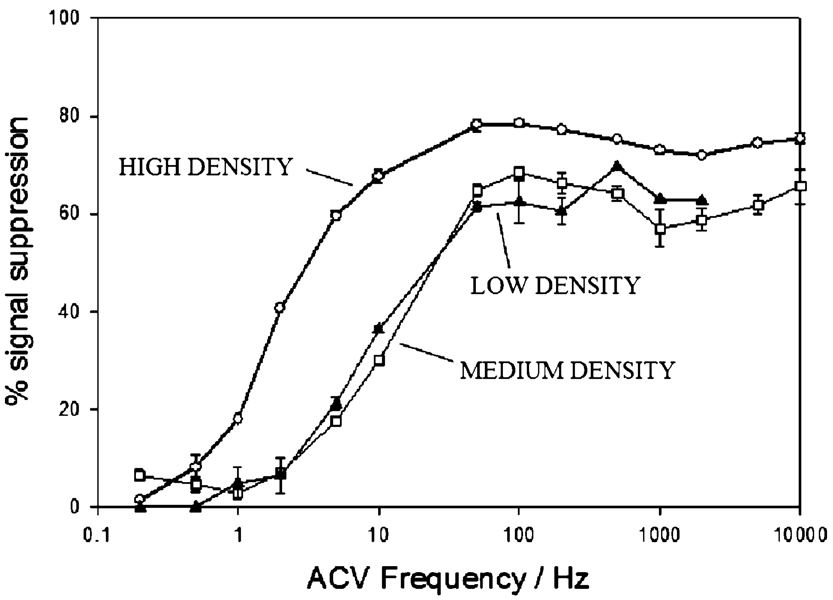
The effect of both probe DNA surface density on sensor specificity and the target length on the sensor response suggests that signal suppression is related to molecular crowding. This, in turn, suggests that the rate at which the terminal redox moiety collides with the electrode surface may play an important role in E-DNA signaling (see ref 37 and discussion below). In order to investigate this in more detail, we studied the ACV frequency dependence of E-DNA signal suppression. At low frequencies, we cannot observe any significant signal suppression (Figure 7), presumably because the collision rates of both the unhybridized and hybridized probes are rapid enough to ensure efficient electron transfer. The signal suppression of the high-density sensor rises dramatically as the frequency is increased above 1 Hz, until it plateaus at ~50 Hz. The medium- and low-density sensors exhibit similar behavior, except that the rise and plateau occurs at slightly higher frequencies.
Figure 7.
E-DNA signal suppression is eliminated at low ACV frequencies. This presumably occurs when the ACV frequency falls below the rate at which the redox moiety of the probe—target duplex collides with the electrode; under these conditions, electron transfer is efficient from both free and bound probes. As the ACV frequency increases, it presumably surpasses the collision rate of the bound probe, reducing transfer efficiency and producing a large, hybridization-linked reduction in the sensing current. Consistent with this argument, the frequency at which this transition occurs is higher for lower density sensors, presumably because reduced probe densities lead to higher collision rates for the probe—target duplex. Shown are the signal suppressions achieved at 200 nM of the target ST-25.
Electron-Transfer Rate Measurements
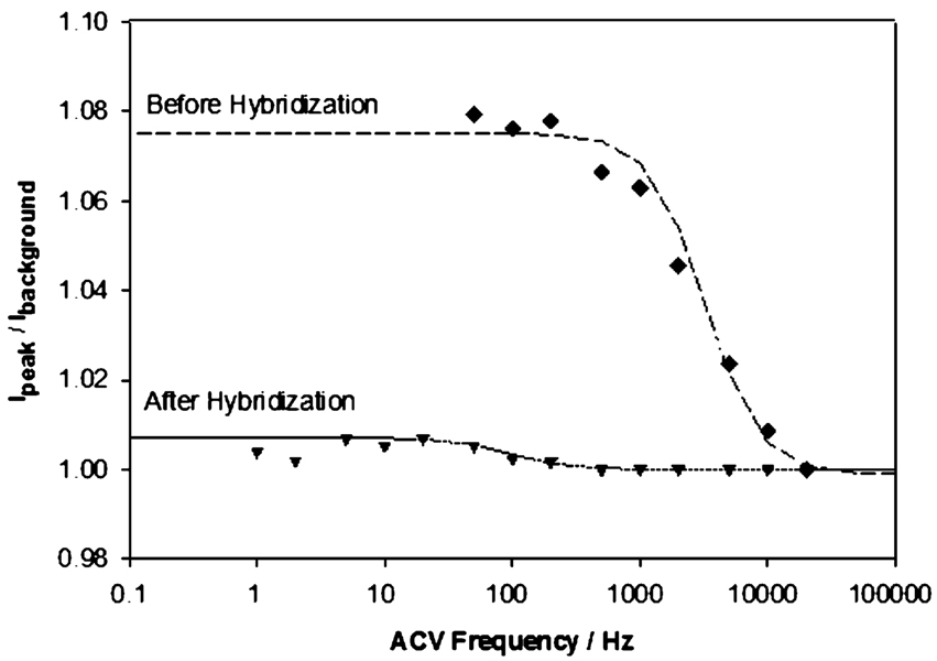
The above results suggest that the electron-transfer rate may depend on the conformation of the DNA, with stem-loop DNA supporting a high transfer rate (limited by the intrinsic electron-transfer rate of the redox moiety) and the target–probe duplex supporting only a slow transfer rate (limited by the rate of collisions with the electrode). In order to test this hypothesis, we first attempted to measure electron-transfer rates in the presence and absence of target using the MB-modified probes employed throughout this study. Unfortunately, however, these probes produce poor baselines at low AC frequencies (data not shown), which precludes the determination of electron-transfer rates. Ferrocene-modified probes, in contrast, exhibit improved baselines and a more easily modeled single electron-transfer reaction (versus the two electron, one proton redox reaction of MB), allowing us to estimate electron-transfer rates for ferrocene-modified probes from plots of the ratio of the peak current to the background current (Figure 8). A dramatic change in the slope of these plots is observed as the AC frequency is increased and the electron-transfer rate is no longer rapid enough to keep pace with the oscillating applied potential. Using this approach we find that, for a low-density sensor, electron-transfer slows by an order of magnitude (from ~20 000 to ~2000 s−1) upon target binding, presumably reflecting the collision-limited transfer rate of the hybridized probe—target duplex. In contrast, the observed transfer rate for high-density sensors, ~20 000 s−1, remains unchanged upon hybridization (data not shown). This presumably occurs because, under these conditions, transfer from the hybridized probe—target duplex is so slow that we only observe transfer from the small, residual population of unhybridized probes.
Figure 8.
A significant reduction in electron-transfer rate is observed upon hybridization for low-density sensors (probe density ~ 3.9 × 10¹⁰ molecules cm−2). A plot of the ratio of peak to background currents versus AC frequency exhibits a dramatic change in slope when electron transfer can no longer respond to the rapidly oscillating applied potential. This presumably reflects a transition from electron transfer limited by the intrinsic transfer rate of the redox moiety (here, ferrocene) to transfer limited by the (much slower) rate at which the end of the probe—target duplex collides with the electrode. Shown are data collected from a single electrode; measurements from multiple (>6) electrodes are highly correlated, exhibiting less than a 10% standard deviation.
Discussion
Here we have shown that the density of probe DNA strands on the electrode surface significantly affects the performance of the electrochemical E-DNA sensor. We find that the highest signal suppression is obtained with the highest probe density investigated, despite the fact that hybridization efficiency may be reduced as probe density increases.5,29–36 In contrast to the improved signal suppression observed at the highest probe densities, we find that sensor equilibration time slows monotonically with increasing density. Finally, we find that the specificity of hybridization is not significantly affected by changes in probe density.
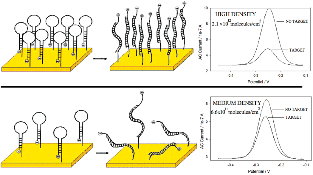
The results presented here provide insight into the mechanism of E-DNA signaling. It has previously been speculated that, upon hybridization, the electrochemical signal generated in E-DNA-like sensors results from an “electron tunneling effect” along the double helix, so that the signal suppression observed arises solely due to the increased tunneling distance between the redox moiety and the electrode.13–15 The results obtained in this work, however, suggest an alternative mechanism for the observed signaling: hybridization changes the rate at which the redox moiety collides with the electrode surface. The formation of the stem induces efficient electron transfer at both low and high probe densities. At low probe densities, however, the signal suppression observed upon hybridization is limited because even hybridized probe DNA can, on occasion, collide with the electrode surface and transfer electrons (Figure 9, see also ref 37). At high probe densities, in contrast, the steric bulk of the closely packed DNA probes precludes these collisions, leading to higher signal suppression despite presumably lower hybridization efficiency.5,29–37 This hypothesis is further supported by the observation that, at low probe densities, targets containing bulky loop structures produce greater suppression than their equivalent linear targets (despite presumably similar hybridization thermodynamics). For our highest-density sensors, however, this effect is mitigated. We assume this occurs when increasing probe density reduces the collision rate of the target—probe duplex so much that increasing the steric bulk of the target does not lead to any further suppression. Consistent with these speculations, E-DNA signal suppression decreases monotonically with decreasing probe density until leveling off at a mean probe separation corresponding to the ~9.2 nm length of the hybridized probe—target duplex (Figure 3).
Figure 9.
The results presented here suggest that E-DNA signaling arises, at least in part, from hybridization-induced changes in the rate with which the terminal redox moiety collides with the electrode. For example, the largest signal suppression is observed for high-density sensors, presumably because the densely packed probe layer prevents collisions after target hybridization. Consistent with this, the mean distance between the probes on a high-density sensor (i.e., 6.3 nm) is less than the length of the fully hybridized probe DNA (~9.2 nm). Poorer signal suppression is observed for lower-density sensors (in which the mean probe separation is greater than the length of the probe, 12.6 nm), presumably because hybridization does not abolish such collisions. For the same reason, lower density sensors are more strongly affected by the size and bulk of the target.
Anne and Demaille reported that the intrinsic bending elasticity of DNA controls the dynamics of electron transport in molecular layers comprised of surface-attached, redox-modified DNA.40 Our studies of the ACV frequency dependence of E-DNA signaling support this claim and provide further evidence for the collisional signaling mechanism. Signal suppression is alleviated at low ACV frequencies, presumably because electron transfer is efficient from both the free and bound probe when the ACV frequency falls below the rate at which even the redox moiety of the bound probe collides with the electrode. As the ACV frequency increases above the slower collision rate of the bound probe, transfer efficiency from this state is reduced, producing a large, hybridization-linked reduction in the sensing current. Consistent with this argument, the frequencies at which this transition occurs are higher for lower-density sensors, presumably because reduced probe densities leads to higher collision rates for the probe—target duplex.
The results presented here are likely relevant to the signaling mechanisms of a range of conformation-linked biosensors, including surface-bound molecular beacons17–20 and the aptamer-based E-AB sensing platform.13–15,27,41,43,44 The latter class of sensors, directly analogous to the E-DNA sensor, is based on the binding-induced folding of DNA aptamers and has been demonstrated for targets ranging from proteins26,41,42 to small molecules27 and inorganic ions.43,44 The results presented here suggest that careful optimization of probe density and measurement techniques will be necessary in order to achieve maximum performance across this broad and increasingly important class of sensors.
Acknowledgment
The authors acknowledge Prof. C. E. Immoos for assistance in obtaining the ferrocene-modified oligonucleotide and Michael S. C. Wong for his assistance in the laboratory. The authors also acknowledge the U.S. Army’s Institute for Collaborative Biotechnologies (Contract Number DAAD 19-03-D-0004) and the Center for Nanoscience Innovation for Defense (DMEA 90-02-2-0215) for financial support of this work.
References
- 1.Heller MJ. Annu. Rev. Biomed. Eng. 2002;4:129–153. doi: 10.1146/annurev.bioeng.4.020702.153438. [DOI] [PubMed] [Google Scholar]
- 2.Balakin KV, Korshun VA, Mikhalev II, Maleev GV, Malakhov AD, Prokhorenko IA, Berlin YuA. Biosens. Bioelectron. 1998;13:771–778. doi: 10.1016/s0956-5663(98)00041-4. [DOI] [PubMed] [Google Scholar]
- 3.Cao YWC, Jin RC, Mirkin CA. Science. 2002;297:1536–1540. doi: 10.1126/science.297.5586.1536. [DOI] [PubMed] [Google Scholar]
- 4.Gaylord BS, Heeger AJ, Bazan GC. Proc. Natl. Acad. Sci. U.S.A. 2002;99:10954–10957. doi: 10.1073/pnas.162375999. [DOI] [PMC free article] [PubMed] [Google Scholar]
- 5.Peterson AW, Wolf LK, Georgiadis RM. J. Am. Chem. Soc. 2002;124:14601–14607. doi: 10.1021/ja0279996. [DOI] [PubMed] [Google Scholar]
- 6.Ahn S, Walt DR. Anal. Chem. 2005;77(15):5041–5047. doi: 10.1021/ac0505270. [DOI] [PubMed] [Google Scholar]
- 7.Kelley SO, Barton JK, Jackson NM, Hill MG. Bioconjugate Chem. 1997;8:31–37. doi: 10.1021/bc960070o. [DOI] [PubMed] [Google Scholar]
- 8.Cooper MA, Dultsev FN, Minson T, Ostanin VP, Abell C, Klenerman D. Nat. Biotechnol. 2001;19:833–837. doi: 10.1038/nbt0901-833. [DOI] [PubMed] [Google Scholar]
- 9.Endo T, Kerman K, Nagatani N, Takamura Y, Tamiya E. Anal. Chem. 2005;77(21):6976–6984. doi: 10.1021/ac0513459. [DOI] [PubMed] [Google Scholar]
- 10.Patolsky F, Lichtenstein A, Willner I. J. Am. Chem. Soc. 2000;122(2):418–419. [Google Scholar]
- 11.Park SJ, Taton TA, Mirkin CA. Science. 2002;295:1503–1506. doi: 10.1126/science.1067003. [DOI] [PubMed] [Google Scholar]
- 12.Boon EM, Ceres DM, Drummond TG, Hill MG, Barton JK. Nat. Biotechnol. 2000;18:1096–1100. doi: 10.1038/80301. [DOI] [PubMed] [Google Scholar]
- 13.Fan C, Plaxco KW, Heeger AJ. Proc. Natl. Acad. Sci. U.S.A. 2003;100:9134–9137. doi: 10.1073/pnas.1633515100. [DOI] [PMC free article] [PubMed] [Google Scholar]
- 14.Immoos CE, Lee SJ, Grinstaff MW. J. Am. Chem. Soc. 2004;126:10814–10815. doi: 10.1021/ja046634d. [DOI] [PubMed] [Google Scholar]
- 15.Immoos CE, Lee SJ, Grinstaff MW. Chem Bio Chem. 2004;5:1100–1104. doi: 10.1002/cbic.200400045. [DOI] [PubMed] [Google Scholar]
- 16.Mao T, Luo C, Ouyang Q. Nucleic Acids Res. 2003;31:108–172. doi: 10.1093/nar/gng108. [DOI] [PMC free article] [PubMed] [Google Scholar]
- 17.Du H, Disney MD, Miller BL, Krauss TD. J. Am. Chem. Soc. 2003;125:4012–4013. doi: 10.1021/ja0290781. [DOI] [PubMed] [Google Scholar]
- 18.Du H, Strohsahl CM, Camera J, Miller BL, Krauss TD. J. Am. Chem. Soc. 2005;127:7932–7940. doi: 10.1021/ja042482a. [DOI] [PubMed] [Google Scholar]
- 19.Wang H, Li J, Liu H, Liu Q, Mei Q, Wang Y, Zhu J, He N, Lu Z. Nucleic Acids Res. 2002;30:e61. doi: 10.1093/nar/gnf061. [DOI] [PMC free article] [PubMed] [Google Scholar]
- 20.Ramachandran A, Flinchbauch J, Ayoubi P, Olah GA, Malayer JR. Biosens. Bioelectron. 2004;19:727–736. doi: 10.1016/j.bios.2003.08.004. [DOI] [PubMed] [Google Scholar]
- 21.Palecek E. Trends Biotechnol. 2004;22:55–58. doi: 10.1016/j.tibtech.2003.11.009. [DOI] [PubMed] [Google Scholar]
- 22.Thorp HH. Trends Biotechnol. 2003;21(12):522–524. doi: 10.1016/j.tibtech.2003.10.003. [DOI] [PubMed] [Google Scholar]
- 23.Lubin AA, Lai RY, Baker BR, Heeger AJ, Plaxco KW. Anal. Chem. 2006;78(16):5671–5677. doi: 10.1021/ac0601819. [DOI] [PubMed] [Google Scholar]
- 24.Lai RY, Lagally ET, Lee S-H, Soh HT, Plaxco KW, Heeger AJ. Proc. Natl. Acad. Sci. U.S.A. 2006;103:4017–4021. doi: 10.1073/pnas.0511325103. [DOI] [PMC free article] [PubMed] [Google Scholar]
- 25.Lai RY, Seferos DS, Heeger AJ, Bazan GC, Plaxco KW. Langmuir. 2006;22:10796–10800. doi: 10.1021/la0611817. [DOI] [PubMed] [Google Scholar]
- 26.Xiao Y, Piorek BD, Plaxco KW, Heeger AJ. J. Am. Chem. Soc. 2005;127:17990–17991. doi: 10.1021/ja056555h. [DOI] [PubMed] [Google Scholar]
- 27.Baker BR, Lai RY, Wood MS, Doctor EH, Heeger AJ, Plaxco KW. J. Am. Chem. Soc. 2006;128:3138–3139. doi: 10.1021/ja056957p. [DOI] [PubMed] [Google Scholar]
- 28.Lai RY, Lee S-H, Soh HT, Plaxco KW, Heeger AJ. Langmuir. 2006;22:1932–1936. doi: 10.1021/la052132h. [DOI] [PubMed] [Google Scholar]
- 29.Peterson AW, Heaton RJ, Georgiadis RM. Nucleic Acids Res. 2001;29:5163–5168. doi: 10.1093/nar/29.24.5163. [DOI] [PMC free article] [PubMed] [Google Scholar]
- 30.Levicky R, Herne TM, Tarlov MJ, Satija SK. J. Am. Chem. Soc. 1998;120:9787–9792. [Google Scholar]
- 31.Southern E, Mir K, Shchepinov M. Nat. Genet. 1999;21:5–9. doi: 10.1038/4429. [DOI] [PubMed] [Google Scholar]
- 32.Steel AB, Herne TM, Tarlov MJ. Anal. Chem. 1998;70:4670–4677. doi: 10.1021/ac980037q. [DOI] [PubMed] [Google Scholar]
- 33.Huang E, Satjapipat M, Han SB, Zhou FM. Langmuir. 2001;17:6188–6190. [Google Scholar]
- 34.O’Connor SD, Olsen GT, Creager SE. J. Electroanal. Chem. 1999;466:197–202. [Google Scholar]
- 35.Lee C-Y, Gong P, Harbers GM, Grainger DW, Castner DG, Gamble LJ. Anal. Chem. 2006;78(10):3316–3325. doi: 10.1021/ac052137j. [DOI] [PubMed] [Google Scholar]
- 36.Gong P, Lee C-Y, Gamble LJ, Castner DG, Grainger DW. Anal. Chem. 2006;78(10):3326–3334. doi: 10.1021/ac052137j. [DOI] [PMC free article] [PubMed] [Google Scholar]
- 37.Creager SE, Wooster TT. Anal. Chem. 1998;70:4257–4263. [Google Scholar]
- 38.Sumner JJ, Weber KS, Hockett LA, Creager SE. J. Phys. Chem. B. 2000;104:7449–7459. [Google Scholar]
- 39.Lee C-Y, Canavan HE, Gamble LJ, Castner DJ. Langmuir. 2005;21:5134–5141. doi: 10.1021/la0472302. [DOI] [PubMed] [Google Scholar]
- 40.Anne A, Demaille C. J. Am. Chem. Soc. 2006;128:542–557. doi: 10.1021/ja055112a. [DOI] [PubMed] [Google Scholar]
- 41.Radi A-E, Acero Sanchez JL, Baldrich E, O’Sullivan CK. J. Am. Chem. Soc. 2006;128(1):117–124. doi: 10.1021/ja053121d. [DOI] [PubMed] [Google Scholar]
- 42.Lai R, Plaxco KW, Heeger AJ. Anal. Chem. 2007;79(1):229–233. doi: 10.1021/ac061592s. [DOI] [PubMed] [Google Scholar]
- 43.Xiao Y, Rowe AA, Plaxco KW. J. Am. Chem. Soc. 2007;129:262–263. doi: 10.1021/ja067278x. [DOI] [PubMed] [Google Scholar]
- 44.Radi AE, O’Sullivan CK. Chem. Commun. 2006;32:3432–3434. doi: 10.1039/b606804a. [DOI] [PubMed] [Google Scholar]


