Abstract
Many next-generation adaptive optics (AO) systems for vision will have two deformable mirrors (DMs) instead of one: a high-stroke, low-resolution mirror (the woofer) and a low-stroke, high-resolution mirror (the tweeter). We developed a zonal wavefront-control algorithm and validated it using simulations. Rather than separating the woofer and tweeter corrections into two independent control processes or using a modal decomposition, the algorithm we proposed uses wavefront slope measurements from a single Shack–Hartmann wavefront sensor to generate control signals for both deformable mirrors within a single zonal control. A Lagrange multiplier is chosen to integrate two DMs into a single-DM wavefront control, and a damped least-squares control is employed to suppress the correlation between the two DMs.
In many wavefront-control applications, there is a need for both high-amplitude wavefront corrections for low-order aberrations and low amplitude corrections for high-order aberrations. One approach to meeting this need is to use two deformable mirrors (DMs): a high-stroke woofer DM and a low-stroke tweeter DM. The woofer-tweeter approach has been studied in adaptive optics (AO) control in wavefront turbulence scintillation and in astronomy [1–5], as well as in retinal imaging [6]. In retinal imaging with an AO scanning laser ophthalmoscope (AOSLO), a dual-DM approach is desirable owing to the large individual differences in defocus and astigmatism in humans and to large dynamic changes in focus (accommodation). In previous work the dual-DM correction was treated sequentially [6]; first the woofer was optimized and then the tweeter.
In this Letter we present a real-time zonal control algorithm for implementation of a woofer–tweeter dual-DM AOSLO system for in-vivo human retinal imaging with a 140 actuator Boston micromachine (BMC) DM (maximum stroke 2.5 μm) and a 52 actuator Mirao magnetic DM (maximum stroke 50 μm). Wavefront errors are measured by a Shack-Hartmann sensor. The high-stroke Mirao DM is the woofer for correcting the low-order aberrations, and the low-stroke BMC DM is the tweeter for correcting the high-order aberrations. In retinal imaging the ability to rapidly focus at different locations and depths in the retina is desired, so one goal of the algorithm is to provide simultaneous control rather than optimizing the mirrors sequentially and independently. To do this, the algorithm needs to sort the wavefront aberrations into two groups, one for the woofer correction and one for the tweeter correction in real time.
For initial modeling we assume that the DM1 mirror is the woofer DM and the DM2 mirror is the tweeter DM. Given wavefront slope (the first derivative of wavefront) measurements S, the problem of wavefront control with a woofer–tweeter system can be expressed as the requirement to determine actuator stroke vectors X for DM1 and Y for DM2, where DM1 and DM2 are coupled with a single wavefront sensor (WFS) via influence matrices A and B.
Mathematically we can construct a single “imaginary” deformable mirror from the two mirrors that are physically independent but optically conjugated. The task is to form a new influence matrix for the imaginary DM, with which the imaginary DM will naturally correct both the low-order and high-order wavefront aberrations. To integrate the two DMs as one, a Lagrange multiplier λ is introduced to match the influence matrix B of DM2 with the influence matrix A of DM1. The Lagrange multiplier is simply a weighting factor between the two DM controls [7]. To describe the wavefront-control problem, a cost function (or merit function) can be defined as
| (1) |
which is a measure of the residual wavefront error in a least-squares sense. In this equation, S is a vector of Shack–Hartmann sensor measurements. Our goal is to correct the wavefront such that the cost function is minimized, which requires ∂ψ/∂X=0 and ∂ψ/∂Y = 0. Therefore, we have
| (2) |
In matrix form, Eq. (2) can be written as
| (3) |
where C = [A λB] is the influence matrix of the imaginary DM, and P = [XT YT]T is the actuator stroke vector of the imaginary DM. In this way a dual-DM AO control becomes a single-DM AO control.
Because DM1 and DM2 share the same wavefront sensor and contribute to the same wavefront correction, the actuators between DM1 and DM2 are not independent, and therefore matrices A and B are either rank deficient or ill conditioned. For instance, DM1 and DM2 could generate wavefront corrections with opposite signs to yield a very small total wavefront correction. For our proposed configuration we calculated that matrix ATA has at least seven eigenvalues close to zero, and matrix BTB has eight close and four that are zero. In an optimal situation, matrix CTC has at least 16 eigenvalues that are close to zero and four eigenvalues that are zero. Therefore the least-squares solutions to Eq. (3) are not deterministic, and the inverse of the normal matrix does not exist. Singular-value decomposition (SVD) can be employed to obtain a least-squares solution for this problem, but this solution is not necessarily optimal. To suppress the correlation between two DMs, we employ a damped least-squares method, obtaining an iterative solution. The damped least-squares method, also referred to as the Tikhonov regularization method in solving linear ill-posed problems, has many applications, such as in optical design for searching the optimum solution to minimize a cost function [8,9].
Therefore, a damped least-squares solution to this problem can be expressed as
| (4) |
where β1 and β2 are damping parameter matrices, which can be determined empirically.
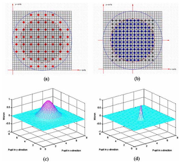
To validate the algorithm, we assume the influence functions of DM1 and DM2 are both Gaussian: one is wider to represent a typical woofer mirror and the other is narrower to represent a tweeter mirror, where the influence function means the mirror surface shape change per unit change of actuator displacement or force. Figures 1(a) and 1(b) show the mapping between the actuators of DM1, DM2, and the lenslet array (25×25); Figures 1(c) and 1(d) show an influence function generated by a unit Gaussian function (standard deviation σ=1 and σ=0.2, respectively) for an actuator on DM1 and DM2, respectively.
Fig. 1.

(Color online) (a) Mapping of the DM1 (Mirao) actuators and lenslet array. (b) Mapping of the DM2 (BMC) actuators and lenslet array. (c) Influence function of a DM1 actuator at (4.25, 4.25) (σ=1, Gaussian). (d) Influence function of a DM2 actuator at point (3.75, 3.25) (σ=0.2, Gaussian).
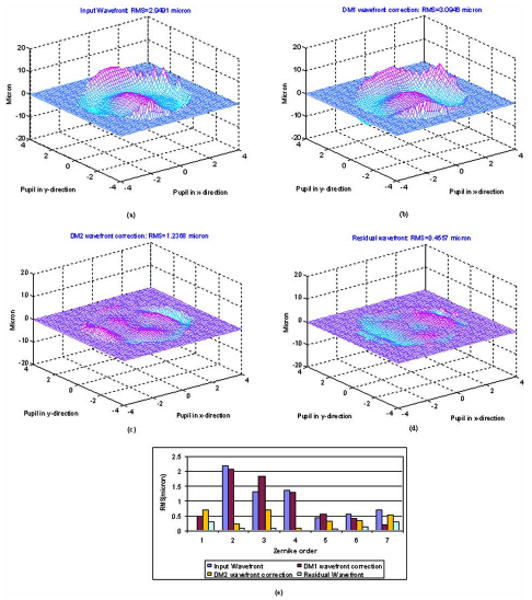
An input wavefront from a human eye is shown in Fig. 2(a) [10], and the wavefront slopes written in vector S were computed. We computed the actuator stroke vectors X and Y for wavefront-error correction using Eq. (4) with λ=1 and the damping factors equal 2. From the actuator stroke vectors X and Y, we estimated the wavefront error corrected by DM1 and the wavefront error corrected by DM2 [Figs. 2(b) and 2(c)] and the residual wavefront error after one iteration [Fig. 2(d)]. Figure 2(e) shows a comparison of the wavefront errors quantified by Zernike order [11]. As expected, most of the wavefront errors are decreased; the low-order aberrations are corrected mainly by DM1, and high-order aberrations are corrected mainly by DM2.
Fig. 2.

(Color online) (a) Input wavefront error map (RMS=2.9491 μm). (b) 3D map of the DM1 wavefront correction (RMS=3.0946 μm). (c) 3D map of the DM2 wavefront correction (RMS= 1.2368 μm). (d) Residual wavefront error map (RMS = 0.4557 μm). (e) Wavefront error comparisons quantified by Zernike order.
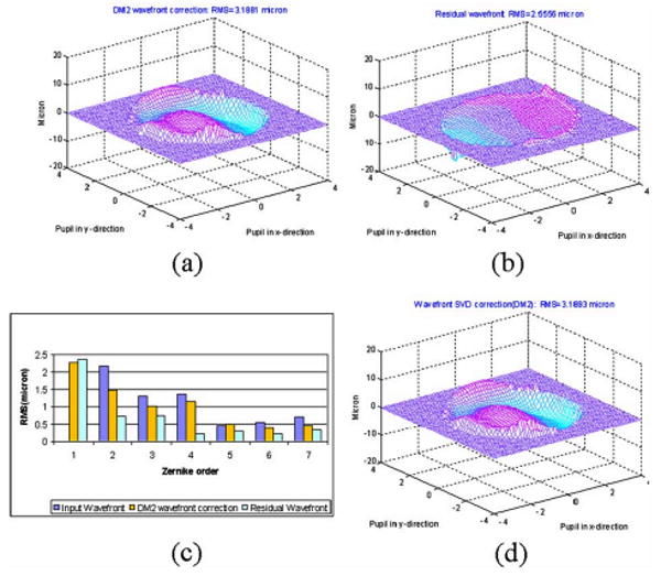
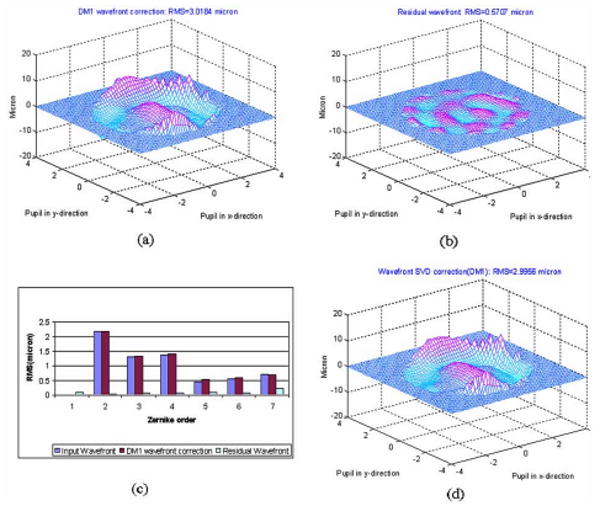
To further validate the proposed algorithm, we set DM1 to flat and used DM2 alone to computationally correct the high-order errors of the input wavefront in Fig. 2 without damping and compared the result to a conventional SVD approach for a single mirror control (Fig. 3). This confirmed that the proposed algorithm when working with a single DM produces equivalent results to the conventional SVD method. Alternatively, we can fix DM2 to flat and correct with DM1, only with similar results (Fig. 4), but now, as expected owing to the wide influence function of the actuators and the low number of actuators, low-order aberrations decreased, but high-order aberrations could not be corrected.
Fig. 3.

(Color online) (a) 3D map of the DM2 wavefront correction (no damping, RMS=3.1881 μm). (b) Residual wavefront error map (RMS = 2.5556 μm). (c) Wavefront error comparisons quantified by Zernike order. (d) Single-DM2 wavefront correction with conventional SVD method (RMS=3.1893 μm).
Fig. 4.

(Color online) (a) 3D map of the (Color on line) DM1 wavefront correction (no damping, RMS=3.0184 μm). (b) Residual wavefront error map (RMS = 0.5707 μm). (c) Wavefront error comparisons quantified by Zernike order. (d) Single-DM1 wavefront correction with conventional SVD method (RMS = 2.9956 μm).
A dual-DM woofer–tweeter AO system with the proposed wavefront control algorithm is shown to have improved performance relative to a single-DM AO system in wavefront-correction accuracy and dynamic range. The proposed algorithm sorts the wavefront aberration into low-order and high-order groups based only on the influence function of the mirrors and assigns them to the woofer–tweeter DMs for correction without performing a modal decomposition of the wavefront errors. By changing the damping factors, the degree of wavefront correction per control step can be varied. When one of the DMs is frozen, the dual-DM wavefront correction is equivalent to a single-DM correction with the conventional SVD method. To test the range of our algorithm we examined the impact of the relative widths of the influence functions with our geometry (Fig. 1). For best control, the widths of the two influence function should differ by approximately a factor of 4 to 5 times. Smaller differences will produce more correlation between the two DMs; however, it is still geometry dependent. For instance, if DM1 and DM2 are identical but their actuators are spatially interleaved, the spatial frequency of the composite wavefront correction will be increased by a factor of with the composite grid at 45 deg rotation in orientation compared with the original DM grids. That is, higher-order wavefront corrections can be achieved by two low-order DMs in optical conjugation if they are integrated together by the proposed algorithm. This approach was first studied by Yang and Liu et al. [12,13], and it may find applications in real systems, because the high-order DMs can be more expensive than several low-order DMs.
As a generalization of the proposed algorithm, a wavefront-control equation for multiple optically conjugate DMs can be written as
| (5) |
where λi(i=1,2, … t) are the Lagrange multipliers for the DMs in tandem with corresponding influence matrices Ai(i=1,2, …t), and Fi(i =1,2, …t) are the actuator vectors of the DMs. With Eq. (5) we can integrate more stroke-limited DMs into an imaginary one to extend the stroke capability and increase spatial resolution of wavefront correction.
Acknowledgments
This work was supported by National Institutes of Health NIH EY04395 and NIH EY14375.
References
- 1.Conan R, Bradley C, Hampton P, Keskin O, Hilton A, Blain C. Appl Opt. 2007;46:4329. doi: 10.1364/ao.46.004329. [DOI] [PubMed] [Google Scholar]
- 2.Brennan TJ, Rhoadarmer TA. Proc SPIE; 2006. p. 63060B1. [Google Scholar]
- 3.Barchers JD. J Opt Soc Am A. 2002;19:926. doi: 10.1364/josaa.19.000926. [DOI] [PubMed] [Google Scholar]
- 4.Barchers JD. J Opt Soc Am A. 2002;19:54. doi: 10.1364/josaa.19.000054. [DOI] [PubMed] [Google Scholar]
- 5.Hu S, Xu B, Zhang X, Hou J, Wu J, Jiang W. Appl Opt. 2006;45:2638. doi: 10.1364/ao.45.002638. [DOI] [PubMed] [Google Scholar]
- 6.Chen DC, Jones SM, Silva DA, Olivier SS. J Opt Soc Am A. 2007;24:1305. doi: 10.1364/josaa.24.001305. [DOI] [PubMed] [Google Scholar]
- 7.Zou W. Opt Eng. Vol. 41. Bellingham: 2002. p. 2338. [Google Scholar]
- 8.Su DQ, Wang YN. Acta Astron Sin. 1974;15:51. [Google Scholar]
- 9.Levenberg K. J Appl Math. 1994;2:164. [Google Scholar]
- 10.McLellan JS, Marcos S, Burns SA. Invest Ophthalmol Visual Sci. 2001;42:1390. [PubMed] [Google Scholar]
- 11.Noll RJ. J Opt Soc Am. 1976;66:207. [Google Scholar]
- 12.Yang H, Liu G, Rao C, Zhang W, Jiang W. Chin Opt Lett. 2007;5:435. [Google Scholar]
- 13.Liu G, Yang H, Rao C, Zhang Y, Jiang W. Chin Opt Lett. 2007;5:559. [Google Scholar]


