

Abstract
Extracellular matrix (ECM) scaffolds prepared from different tissue sources or using different methods have been demonstrated to have distinctive effects upon cell adhesion patterns and the ability to support and maintain differentiated phenotypes. It is unknown whether the molecular composition or the ultrastructure of the ECM plays a greater role in determining the phenotype of the cells with which it comes into contact. However, when implanted, the topology and ligand landscape of the material will determine the host molecules that bind and the type and behavior of cells that mediate the host response. Therefore, a comprehensive understanding of surface characteristics is essential in the design of scaffolds for specific clinical applications. The surface characteristics of ECM scaffolds derived from porcine urinary bladder, small intestine, and liver as well as the effects of two commonly used methods of chemical cross-linking upon UBM were investigated. Electron microscopy and time of flight secondary ion mass spectroscopy were used to examine the surface characteristics of the scaffolds. The results show that ECM scaffolds have unique morphologic and structural properties which are dependant on the organ or tissue from which the scaffold is harvested. Furthermore, the results show that the surface characteristics of an ECM scaffold are changed through chemical cross-linking.
1. Introduction
The extracellular matrix (ECM) is composed of the secreted molecules produced by the resident cells of each tissue or organ. Thus, the composition and three-dimensional ultrastructure of the ECM is highly related to cell phenotype and the required functions of the tissue or organ from which it is derived. The exact composition of the ECM is dependant on a number of factors that influence resident cell phenotype including mechanical forces, biochemical milieu, oxygen requirements, pH, and gene expression patterns, among others. The ECM, in turn, influences the phenotype, migration, and proliferation of its resident cells, and serves as a medium for signal transfer between cells [1-4]. For these reasons, the ECM is considered to be in a state of dynamic equilibrium [2] and to play an important role in normal tissue and organ morphogenesis [5].
For these same reasons, biologic scaffolds composed of ECM have been investigated as inductive templates for functional tissue reconstruction in a number of anatomic locations including the lower urinary tract, skin, musculotendinous tissues, dura mater, esophagus and cardiovascular structures in both preclinical animal studies and in human clinical applications [6-16]. ECM scaffolds prepared from different tissue sources or prepared using different methods have been shown to have distinctive effects upon cell adhesion patterns [17-19], the ability to support and maintain a differentiated cell phenotype [1, 20, 21], oxygen diffusivity [22], and water permeability [23, 24]. It is unknown whether the bulk (or average) composition of the ECM, the surface chemistry, or the ultrastructural morphology, especially the surface ultrastructure, plays a greater role in determining the phenotype of the cells with which it contacts.
The process of host remodeling of a biologically derived scaffold is dependant upon the immediate and subsequent events that occur at the surface of the material following in vivo implantation. The surface topography and ligand landscape of the scaffold material will determine the host molecules that bind and the type and behavior of cells that mediate the host response. The production of biologic scaffolds composed of ECM requires the use of processing methods that decellularize and terminally sterilize the material [25]. These methods can affect the composition, ultrastructure, mechanical properties, and surface topography of the resulting scaffold, thus affecting the host response associated with its use [25]. Similarly, chemical cross-linking is a method used in the production of many commercially available ECM scaffolds that may affect the surface characteristics of the resulting material as well as alter the host response following implantation [26, 27]. Therefore a comprehensive understanding of surface characteristics is essential for the design of intelligent scaffolds for specific clinical applications.
Time of flight secondary ion mass spectroscopy (ToF-SIMS) is an analytically sensitive surface technique that can be used to create a detailed mass spectrum of the outermost 10-20 Å of a sample [28]. ToF-SIMS is performed by bombarding the surface of the sample with a beam of primary ions and then measuring the intensities of the individual masses of the positive and negative secondary ions emitted. Analysis of the type and amount of secondary ions generated can provide important information about the material from which they were emitted including the composition, structure, orientation and spatial distribution of the molecules on the surface.
The objectives of the present study were twofold: (1) to determine and compare by SEM and ToF-SIMS the ultrastructure and molecular composition of the various surfaces of extracellular matrix (ECM) scaffolds derived from porcine urinary bladder, small intestine, and liver and (2) to determine the effects of two commonly used methods of chemical cross-linking (carbodiimide and glutaraldehyde) upon the surface characteristics of one of these ECM scaffold materials, specifically urinary bladder derived extracellular matrix.
2. Materials and Methods
2.1 Harvest and preparation of biologic scaffolds composed of ECM
The ECM scaffold materials utilized in this study were prepared by methods previously described [17]. The urinary bladder, small intestine, and liver were harvested from market weight pigs immediately following sacrifice.
2.1.1 Preparation of urinary bladder matrix
Excess adipose tissue and collagenous connective tissue as well as the apex were removed from the urinary bladder using scissors. The bladder was then opened on one side from the neck to the dome region to form a rectangular-shaped sheet. The tunica serosa, tunica muscularis externa, tunica submucosa, and the muscularis mucosa were removed by mechanical delamination, leaving only the basement membrane and tunica propria intact. The remaining tissue was then soaked in deionized (DI) water and represented the layers of the urinary bladder that constituted urinary bladder matrix (UBM) [29].
2.1.2 Preparation of small intestinal submucosa
The jejunum of the small intestine was isolated and the mesentery removed using scissors. The lumen of the isolated segment of intestine was then flushed with running tap water. The intestine was then split longitudinally and mechanically delaminated to remove the luminal portions of the tunica mucosa, including the majority of the lamina propria, and the tunica muscularis externa and serosa. The remaining portions of the tunica submucosa and the tunica mucosa, specifically the muscularis mucosa and stratum compactum, were soaked in DI water and represented the layers of the small intestine that constituted small intestinal submucosa (SIS) [30].
2.1.3 Preparation of liver ECM
The four lobes of the porcine liver were separated using scissors. The liver lobes were allowed to freeze completely at -80°C and were then cut into 5 mm slices using a rotating blade. The liver slices were treated with enzymatic and detergent solutions to remove cellular content. The liver slices were placed in DI water and placed on a shaker for 30 min at room temperature. This process was repeated with clean DI water for a total of three water rinses. The slices were then massaged to hasten the lysis of the hepatocytes and the removal of cell remnants, and were placed in 0.02% trypsin/0.05% EDTA at 37°C for 1 h on a shaker. The slices were rinsed in DI water, and the massaging repeated. The liver slices were then placed back on the shaker at room temperature for 1 h in 3% Triton X-100, followed by a thorough rinse in DI water. Following that the massage was repeated as necessary to remove remaining cellular elements. The slices were then placed in 4% sodium deoxycholic acid for 1 h on a shaker and then rinsed in water. The remaining connective tissue matrix was soaked in DI water and represented the portion of the liver that constituted liver ECM (LECM) [31].
2.1.4 Disinfection, cell lysis, and terminal sterilization of scaffold materials
Following removal of the appropriate tissue layers and bulk cellular contents from the three organs as described above, the remaining tissue was treated with a 0.1% peracetic acid/4% ethanol solution for 2 h at room temperature on a shaker. Traces of peracetic acid were removed and the pH was returned to approximately 7.4 by rinsing the ECM at room temperature, in PBS one time, then in water twice, and then again in PBS one time. Each rinse lasted 15 min. Following these rinses the samples were subjected to three 1-hour long water rinses and one overnight water rinse to remove as much of the residual contamination (e.g., Na, K, Si, PDMS) remaining from the production process as possible.
2.1.5 Cross-linking
Biologics scaffolds composed of UBM were cross-linked by immersion in solutions of either carbodiimide (10 mM; CDI-UBM) or glutaraldehyde (0.625%; GLUT-UBM) for 8-10 hours at room temperature. The cross-linked scaffolds were again subjected to three separate 1 hour water washes as well as an overnight water wash to remove any residual cross-linking solution or contamination that may have remained following the cross-linking process.
2.1.6 Terminal Sterilization
The decellularized, disinfected, and rinsed ECM scaffolds were terminally sterilized using ethylene oxide gas.
2.2 Scanning Electron Microscopy (SEM)
Samples were dehydrated by sequential immersion in 30, 50, 70, 90, and 100 percent ethanol. The immersion in 100 percent ethanol was repeated three times. Residual ethanol in the samples was exchanged with hexamethyldisilazane (HMDS) and then the samples were allowed to air dry. Samples were attached to aluminum specimen mounting stubs and sputter coated with gold palladium alloy. The samples were then analyzed using a JEOL 6330F field emission gun SEM with an accelerating voltage of 3 kV.
2.3 Time of Flight Secondary Ion Mass Spectroscopy (ToF-SIMS)
ToF-SIMS spectra were acquired on an ION-TOF ToF.SIMS 5-100 spectrometer using an 25 keV Bi+ ion source in the pulsed mode, at a pulse width of approximately 2 ns based on the hydrogen peak width, to enhance mass resolution of the spectra. Spectra were acquired for both positive and negative secondary ions over a mass range of m/z = 0 to 700. The primary ion current was 0.8 pA. Secondary ions of a given polarity were extracted and detected using a reflectron time-of-flight mass analyzer. Spectra were acquired using an analysis area of 0.005-0.01 mm2. Positive ion spectra were mass calibrated using the CH3+, C2H3+, and C3H5+ peaks. Negative ion spectra were not considered in this study as they lacked characteristic peaks. Mass calibration errors were kept below 10 ppm. Mass resolution (m/Δm) for a typical spectrum was 3000 - 7000 at m/z = 27.
2.4 Principal Components Analysis (PCA)
Multivariate analysis was conducted by selecting peak sets from the samples analyzed by ToF-SIMS. The selected peaks were then normalized to the total ion intensity of all peaks selected to account for fluctuations in secondary ion yield between different spectra. PCA was then employed to analyze the positive ToF-SIMS data using a Matlab (The MathWorks, Inc., Natick, MA) based in-house program. All spectra were mean-centered before running PCA. PCA was used to determine the linear combination of peaks that captured the highest degree of variation in a dataset [32].
3. Results
3.1 Scanning Electron Microscopy (SEM)
Scanning electron micrographs showed morphological and structural differences between the luminal and abluminal sides of SIS and UBM but not LECM, which did not appear to possess a distinct sidedness. In brief, a network of collagen, reticular fibers, and elastic fibers with varying diameters ranging from submicron to micron scale were observed on the abluminal sides of SIS and UBM while the luminal sides were characterized by a relatively smooth surface comprised of tightly compacted fibers in the case of SIS or a surface characteristic of a basement membrane structure in the case of UBM. This is in contrast with LECM, which consisted of a dense meshwork of predominantly submicron fibers throughout the entirety of the material. The inter-fiber distance on the abluminal sides of SIS and UBM was observed to be greater than the distance between the fibers present in LECM. Furthermore, on the abluminal sides of SIS and UBM, smaller fibers characteristic of reticular and elastic fibers [33] were found to be interlaced with the larger bundles of collagen I, creating a more porous extracellular matrix microenvironment compared to that observed in LECM. Representative SEM images of the surfaces of the non-cross-linked UBM, SIS, and LECM scaffolds are shown in Figure 1.
Figure 1.
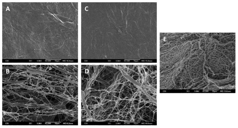
SEM images of the luminal surface of SIS (A), the abluminal surface of SIS (B), the luminal surface of UBM (C), the abluminal surface of UBM (D), and the surface of LECM (E). All images are 2500× magnification and scale bar = 10 μm.
The CDI-UBM demonstrated distinct structural differences in the arrangement of collagen fibers from those observed for GLUT-UBM and non-cross-linked UBM. Fibers on the abluminal side of the CDI-UBM appeared to coalesce to form a more dense, compact mesh of collagen with smaller pore sizes compared to non-cross-linked UBM and GLUT-UBM. The abluminal side of GLUT-UBM showed thicker bundles of collagen than were found in UBM; however, GLUT-UBM maintained a similar pore size to that observed on the abluminal side of non-cross-linked UBM. Fewer individual reticular and elastic fibers were observed in both CDI-UBM and GLUT-UBM than were observed in non-cross-linked UBM. The luminal sides of both CDI-UBM and GLUT-UBM exhibited a more fibrous surface topography as compared to non-cross-linked UBM. Representative SEM images of the surfaces of the cross-linked UBM scaffolds are shown in Figure 2.
Figure 2.
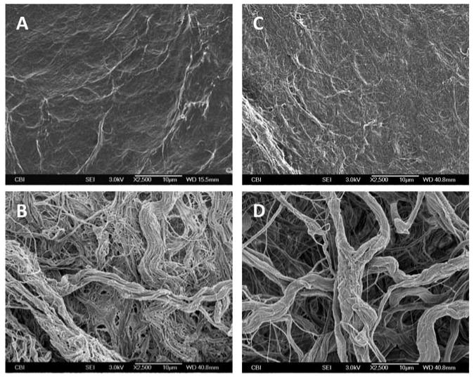
SEM images of the luminal surface of CDI-UBM (A), the abluminal surface of CDI-UBM (B), the luminal surface of GLUT-UBM (C), and the abluminal surface of GLUT-UBM. All images are 2500× magnification and scale bar = 10 μm.
3.2 Time of Flight Secondary Ion Mass Spectroscopy
In all of the samples investigated, the majority of the total ion yield was observed in the mass (m/z) 0-150 range with the exception of large peaks at m/z 166.06, 184.07, and 224.11, which were observed in the SIS and UBM as well as the cross-linked UBM samples but not the LECM samples. Representative positive ion spectra from the abluminal and luminal sides of the SIS and UBM samples along with spectra from the single sided LECM samples are shown in Figure 3. Figure 4 shows representative positive ion spectra for the luminal and abluminal sides of the CDI-UBM and GLUT-UBM samples.
Figure 3.

Representative positive ion spectra from the luminal surface of SIS (A), the abluminal surface of SIS (B), the luminal surface of UBM (C), the abluminal surface of UBM (D), and the surface of LECM (E).
Figure 4.

Representative positive ion spectra from the luminal surface of CDI-UBM (A), the abluminal surface of CDI-UBM (B), the luminal surface of GLUT-UBM (C), and the abluminal surface of GLUT-UBM.
The peak list used for PCA in the present study is a slightly abbreviated version of a previously published peak list [34, 35]. This list is comprised of peaks characteristic of unique amino acid mass fragmentation patterns created from model extracellular matrix protein surfaces analyzed with ToF-SIMS [34]. The peak set used for PCA in the present study is shown in Table 1. All PCA data is presented with 95% confidence intervals [35].
Table 1.
Positive Ion Fragment List for Multivariate Analysis with Amino Acids Adapted from Previous Worka
| Molecular Fragment | Mass | Prevalent Amino Acid | Extracellular Matrix Protein Association |
|---|---|---|---|
| CH4N | 30.036 | Gly | Collagen I |
| CH3N2 | 43.029 | Arg | Laminin |
| C2H6N | 44.052 | Ala/Cys | |
| C3H3O | 55.020 | Tyr | Fibronectin |
| C2H4NO | 58.029 | Gly | Collagen I |
| CH5N3 | 59.048 | Arg | Laminin |
| C2H6NO | 60.045 | Ser | Fibronectin |
| C2H5S | 61.011 | Met | Collagen I |
| C4H6N | 68.068 | Pro | Collagen I |
| C4H5O | 69.039 | Thr | Fibronectin |
| C3H4NO | 70.035 | Asn | Laminin |
| C3H3O2 | 71.013 | Ser | Fibronectin |
| C3H6NO | 72.047 | Gly | Collagen I |
| C4H10N | 72.088 | Val | Fibronectin |
| C2H7N3 | 73.070 | Arg | Laminin |
| C3H8NO | 74.065 | Thr | Fibronectin |
| C2H6NS | 76.028 | Cys | Laminin |
| C4H5N2 | 81.037 | His | |
| C5H7O | 83.053 | Val | Fibronectin |
| C4H6NO | 84.048 | Glu | Fibronectin |
| C5H10N | 84.086 | Lys | |
| C3H5N2O | 85.051 | Gly | Collagen I |
| C3H7N2O | 87.062 | Asn/Gly | |
| C3H6NO2 | 88.047 | Asn/Asp | |
| C5H7N2 | 95.060 | His | |
| C4H4NO2 | 98.024 | Asn | Laminin |
| C4H10N3 | 100.091 | Arg | Laminin |
| C4H11N3 | 101.038 | Arg | Laminin |
| C4H10NS | 104.070 | Met | Collagen I |
| C7H7O | 107.060 | Tyr | Fibronectin |
| C5H8N3 | 110.027 | Arg/His | |
| C4H5N2O2 | 113.052 | Gly | Collagen I |
| C4H7N2O2 | 115.059 | Gly | Collagen I |
| C5H9OS | 117.074 | Met | Collagen I |
| C8H10N | 120.099 | Phe | |
| C6H5N2O | 121.068 | His | |
| C5H11N4 | 127.096 | Arg | Laminin |
| C9H8O | 132.092 | Phe | |
| C8H10NO | 136.078 | Tyr | Fibronectin |
| C10H11N2 | 159.122 | Trp | Fibronectin |
| C11H8NO | 170.086 | Trp | Fibronectin |
Figure 5a shows principal component (PC) 1 vs. PC 2 for the non-cross-linked UBM, SIS, and LECM samples. Distinct differences were observed between the LECM samples and the luminal and abluminal surfaces of UBM and SIS. These differences were predominantly observed in PC 1, which accounted for 60% of the statistical separation of the total variance between all samples. It was observed that the peaks at m/z 30.036 (CH4N), 59.048 (CH5N3), and 68.068 (C4H6N) accounted for the majority of the loading on the LECM side of the PC 1 axis while peaks at m/z 72.088 (C4H10N), 115.059 (C4H7N2O2), and 117.074 (C5H9OS) accounted for the majority of the loading on the side of the PC 1 axis attributed to the UBM and SIS samples.
Figure 5.
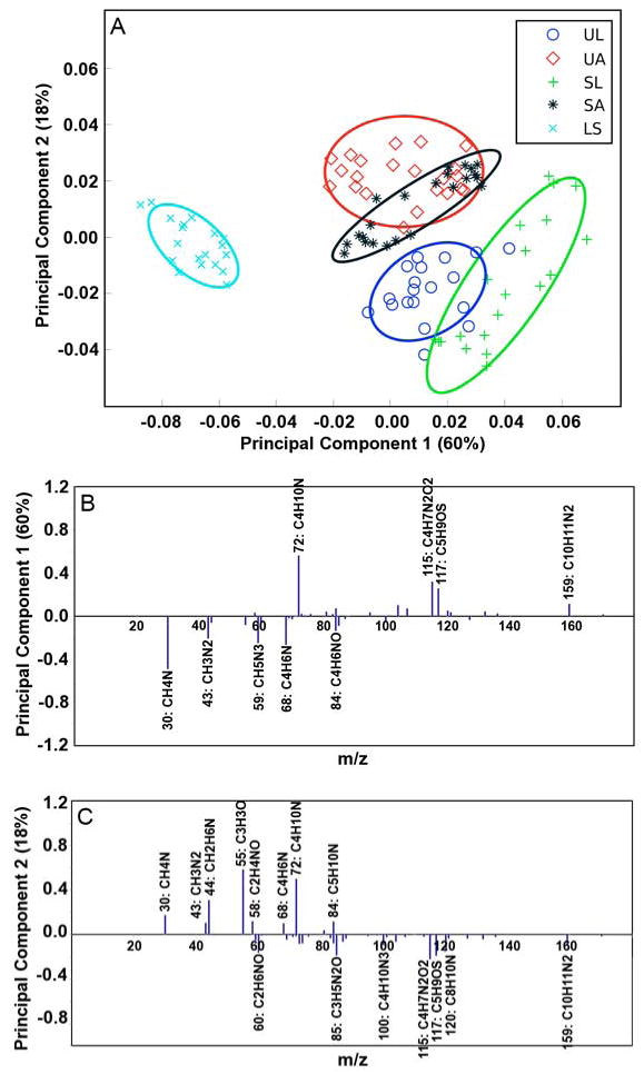
Principal component scores and loadings for UBM, SIS, and LECM samples. (A) PC1 vs. PC2 scores plot for the luminal surface of UBM (circle), the abluminal surface of UBM (diamond), the luminal surface of SIS (cross), the abluminal surface of SIS (asterisk), and the surface of LECM (x). All results are presented with 95% confidence interval (35). (B) Loadings for PC1. (C) Loadings for PC2. Peaks with loadings greater than 0.1 are labeled with their respective ion.
It was further observed that PC 2, which accounts for 18% of the total sample variance, was predominantly associated with differences between the luminal and abluminal surfaces of the UBM and SIS samples. More specifically, clear sample separation is seen in Figure 5a between the abluminal and the luminal surfaces of UBM. More overlap of the data in PC2 was observed in the luminal and abluminal surfaces of SIS than was observed for the UBM samples making clear differentiation of the peaks associated with each SIS surface difficult.
To better assess differences in the spectra taken from the luminal and abluminal sides of UBM, PCA was performed on ToF SIMS data taken from only the luminal and abluminal sides of UBM (i.e. data from SIS or LECM was not included). The scores and loadings for this comparison can be seen in Figure 6. Only PC 1 is shown as PC 2 for the abluminal and luminal sides of UBM did not capture discernable trends in the data. It was observed that PC 1, which accounted for 47% of the total sample variance, was associated with differences between the luminal and abluminal surfaces of UBM. Peaks at m/z 73.070 (C2H7N3), 115.059 (C4H7N2O2), and 117.074 (C5H9OS) were observed to account for the majority of the loading on the portion of the PC 1 axis associated with the luminal surface of UBM, while peaks at m/z 44.052 (C2H6N), 55.020 (C3H3O), and 72.088 (C4H10N) accounted for the majority of the loading associated with the abluminal surface of UBM. A similar analysis was performed for the abluminal and luminal surfaces of SIS; however, distinct peaks were not distinguishable due to overlap in the PCA data affiliated with the SIS surfaces (data not shown).
Figure 6.

Principal component 1 scores and loadings for the luminal surface of UBM (circle) and the abluminal surface of UBM (x). Only PC1 is presented. All results are presented with 95% confidence interval (35). (B) Loadings for PC1. Peaks with loadings greater than 0.1 are labeled with their respective ion.
For the analysis of the differences between the surfaces of cross-linked and non-cross-linked UBM samples, spectra obtained from the CDI and GLUT treated UBM samples were compared to those obtained from the non-cross-linked samples used above. Overlapping of the data was observed in the PCA analysis when performed on the luminal and abluminal surfaces of UBM, CDI-UBM, and GLUT-UBM together. However, more distinct trends were observed when the luminal sides of UBM, CDI-UBM, and GLUT-UBM were examined separately. The scores and loadings for this analysis are shown in Figure 7.
Figure 7.
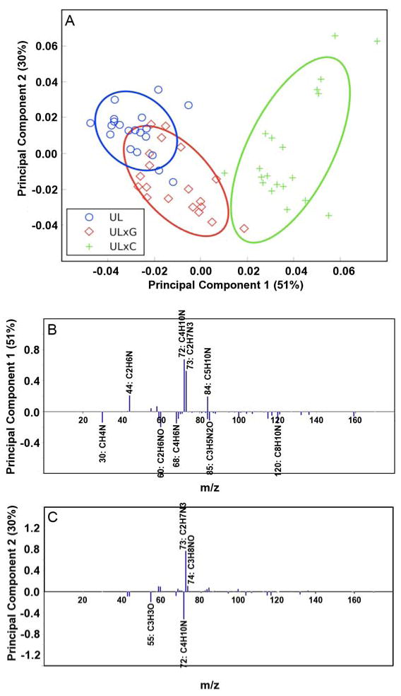
Principal component scores and loadings for the luminal sides of UBM, UBM-CDI (ULxC) and UBM-GLUT (ULxG) samples. (A) PC1 vs. PC2 scores plot for the luminal surface of UBM (circle), the luminal surface of UBM-GLUT (diamond), and the luminal surface of UBM-CDI (cross). All results are presented with 95% confidence interval (35). (B) Loadings for PC1. (C) Loadings for PC2. Peaks with loadings greater than 0.1 are labeled with their respective ion.
In Figure 7a, separation associated with the non-cross-linked samples as compared to the two cross-linked samples can be observed. PC 1, which captures 51% of the total variance, can be used to clearly differentiate the CDI cross-linked sample from the non-cross-linked sample while there is some overlap of the glutaraldehyde cross-linked sample with non-cross-linked UBM surface. In PC 2, which captures 30% of the variance, the samples are not statistically distinct, but the graphical locations of the 95% confidence intervals suggest that differences may exist and further characterization of these distinctions could be done in future work. A similar analysis was performed on the abluminal sides of UBM, CDI-UBM, and GLUT-UBM, but the comparisons are not included as trends were difficult to extract due to overlapping loadings.
4. Discussion
In tissue engineering and regenerative medicine applications, the cells that participate in the processes of tissue reconstruction require “instruction” for proliferation, morphogenesis, and differentiation. The sources of this “instruction” are the cellular microenvironment and the scaffold or matrix surfaces with which these cells interact. Factors known to influence the outcome of cell-scaffold interactions include surface topography [36-40], hydrophilicity/hydrophobicity [41-44], ligand presence and presentation [45-50], and mechanical properties [51-55], among numerous others. Further, the success of a given cell-scaffold combination may be highly dependant on the type of cell being examined. Therefore, it is essential to characterize and consider the surface of a scaffold as well as its effects upon cell phenotype when designing a strategy to facilitate the reconstruction of complex three-dimensional tissues and organs.
Scaffolds composed of single purified ECM components as well as scaffolds composed of intact ECM have been investigated in a large number of in vitro and in vivo tissue engineering and regenerative medicine applications with varying degrees of success. The advantage of using intact acellular ECM as a scaffold for cell growth or reconstructive remodeling as opposed to the individual components of the ECM includes the presence of all the ECM constituents in the same relative amounts as exist in nature and in an ultrastructure similar to that of native ECM. It remains unclear, however, whether the molecular composition or the ultrastructure of these scaffolds plays a greater role in determining the outcome of the interaction of cells with the scaffold material. Likely, it is the diverse combination of both the structural and the functional components present within ECM scaffolds that accounts for the success of ECM based materials in multiple organ systems.
The present study examined the ultrastructural and compositional characteristics of the surfaces of porcine ECM scaffolds harvested from three different anatomical locations: (1) urinary bladder, (2) small intestine, and (3) liver. SEM showed that the ECM derived from each of the three anatomical locations possessed a distinct ultrastructure. Further evaluation of these same scaffolds using ToF-SIMS showed that that UBM and SIS had more similar surface compositions when compared to each other than when compared to LECM. There is evidence that these differences, which appear to be related to the tissue source from which an ECM scaffold is derived, may play a role in modulating or maintaining the phenotype of cells that have been seeded into the matrix [17, 21, 31, 56]. A recent study investigated the ability of the same three porcine derived ECM scaffolds that were used in the present study to maintain the phenotype of a hepatic sinusoidal endothelial cell population during in vitro cell culture [21]. The results showed that the LECM scaffolds were capable of maintaining the specialized endothelial cell phenotype in culture both to a greater degree and for a longer duration than were the UBM or SIS scaffolds.
In the present study, it was also observed that certain ECM scaffolds (UBM and SIS) exhibited distinct ultrastructural differences depending on the sidedness (i.e. luminal versus abluminal) of the scaffold while others exhibited an ultrastructure that was more homogeneous throughout (LECM). Evaluation of the scaffolds by ToF-SIMS showed that UBM exhibited significant differences in the composition of the luminal and abluminal surfaces, while SIS exhibited overlapping composition of the luminal and abluminal surfaces. These results parallel previous in vitro immunohistochemical studies which showed that UBM, but not SIS or LECM, scaffolds possessed an intact basement membrane on their luminal surface [17]. The presence of a basement membrane was further shown to play a role in modulating cell growth patterns. Specifically, it was shown that the presence of a basement membrane surface promoted the growth of confluent monolayers of NIH 3T3 fibroblasts as well as human microvascular endothelial cells on the luminal surface of UBM scaffolds, while more invasive ingrowth of the cells was observed through the abluminal surface of the UBM scaffold or either surface of the SIS and LECM scaffolds.
Chemical cross-linking is a process commonly used in the production of ECM scaffolds to slow or prevent degradation of the resultant scaffold, to inhibit the recognition of surface epitopes by the host, and to provide improved mechanical properties for load bearing applications. The present study examined the effects of chemical cross-linking upon the surface characteristics of the urinary bladder derived extracellular matrix scaffold. It was observed that chemical cross-linking caused changes in the ultrastructure of both the luminal and abluminal sides of UBM. However, chemical cross-linking appeared to cause only minimal changes in the molecular composition of the scaffold surface as observed by ToF-SIMS. It is logical to assume that cross-linking may also be responsible for altering the presentation and conformation of ligands on the surface of an ECM scaffold, thus altering the ligand-receptor interactions which may be important in determining the outcome of cell-scaffold interactions; however, it was not possible to fully assess these changes in the present study. Further characterization of the surface of cross-linked ECM scaffolds by ToF-SIMS and other methods may provide insights into the effects of cross-linking upon the cellular response.
Studies have shown significant differences in the host response to chemically cross-linked ECM scaffolds [26, 27, 57]. Inhibiting ECM scaffold degradation via chemical cross-linking has been shown to lead to a less constructive remodeling response, which includes chronic inflammation and the deposition of fibrous connective tissue at the surface of the implanted material [26]. Further investigation of the host response to cross-linked and non-cross-linked ECM scaffolds has shown that there are differences in the phenotype of the macrophages that participate in the remodeling of the scaffold following implantation [27]. That is, it has been shown that the implantation of a chemically cross-linked ECM scaffold is associated with the formation of a predominantly M1 type macrophage response while implantation of a non-cross-linked ECM scaffold is associated with a predominantly M2 type macrophage response [27]. The M1 response leads to fibrous tissue encapsulation while the M2 response is characterized by a constructive tissue remodeling outcome [27, 58]. The exact mechanisms which underlie the observed differences remain unknown; however, it is clear that each ECM scaffold and its respective surface characteristics are associated with differences in both in vitro and in vivo cellular responses.
ToF-SIMS as a tool for studying the surface of protein based materials is novella recent concept, and the present study represents the first attempt to use ToF-SIMS as a tool for compositional analysis and differentiation of the surfaces of highly complex ECM based scaffolds. In the present study, ToF-SIMS was capable of identifying differences in the compositions of the various surfaces investigated and the results obtained parallel those of previous studies investigating the surfaces of ECM scaffolds using other techniques [17]. There are, however, a number of limitations in the application of ToF-SIMS to the analysis of the surface of a biologically derived material.
Due to the inherent mass range limitation of ToF-SIMS, it is not possible to assess whole proteins or peptide sequences. Rather, the method relies on analysis of mass fragmentation patterns. Previous studies have shown successful correlations between such fragmentation patterns and protein surfaces [34, 35]. In one such study, known amino acid mass fragmentation patterns generated from ToF-SIMS were compared to the mass spectra obtained for extracellular matrix proteins remaining on a polyNIPAM surface following the removal of cultured bovine aortic endothelial cells. The mass spectra obtained for single purified ECM components adsorbed onto the polyNIPAM surface were the reference spectra for the present study [34]. The results showed that ToF-SIMS was capable of detecting protein fragment fingerprints for laminin, fibronectin, and collagen within the film remaining on the culture surface by comparing the protein remnants to single protein film controls. A slightly variant version of this peak list was utilized for this study (Table 1).
In the present study, the complexity of the surfaces makes it difficult to report a one-to-one correlation between fragment and implied protein association. Therefore, it is likely more useful to report the data obtained as a list of prominent fragments as opposed to suggesting that the fragments indicate specific proteins. The complicated surface milieu of these materials and the relative lack of data on specific fragmentation patterns of many purified ECM components justify this approach. On the other hand, this approach suggests that identification of unknown molecules may be achievable. This possibility for the unique identification of surface structures and features was part of the original hypothesis that was the impetus for this study. Traditional antibody-based immunohistochemsitry requires prior knowledge of the surface proteins as a prerequisite for their identification. In the present approach, the potential to identify molecules both expected and unexpected exists, aiding in the creation of a unique picture of the material surface chemistry and functionality on a molecular level.
In addition to using amino acid mass fragmentation peaks identified in the studies relating ToF-SIMS spectra to protein films, spectra taken from the surfaces in this study were cross-examined with previously published lipid peak lists [59]. The identification of large peaks at m/z 166.06, 184.07, and 224.11 in the spectra for SIS and UBM as well as cross-linked UBM indicates lipid structures and likely cell membrane components. Interestingly, these peaks were not observed to the same extent in the LECM scaffolds. This may be due to the different methods used for the decellularization of the SIS/UBM and LECM in this study. The existence of peaks found in the high mass region was not limited to the large peaks mentioned above. Low intensity lipid peaks were identified throughout the high mass region that matched previously published lipid work (data not shown). However, the focus of this work was to create a fingerprint of the protein remnants and future work more completely characterize the lipid fragments.
Finally, it should be noted that the present study is a continuation of several studies intended to characterize the surfaces of ECM scaffolds and their effects upon cell phenotype [17, 21, 22, 56]. The present study sought only to characterize the ultrastructure and molecular composition of the surfaces of ECM scaffolds. Further work will relate this data to cell behavior both in vitro and in vivo. Previous studies have used methods such as partial least squares regression to relate ToF-SIMS data to subsequent in vitro cell culture observations [60]. Similar studies could be performed to compare the present ToF-SIMS data to the morphologic or phenotypic profiles of cells cultured on ECM scaffolds or following in vivo implantation.
5. Conclusion
The results of the present study demonstrated that each surface of an ECM scaffold is associated with distinct ultrastructural and compositional characteristics and that these surface characteristics are dependant on both the anatomic location from which the material is derived as well as the methods used in its production (i.e. decellularization and chemical cross-linking). It was also demonstrated that ToF-SIMS is a highly sensitive method for the detection and differentiation of the molecular composition of the outermost surface of an ECM scaffold. Further, ToF-SIMS may represent a method for future identification of previously unknown surface species as well as for the prediction of cell-scaffold interactions and subsequent remodeling events. Finally, the richness of molecular detail in the ToF-SIMS spectra suggests that ToF-SIMS may be useful for quality control of commercialized ECM-based regenerative scaffold products and for standardization of these scaffolds.
Acknowledgments
Bryan Brown and Chris Barnes contributed equally to the preparation of this manuscript and to the work described herein. The ToF-SIMS/PCA experiments were done at the National ESCA and Surface Analysis Center for Biomedical Problems, which is supported by NIH grant EB-002027. Jeremy Brison is thanked for technical discussions.
Footnotes
Publisher's Disclaimer: This is a PDF file of an unedited manuscript that has been accepted for publication. As a service to our customers we are providing this early version of the manuscript. The manuscript will undergo copyediting, typesetting, and review of the resulting proof before it is published in its final citable form. Please note that during the production process errors may be discovered which could affect the content, and all legal disclaimers that apply to the journal pertain.
References
- 1.Baker SC, Southgate J. Towards control of smooth muscle cell differentiation in synthetic 3D scaffolds. Biomaterials. 2008;29(23):3357–66. doi: 10.1016/j.biomaterials.2008.04.033. [DOI] [PubMed] [Google Scholar]
- 2.Bissell MJ, Hall HG, Parry G. How does the extracellular matrix direct gene expression? J Theor Biol. 1982;99(1):31–68. doi: 10.1016/0022-5193(82)90388-5. [DOI] [PubMed] [Google Scholar]
- 3.Boudreau N, Myers C, Bissell MJ. From laminin to lamin: regulation of tissue-specific gene expression by the ECM. Trends Cell Biol. 1995;5(1):1–4. doi: 10.1016/s0962-8924(00)88924-2. [DOI] [PubMed] [Google Scholar]
- 4.Ingber D. Extracellular matrix and cell shape: potential control points for inhibition of angiogenesis. J Cell Biochem. 1991;47(3):236–41. doi: 10.1002/jcb.240470309. [DOI] [PubMed] [Google Scholar]
- 5.Davis GE, Senger DR. Endothelial extracellular matrix: biosynthesis, remodeling, and functions during vascular morphogenesis and neovessel stabilization. Circ Res. 2005;97(11):1093–107. doi: 10.1161/01.RES.0000191547.64391.e3. [DOI] [PubMed] [Google Scholar]
- 6.Atala A, Bauer SB, Soker S, Yoo JJ, Retik AB. Tissue-engineered autologous bladders for patients needing cystoplasty. Lancet. 2006;367(9518):1241–6. doi: 10.1016/S0140-6736(06)68438-9. [DOI] [PubMed] [Google Scholar]
- 7.Atala A, Freeman MR, Vacanti JP, Shepard J, Retik AB. Implantation in vivo and retrieval of artificial structures consisting of rabbit and human urothelium and human bladder muscle. J Urol. 1993;150(2 Pt 2):608–12. doi: 10.1016/s0022-5347(17)35561-1. [DOI] [PubMed] [Google Scholar]
- 8.Demirbilek S, Kanmaz T, Ozardali I, Edali MN, Yucesan S. Using porcine small intestinal submucosa in intestinal regeneration. Pediatr Surg Int. 2003;19(8):588–92. doi: 10.1007/s00383-003-1025-2. [DOI] [PubMed] [Google Scholar]
- 9.Kropp BP, Cheng EY, Lin HK, Zhang Y. Reliable and reproducible bladder regeneration using unseeded distal small intestinal submucosa. J Urol. 2004;172(4 Pt 2):1710–3. doi: 10.1097/01.ju.0000139952.64753.27. [DOI] [PubMed] [Google Scholar]
- 10.Mantovani F, Trinchieri A, Castelnuovo C, Romano AL, Pisani E. Reconstructive urethroplasty using porcine acellular matrix. Eur Urol. 2003;44(5):600–2. doi: 10.1016/s0302-2838(03)00212-4. [DOI] [PubMed] [Google Scholar]
- 11.McCready RA, Hodde J, Irwin RJ, Coffey AC, Divelbiss JL, Bryant MA, et al. Pseudoaneurysm formation in a subset of patients with small intestinal submucosa biologic patches after carotid endarterectomy. J Vasc Surg. 2005;41(5):782–8. doi: 10.1016/j.jvs.2005.02.035. [DOI] [PubMed] [Google Scholar]
- 12.Musahl V, Abramowitch SD, Gilbert TW, Tsuda E, Wang JH, Badylak SF, et al. The use of porcine small intestinal submucosa to enhance the healing of the medial collateral ligament--a functional tissue engineering study in rabbits. J Orthop Res. 2004;22(1):214–20. doi: 10.1016/S0736-0266(03)00163-3. [DOI] [PubMed] [Google Scholar]
- 13.Pu LL. Small intestinal submucosa (Surgisis) as a bioactive prosthetic material for repair of abdominal wall fascial defect. Plast Reconstr Surg. 2005;115(7):2127–31. doi: 10.1097/01.prs.0000168883.65715.2f. [DOI] [PubMed] [Google Scholar]
- 14.Sardeli C, Axelsen SM, Bek KM. Use of porcine small intestinal submucosa in the surgical treatment of recurrent rectocele in a patient with Ehlers-Danlos syndrome type III. Int Urogynecol J Pelvic Floor Dysfunct. 2005;16(6):504–5. doi: 10.1007/s00192-004-1265-2. [DOI] [PubMed] [Google Scholar]
- 15.Schultheiss D, Gabouev AI, Cebotari S, Tudorache I, Walles T, Schlote N, et al. Biological vascularized matrix for bladder tissue engineering: matrix preparation, reseeding technique and short-term implantation in a porcine model. J Urol. 2005;173(1):276–80. doi: 10.1097/01.ju.0000145882.80339.18. [DOI] [PubMed] [Google Scholar]
- 16.Ueno T, Pickett LC, de la Fuente SG, Lawson DC, Pappas TN. Clinical application of porcine small intestinal submucosa in the management of infected or potentially contaminated abdominal defects. J Gastrointest Surg. 2004;8(1):109–12. doi: 10.1016/j.gassur.2003.09.025. [DOI] [PubMed] [Google Scholar]
- 17.Brown B, Lindberg K, Reing J, Stolz DB, Badylak SF. The basement membrane component of biologic scaffolds derived from extracellular matrix. Tissue Eng. 2006;12(3):519–26. doi: 10.1089/ten.2006.12.519. [DOI] [PubMed] [Google Scholar]
- 18.Hodde J, Janis A, Hiles M. Effects of sterilization on an extracellular matrix scaffold: part II. Bioactivity and matrix interaction. Journal of materials science. 2007;18(4):545–50. doi: 10.1007/s10856-007-2301-9. [DOI] [PubMed] [Google Scholar]
- 19.Hodde JP, Record RD, Tullius RS, Badylak SF. Retention of endothelial cell adherence to porcine-derived extracellular matrix after disinfection and sterilization. Tissue engineering. 2002;8(2):225–34. doi: 10.1089/107632702753724996. [DOI] [PubMed] [Google Scholar]
- 20.Gilbert TW, Stewart-Akers AM, Sydeski J, Nguyen TD, Badylak SF, Woo SL. Gene expression by fibroblasts seeded on small intestinal submucosa and subjected to cyclic stretching. Tissue engineering. 2007;13(6):1313–23. doi: 10.1089/ten.2006.0318. [DOI] [PubMed] [Google Scholar]
- 21.Sellaro TL, Ravindra AK, Stolz DB, Badylak SF. Maintenance of Hepatic Sinusoidal Endothelial Cell Phenotype In Vitro Using Organ-Specific Extracellular Matrix Scaffolds. Tissue Eng. 2007;13(9):2301–10. doi: 10.1089/ten.2006.0437. [DOI] [PubMed] [Google Scholar]
- 22.Valentin JE, Freytes DO, Grasman JM, Pesyna C, Freund J, Gilbert TW, et al. Oxygen diffusivity of biologic and synthetic scaffold materials for tissue engineering. J Biomed Mater Res A. 2008 doi: 10.1002/jbm.a.32328. Epub ahead of print. [DOI] [PubMed] [Google Scholar]
- 23.Freytes DO, Tullius RS, Badylak SF. Effect of storage upon material properties of lyophilized porcine extracellular matrix derived from the urinary bladder. J Biomed Mater Res B. 2006;78(2):327–33. doi: 10.1002/jbm.b.30491. [DOI] [PubMed] [Google Scholar]
- 24.Freytes DO, Tullius RS, Valentin JE, Stewart-Akers AM, Badylak SF. Hydrated versus lyophilized forms of porcine extracellular matrix derived from the urinary bladder. J Biomed Mater Res A. 2008;87(4):862–72. doi: 10.1002/jbm.a.31821. [DOI] [PubMed] [Google Scholar]
- 25.Gilbert TW, Sellaro TL, Badylak SF. Decellularization of tissues and organs. Biomaterials. 2006;27(19):3675–83. doi: 10.1016/j.biomaterials.2006.02.014. [DOI] [PubMed] [Google Scholar]
- 26.Valentin JE, Badylak JS, McCabe GP, Badylak SF. Extracellular matrix bioscaffolds for orthopaedic applications. A comparative histologic study. J Bone Joint Surg Am. 2006;88(12):2673–86. doi: 10.2106/JBJS.E.01008. [DOI] [PubMed] [Google Scholar]
- 27.Badylak SF, Valentin JE, Ravindra AK, McCabe GP, Stewart-Akers AM. Macrophage phenotype as a determinant of biologic scaffold remodeling. Tissue Eng Part A. 2008;14(11):1835–42. doi: 10.1089/ten.tea.2007.0264. [DOI] [PubMed] [Google Scholar]
- 28.Belu AM, Graham DJ, Castner DG. Time-of-flight secondary ion mass spectrometry: techniques and applications for the characterization of biomaterial surfaces. Biomaterials. 2003;24(21):3635–53. doi: 10.1016/s0142-9612(03)00159-5. [DOI] [PubMed] [Google Scholar]
- 29.Freytes DO, Badylak SF, Webster TJ, Geddes LA, Rundell AE. Biaxial strength of multilaminated extracellular matrix scaffolds. Biomaterials. 2004;25(12):2353–61. doi: 10.1016/j.biomaterials.2003.09.015. [DOI] [PubMed] [Google Scholar]
- 30.Badylak SF, Lantz GC, Coffey A, Geddes LA. Small intestinal submucosa as a large diameter vascular graft in the dog. J Surg Res. 1989;47(1):74–80. doi: 10.1016/0022-4804(89)90050-4. [DOI] [PubMed] [Google Scholar]
- 31.Lin P, Chan WC, Badylak SF, Bhatia SN. Assessing porcine liver-derived biomatrix for hepatic tissue engineering. Tissue Eng. 2004;10(78):1046–53. doi: 10.1089/ten.2004.10.1046. [DOI] [PubMed] [Google Scholar]
- 32.Jackson JE. A user's guide to principal components. New York: Wiley; 1991. [Google Scholar]
- 33.Ushiki T. Collagen fibers, reticular fibers and elastic fibers. A comprehensive understanding from a morphological viewpoint. Arch Histol Cytol. 2002;65(2):109–26. doi: 10.1679/aohc.65.109. [DOI] [PubMed] [Google Scholar]
- 34.Canavan HE, Graham DJ, Cheng X, Ratner BD, Castner DG. Comparison of native extracellular matrix with adsorbed protein films using secondary ion mass spectrometry. Langmuir. 2007;23(1):50–6. doi: 10.1021/la062330o. [DOI] [PubMed] [Google Scholar]
- 35.Wagner MS, Castner DG. Characterization of Adsorbed Protein Films by Time-of-Flight Secondary Ion Mass Spectroscopy with Principal Component Analysis. Langmuir. 2001;17(15):4649–60. [Google Scholar]
- 36.Bettinger CJ, Langer R, Borenstein JT. Engineering Substrate Topography at the Micro- and Nanoscale to Control Cell Function. Angew Chem Int Ed Engl. 2009;48(30):5406–15. doi: 10.1002/anie.200805179. [DOI] [PMC free article] [PubMed] [Google Scholar]
- 37.Flemming RG, Murphy CJ, Abrams GA, Goodman SL, Nealey PF. Effects of synthetic micro- and nano-structured surfaces on cell behavior. Biomaterials. 1999;20(6):573–88. doi: 10.1016/s0142-9612(98)00209-9. [DOI] [PubMed] [Google Scholar]
- 38.Loesberg WA, te Riet J, van Delft FC, Schon P, Figdor CG, Speller S, et al. The threshold at which substrate nanogroove dimensions may influence fibroblast alignment and adhesion. Biomaterials. 2007;28(27):3944–51. doi: 10.1016/j.biomaterials.2007.05.030. [DOI] [PubMed] [Google Scholar]
- 39.Henry JA, Burugapalli K, Neuenschwander P, Pandit A. Structural variants of biodegradable polyesterurethane in vivo evoke a cellular and angiogenic response that is dictated by architecture. Acta Biomater. 2009;5(1):29–42. doi: 10.1016/j.actbio.2008.08.020. [DOI] [PubMed] [Google Scholar]
- 40.Koh HS, Yong T, Chan CK, Ramakrishna S. Enhancement of neurite outgrowth using nano-structured scaffolds coupled with laminin. Biomaterials. 2008;29(26):3574–82. doi: 10.1016/j.biomaterials.2008.05.014. [DOI] [PubMed] [Google Scholar]
- 41.Chang DT, Jones JA, Meyerson H, Colton E, Kwon IK, Matsuda T, et al. Lymphocyte/macrophage interactions: biomaterial surface-dependent cytokine, chemokine, and matrix protein production. J Biomed Mater Res A. 2008;87(3):676–87. doi: 10.1002/jbm.a.31630. [DOI] [PMC free article] [PubMed] [Google Scholar]
- 42.Ivirico JL, Salmeron-Sanchez M, Ribelles JL, Pradas MM, Soria JM, Gomes ME, et al. Proliferation and differentiation of goat bone marrow stromal cells in 3D scaffolds with tunable hydrophilicity. J Biomed Mater Res B Appl Biomater. 2009 doi: 10.1002/jbm.b.31400. Epub ahead of print. [DOI] [PubMed] [Google Scholar]
- 43.Hezi-Yamit A, Sullivan C, Wong J, David L, Chen M, Cheng P, et al. Impact of polymer hydrophilicity on biocompatibility: implication for DES polymer design. J Biomed Mater Res A. 2009;90(1):133–41. doi: 10.1002/jbm.a.32057. [DOI] [PubMed] [Google Scholar]
- 44.Jansen EJ, Sladek RE, Bahar H, Yaffe A, Gijbels MJ, Kuijer R, et al. Hydrophobicity as a design criterion for polymer scaffolds in bone tissue engineering. Biomaterials. 2005;26(21):4423–31. doi: 10.1016/j.biomaterials.2004.11.011. [DOI] [PubMed] [Google Scholar]
- 45.Bernards MT, Qin C, Ratner BD, Jiang S. Adhesion of MC3T3-E1 cells to bone sialoprotein and bone osteopontin specifically bound to collagen I. J Biomed Mater Res A. 2008;86(3):779–87. doi: 10.1002/jbm.a.31650. [DOI] [PMC free article] [PubMed] [Google Scholar]
- 46.Hubbell JA, Massia SP, Desai NP, Drumheller PD. Endothelial cell-selective materials for tissue engineering in the vascular graft via a new receptor. Biotechnology (N Y) 1991;9(6):568–72. doi: 10.1038/nbt0691-568. [DOI] [PubMed] [Google Scholar]
- 47.Quirk RA, Kellam B, Bhandari RN, Davies MC, Tendler SJ, Shakesheff KM. Cell-type-specific adhesion onto polymer surfaces from mixed cell populations. Biotechnol Bioeng. 2003;81(5):625–8. doi: 10.1002/bit.10502. [DOI] [PubMed] [Google Scholar]
- 48.Beckstead BL, Santosa DM, Giachelli CM. Mimicking cell-cell interactions at the biomaterial-cell interface for control of stem cell differentiation. J Biomed Mater Res A. 2006;79(1):94–103. doi: 10.1002/jbm.a.30760. [DOI] [PubMed] [Google Scholar]
- 49.Hodde J, Record R, Tullius R, Badylak S. Fibronectin peptides mediate HMEC adhesion to porcine-derived extracellular matrix. Biomaterials. 2002;23(8):1841–8. doi: 10.1016/s0142-9612(01)00310-6. [DOI] [PubMed] [Google Scholar]
- 50.Liu L, Chen S, Giachelli CM, Ratner BD, Jiang S. Controlling osteopontin orientation on surfaces to modulate endothelial cell adhesion. J Biomed Mater Res A. 2005;74(1):23–31. doi: 10.1002/jbm.a.30221. [DOI] [PubMed] [Google Scholar]
- 51.Mitragotri S, Lahann J. Physical approaches to biomaterial design. Nat Mater. 2009;8(1):15–23. doi: 10.1038/nmat2344. [DOI] [PMC free article] [PubMed] [Google Scholar]
- 52.Rehfeldt F, Engler AJ, Eckhardt A, Ahmed F, Discher DE. Cell responses to the mechanochemical microenvironment--implications for regenerative medicine and drug delivery. Adv Drug Deliv Rev. 2007;59(13):1329–39. doi: 10.1016/j.addr.2007.08.007. [DOI] [PMC free article] [PubMed] [Google Scholar]
- 53.Engler AJ, Carag-Krieger C, Johnson CP, Raab M, Tang HY, Speicher DW, et al. Embryonic cardiomyocytes beat best on a matrix with heart-like elasticity: scar-like rigidity inhibits beating. J Cell Sci. 2008;121(Pt 22):3794–802. doi: 10.1242/jcs.029678. [DOI] [PMC free article] [PubMed] [Google Scholar]
- 54.Engler AJ, Sen S, Sweeney HL, Discher DE. Matrix elasticity directs stem cell lineage specification. Cell. 2006;126(4):677–89. doi: 10.1016/j.cell.2006.06.044. [DOI] [PubMed] [Google Scholar]
- 55.Ghosh K, Ingber DE. Micromechanical control of cell and tissue development: implications for tissue engineering. Adv Drug Deliv Rev. 2007;59(13):1306–18. doi: 10.1016/j.addr.2007.08.014. [DOI] [PubMed] [Google Scholar]
- 56.Bhrany AD, Beckstead BL, Lang TC, Farwell DG, Giachelli CM, Ratner BD. Development of an esophagus acellular matrix tissue scaffold. Tissue Eng. 2006;12(2):319–30. doi: 10.1089/ten.2006.12.319. [DOI] [PubMed] [Google Scholar]
- 57.Liang HC, Chang Y, Hsu CK, Lee MH, Sung HW. Effects of cross-linking degree of an acellular biological tissue on its tissue regeneration pattern. Biomaterials. 2004;25(17):3541–52. doi: 10.1016/j.biomaterials.2003.09.109. [DOI] [PubMed] [Google Scholar]
- 58.Brown BN, Valentin JE, Stewart-Akers AM, McCabe GP, Badylak SF. Macrophage phenotype and remodeling outcomes in response to biologic scaffolds with and without a cellular component. Biomaterials. 2009;30(8):1482–91. doi: 10.1016/j.biomaterials.2008.11.040. [DOI] [PMC free article] [PubMed] [Google Scholar]
- 59.Baker MJ, Zheng L, Winograd N, Lockyer NP, Vickerman JC. Mass spectral imaging of glycophospholipids, cholesterol, and glycophorin a in model cell membranes. Langmuir. 2008;24(20):11803–10. doi: 10.1021/la802582f. [DOI] [PMC free article] [PubMed] [Google Scholar]
- 60.Chilkoti A, Schmierer AE, Perez-Luna VH, Ratner BD. Investigating the relationship between surface chemistry and endothelial cell growth: partial least-squares regression of the static secondary ion mass spectra of oxygen-containing plasma-deposited films. Anal Chem. 1995;67(17):2883–91. doi: 10.1021/ac00113a024. [DOI] [PubMed] [Google Scholar]