Abstract
We previously used a combination of CW and pulsed-ENDOR protocols to identify the types of protonated oxygen (OHx) species and their disposition within the FeIII/FeIV cluster of Intermediate X, the direct precursor of the essential diferric-tyrosyl radical cofactor of the β2 subunit of Escherichia coli ribonucleotide reductase (RNR). We concluded that X contains the [(HxO)FeIIIOFeIV] fragment (T model), and does not contain a μ–hydroxo bridge. When combined with a subsequent 17O ENDOR study of X prepared with H217O and with 17O2, the results led us to suggest that this fragment is the entire inorganic core of X. This has been questioned by recent reports, but these reports do not themselves agree on the core of X. An experimental/computational study that included rapid freeze quench magnetic circular dichroism measurements and TD-DFT calculations [Mitic, N.; Clay, M. D.; Saleh, L.; Bollinger, J. M.; Solomon, E. I. J. Am. Chem. Soc. 2007, 129, 9049–9065] proposed that X has a μ-oxo/μ-hydroxo FeIII/FeIV core, without addressing the existence of terminal (HxO). In a series of computational studies, Noodleman and coworkers instead concluded that X possesses a di-μ–oxo FeIII/FeIV core plus a terminal (H2O) bound to FeIII [eg., Han, W.-G.; Liu, T.; Lovell, T.; Noodleman, L. J. Am. Chem. Soc. 2005, 127, 15778–15790]. In this report we take advantage of improvements in 35 GHz pulsed-ENDOR performance to reexamine the protonation state of the oxygenic ligands of the inorganic core of X by directly probing the exchangeable proton(s) with 2H pulsed-ENDOR spectroscopy. These 2H ENDOR measurements confirm that X contains an FeIII-bound terminal aqua ligand (HxO), but the spectra contain none of the features that would be required for the proton of a bridging hydroxyl. Thus, we confirm that X contains a terminal aqua (plausibly hydroxo) ligand to FeIII in addition to one or two μ–oxo bridges, but does not contain a μ–hydroxo bridge. The 2H ENDOR measurements further demonstrate that this conclusion is applicable to both the WT and Y122F-β2, and in fact detect no difference between the properties of protons on the terminal oxygens in the two variants; likewise, 14N ENDOR measurements of histidyl ligands bound to Fe show no difference between the two variants.
Introduction
Diferrous non-heme iron proteins carry out a broad range of reactions, ranging from reversible O2 binding to fatty acid desaturation and methane oxidation, and the factors that govern O2 activation in such diverse reactions are of intense interest.1–4 The β2 (R2) subunit of class 1a and 1b Escherichia coli ribonucleotide reductases (RNR) are such proteins. These RNRs catalyze the conversion of nucleoside diphosphates to deoxynucleoside diphosphates in reactions involving complex free radical chemistry.5–7 The β2 subunits in their oxidized forms/states contain a non-heme diferric center adjacent to a tyrosyl radical (Y•)8,9 that initiates the reduction process. The active diferric-Y• cofactor is generated from the diferrous-Y center in a reaction with O2 and an external reductant. This process has been studied by a number of time-resolved biophysical methods, including stopped flow spectroscopy and rapid freeze-quench (RFQ) EPR, ENDOR, Mössbauer, MCD and EXAFS spectroscopies.10–16 A paramagnetic diiron intermediate designated X has been observed by all of these methods. X is one-electron oxidized relative to the resting diferric state of β2 and is catalytically competent to oxidize tyrosine 122 to Y122•.17,18 RFQ Q-band 57Fe ENDOR spectroscopy19 established that the diiron center of X has an antiferromagnetically spin coupled FeIII(S = 5/2)/FeIV(S = 2) core with an S = ½ ground state.
Efforts to assign the structure(s) of X have been influenced by crystallographically determined structures of β2 in the diferrous state, of the tyrosyl radical reduced diferric state, and of several β2 mutants. In the diferrous state the two irons are separated by 3.9 Å with Fe1, adjacent to the tyrosine 122 that is oxidized, being 4 coordinate and Fe2 being 5 coordinate.20,21 In this state there are no ligands from the solvent; there are two glutamates, E115 and E238, that bridge the two iron centers in a μ-1,3 fashion. In addition, Fe1 is coordinated to H118 and D84, which also is H bonded to Y122. During the conversion to the diferric cluster,22,23 the iron centers move closer together (3.3 Å), E115 forms a single carboxylate bridge in a μ-1,3 fashion, and a single μ-oxo bridge is formed from O2. Both iron ions become 6 coordinate. Fe1 also is coordinated to H118, bidentate to D84, and to a water or hydroxide, whereas Fe2 is coordinated to H241, monodentate to E238 and E204 and a terminal solvent molecule. Thus during the formation of active cofactor from the diferrous state, two terminal (HxO) and μ-O have been incorporated.
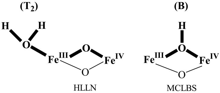
The intermediate X formed in Y122F-β2 has been the focus of many studies because it accumulates to high levels, minimizing interference from other diiron species.24 Studies of many other diiron proteins in different oxidation states indicate that the observed antiferromagnetic exchange-coupling between the Fe ions of X requires the presence of one or more oxo and/or hydroxo bridges. We previously used a combination of 1H and 2H CW and pulsed-ENDOR protocols to identify the types of protonated oxygen (OHx) species and their disposition relative to the ferric and ferryl ions of X.12,25 We considered the possible presence, either separately or jointly, of an hydroxo bridge, which we denoted B, and a terminal aqua ligand (OHx) bound to FeIII, denoted Tx (Fig 1). Analysis of this data led us to conclude that the inorganic core of X contains such a terminal aqua ligand (OHx) but not an hydroxo bridge. In addition, the data gave no evidence for an additional HxO terminally bound to FeIV, but did not rule it out. A subsequent 17O ENDOR study of X prepared, either with H217O or with 17O2 then led us to conclude that the [(HxO)FeIIIOFeIV] fragment in fact is the complete inorganic core of X.14 This interpretation has been questioned in several recent reports, but these reports do not themselves agree on the core of X. The Solomon group used RFQ magnetic circular dichroism (MCD) measurements and TD-DFT calculations to propose that the core of X has a μ-oxo/μ-hydroxo FeIII/FeIV core, but did not address the existence of terminal (HxO) (denoted MCLBS in Fig 2).10 In a more extensive series of computational studies, Noodleman and coworkers26,27 instead concluded that X possesses a di-μ–oxo FeIII/FeIV core plus a terminal (H2O) bound to FeIII (T2, denoted HLLN, in Fig 2).27
Fig 1.
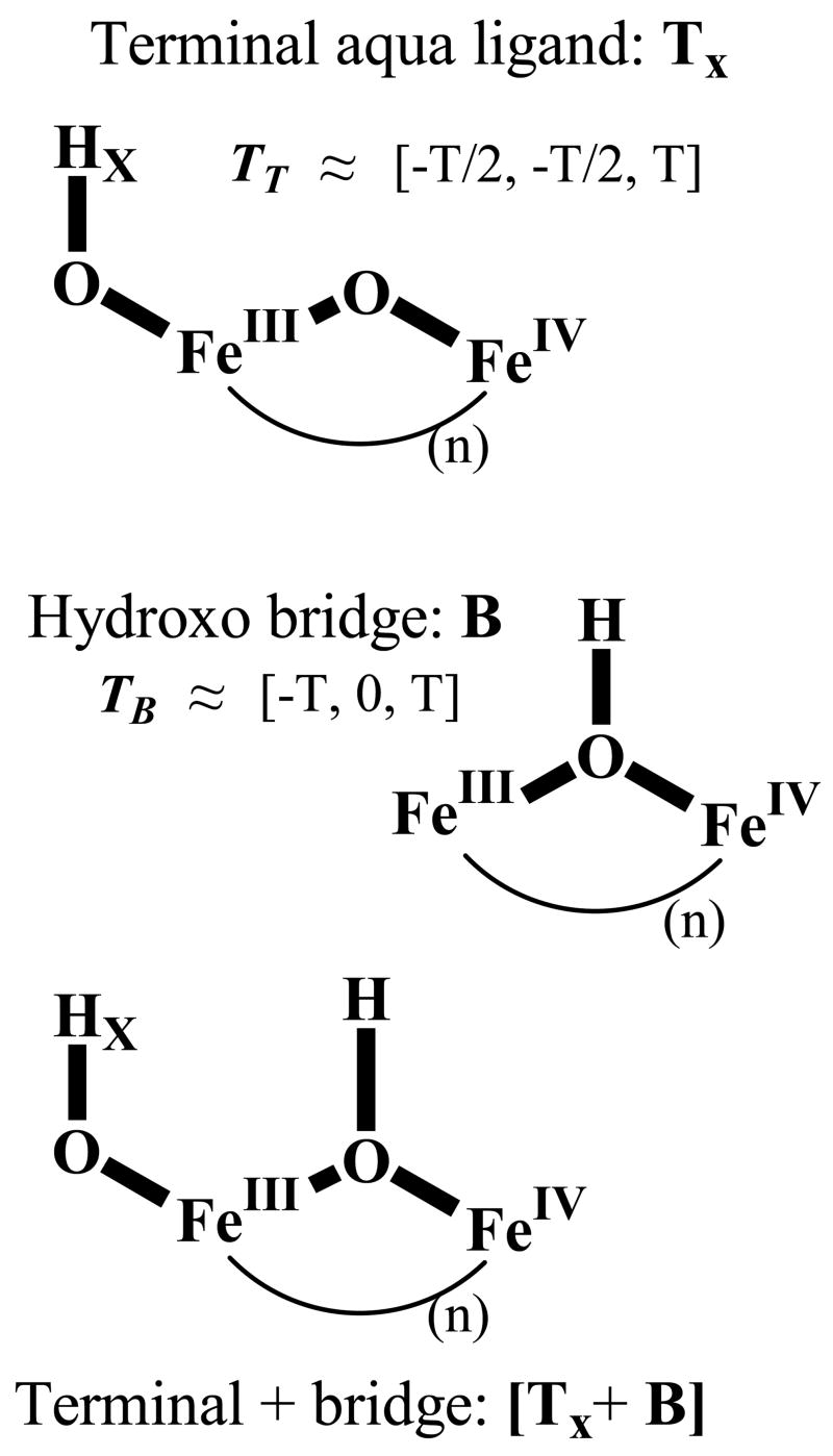
Alternate, models for exogenous ligands to X, with the portions relevant to this study in bold. Top, oxo bridge plus terminal aqua ligand (TX); middle, hydroxo bridge (B); bottom, terminal aqua plus bridge [TX+B]. Approximate characteristics of the 1,2H cluster dipolar hyperfine tensors are indicated (eqs S1–4).
Fig 2.
Inorganic cores of X models proposed by Noodleman and coworkers (HLLN)27 and by Solomon and coworkers (MCLBS),10 with the portions relevant to this study in bold.
In this report we take advantage of improvements in 35 GHz pulsed-ENDOR performance to reexamine the protonation state of the oxygenic ligands of the inorganic core of X by directly probing the exchangeable proton(s) with 2H pulsed-ENDOR spectroscopy. We further use 2H and 14N ENDOR measurements to test whether the core structure of X in the WT and Y122F-β2 variants are identical.
Materials and Methods
Samples
X in WT and Y122F β2 D2O buffer was prepared by RFQ methods in12 and stored in liquid nitrogen since 1996. 35 GHz EPR and ENDOR spectroscopy demonstrates that the signals are unchanged by this storage. The times points examined were 33 ms for X generated with WT-β2 and 610 or 1200 ms for Y122F-β2. In both cases, the amount of X is maximized at these times. A comparison of the results for the two variants thus provides insight into the role of the phenolic hydroxyl group of Y122 on the properties of X.
ENDOR Spectroscopy
Previous studies of X employed 35 GHz CW and pulsed 1,2H ENDOR spectroscopy of exchangeable hydrogenic species associated with X; in this report we discuss only pulsed 2H measurements. The recent upgrade to the 35 GHz pulsed-ENDOR spectrometer28 employed in this study has been described.29 In the text we present only 2H ENDOR spectra that were collected by the Davies (tp-T-tp/2-τ-tp-τ-echo) ENDOR sequence (RF applied during interval, T); in Supplementary Material we present both Davies and Mims (tp-τ-tp-T-tp-τ-echo)30 pulsed-ENDOR measurements. In all measurements, frequency values within the radio-frequency range chosen for the spectrum were accessed randomly (stochastic ENDOR). Signal averaging was accomplished by collecting multiples of such spectra, rather than by multiple acquisitions at each frequency within a spectrum.31 The enhanced signal/noise ratio (S/N) provided by this ‘single-point stochastic ENDOR’ approach has enabled the reassessment described herein.
The enhanced S/N had one unanticipated consequence. While samples prepared in H2O buffer previously had flat backgrounds in the 2H ENDOR region, they now reveal broad features associated with 14N that persist in the 2H spectra for enzyme in D2O. These features reproduce precisely, so many of the 2H ENDOR spectra presented here have had the background subtracted, as noted in figure legends. To demonstrate that this procedure is totally benign, we present the corresponding primary data, foreground and background together, in Supplementary Material (Fig S1).
The Davies sequence intrinsically introduces a modulation of the ENDOR intensity that varies with the hyperfine coupling, A, and must be accounted for in simulations. The Davies ENDOR response, R, is jointly dependent on the hyperfine coupling, A, and the length of the microwave pulse, tp, through the selectivity factor, η:
| (1) |
where R0 is the maximum ENDOR response.30 For fixed tp, this function suppresses the ENDOR response as A → 0, it rises to a maximum at Atp = 0.7, and then falls to zero. As a result, the 2H ENDOR spectra of X displayed here do not show features from the weakly-coupled exchangeable protons. The Mims response shows periodic maxima and minima as function of η′ = Aτ, with the first maximum at, η′ = 0.5.
A deuteron ENDOR signal for a single molecular orientation consists of a doublet centered at the Larmor frequency, νD, and split by the orientation-dependent hyperfine coupling A; spectra in this paper are plotted as Δν = ν − νD. In this report, a 2H ENDOR signal consists of a doublet centered at νD and split by AD; the additional splitting from the nuclear quadrupole interaction expected for the (I = 1) 2H nucleus is not resolved for the strongly-coupled deuteron signals discussed here. The Larmor frequency and hyperfine constants of protons and deuterons are related by the equation: νH/νD = AH/AD = gH/gD = 6.5. As discussed in detail,32–34 for a frozen solution sample, the determination of the full hyperfine tensor (and quadrupole tensor) of an interacting nucleus is achieved by obtaining a 2-D set of orientation-selective ENDOR spectra collected at multiple fields across the EPR envelope and comparing this set with simulated 2-D patterns. The ENDOR simulations were performed with the program Gensim, an enhanced version of the simulation program GENDOR.32 The Davies and Mims response factors have a major influence on the observed ENDOR response, and are incorporated into Gensim.
1,2H Hyperfine Interactions of protonated oxygenic ligands
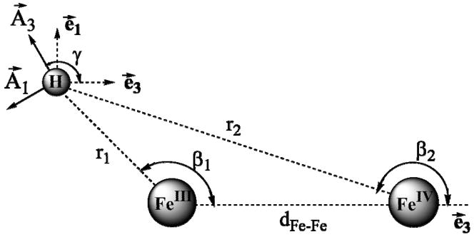
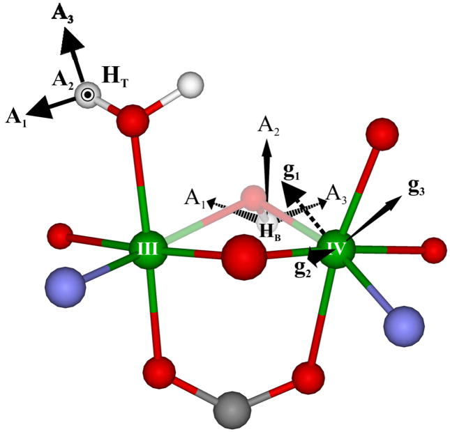
Our work12,35 has shown that the hyperfine tensor for a proton of a bridge or a terminal aqua (water/hydroxo) ligand is dominated by the through-space dipolar contribution, T, arising from with interactions with the Fe ions of the diiron center of X (A = T + aisoU; U = unit matrix). Equations have been derived to calculate the observed dipolar coupling tensor for a nucleus in an arbitrary position relative to the two Fe ions of an S = ½ spin-coupled [FeIII(S = 5/2)-FeIV(S = 2)] diiron center;12 these equations are reproduced in Supplementary Material. The principal values are functions of the cluster’s metrical parameters as defined in Supplementary Material; the component T2 lies normal to the Fe(H)Fe plane and T/A are rotated about the T2/A2 direction by the angle, γ, Fig 3 (eq S3), which also is determined by the structure. The isotropic coupling, aiso, of such protons is small or even negligible.
Fig 3.
Geometry used in calculation of cluster dipolar interaction tensor, T (eqs S1–4).
For a terminal water (or hydroxide) the dipole interaction tensor (T) with the liganding iron ion dominates the 1,2H hyperfine interaction tensor (A). It is approximately axial, T ~ [−½T, −½T, T], with the T3 axis lying close to the Fe-H vector; T ~ (7/3)gβgnβn/r13 when the ligand is bound to the ferric ion, but T ~ (−4/3)gβgnβn/r23 when it is bound to the ferryl ion. In contrast, a proton of a bridging hydroxide interacts strongly with both Fe ions and it is characterized by a nearly rhombic dipolar tensor, T ~ [−T, 0, T], with the rotation of T about the A2 direction such that A1, A3 do not point toward a specific atom.
A model-free determination of A through simulations of the experimental 2-D ENDOR field-frequency pattern gives the principal values of A and its orientation within the g tensor reference frame. As discussed in Supplementary Material, if the orientation of A is determined by the through-space dipolar interaction with the cluster Fe spins, T, then the orientation of A in the molecular (e) frame is determined (Fig 3) and through this the experimentally determined orientation of g relative to the e frame can be derived.36
Results and Discussion
EPR Spectra of X
The EPR spectra of X appear isotropic when collected at X-band, but at 35 GHz show moderately well-resolved features that permit determination of the g-tensor components. Most importantly here, this allows us to collect orientation-selective 2-D field-frequency patterns of ENDOR spectra taken at multiple fields across the EPR envelope; their analysis yields the hyperfine interaction tensors of coupled nuclei.
Alternative Models for the Identity of the Strongly-Coupled Exchangeable 1,2H of X
Our previous studies12,13 revealed 1,2H ENDOR signals from strongly-coupled exchangeable proton(s), and considered their possible association with a terminal aqua ligand (OHx) (Fig 1, top), an hydroxo bridge (Fig 1, middle), or both (Fig 1, bottom). To distinguish among these, we optimized simulations of a 2-D field-frequency pattern comprised of 1,2H ENDOR spectra taken at multiple fields across the EPR envelope of X under the assumption either of the presence of a bridging hydroxyl (B model) or of an aqua ligand terminally bound to FeIII (T model), each with a net dipolar hyperfine coupling tensor, T, to the spin-coupled iron ions given by eqs S1–4.
The geometric parameters that define the dipolar coupling calculations for the B and Tx models were chosen then as best was possible in the light of the EXAFS data available and in keeping with general bonding principles. These were used in conjunction with eqs S1–4 to generate 2-D patterns of 1,2H ENDOR spectra that optimized the agreement with experiment by constraining the calculated spectra at g1 and g3 to match experiment. Although this constraint guaranteed a qualitative similarity between the predicted 2-D patterns of the B and T models, key differences between them, primarily in the spectra between g2 and g3, led us to the T model we reported. This model required the assumption that the terminal aqua ligand had two slightly different 2H, reflecting the presence either of a terminal H2O or a two-fold disordered hydroxyl.
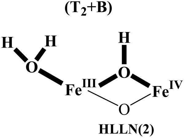
In the present study we have the advantage of also being able to predict electron-nuclear dipolar interactions for B models based on recent DFT-determined structural models of the core of X. MCLBS reported their preferred structure, a B model. HLLN reported as their preferred model a T2 structure of X (Fig 2, LLN) that has a terminal H2O but not an hydroxo bridge (for clarity, denoted T2). However they also reported the structure of a [T2+B] model, which has both types of proton, as represented by HLLN(2) in Inset 1. As discussed below, we employed the metrical parameters of these two structures as input in determining the principal values of T (Eqs S1–4) for both types of proton; these are presented in Table 1. In addition, when the two types of proton are assumed to be present simultaneously, use of the HLLN(2) structure allowed us to determine the orientation of g in the molecular (e) coordinate frame (Fig 3). We emphasize, however, that direct calculation with eqs S1–4 shows that reasonable variations to the structure of the inorganic core of X gives comparable results.
Inset 1.
Table 1.
Metrical and 2H spin Hamiltonian parameters used to calculatea the 2-D ENDOR patterns displayed in Figs. 4A and 4B
| Terminal OHX− | Bridging OH− | |||||
|---|---|---|---|---|---|---|
| Experimental | Calculatedc | Optimized | Calculatedd | |||
| (Aex)b | (Tex) | (TT) | (AB0)b | (TB0) | (TB) | |
| A1/T1(MHz) | −1.55 | −1.717 | −1.718 | −3.031 | −2.764 | −2.762 |
| A2/T2(MHz) | −1.15 | −1.317 | −1.316 | −0.948 | −0.681 | −0.681 |
| A3/T3(MHz) | 3.2 | 3.033 | 3.034 | 3.179 | 3.446 | 3.443 |
| λ | 0.132 | 0.132 | 0.604 | 0.604 | ||
| Aiso(MHz) | 0.167 | −0.267 | ||||
| r1(Å)e | 2.625 | 2.67 | ||||
| β (°) | 94.5 | 59.3 | ||||
| γ (°) | 90.0 | 50.1 | ||||
| dFeFe(Å) | 2.84 | 2.817 | ||||
Simulations employed g = [g1, g2, g3] = [2.0056, 1.9977, 1.993]. Quadrupole splitting for 2H (I = 1) are not resolved, their inclusion had no effect on simulations, so were not incorporated.
The Euler angles for Aex are α = 10.5°, β = 72.0° and γ = 0.0°. The Euler angles for AB α = 0.0°, β =115.0° and γ = 75.0°. For definition of angles, see Ref32.
Best match between Tex and T as calculated by eqs S1–4.
Calculated by slight optimization of the HLLN(2) structure.
r1, β, γ and dFeFe are defined in Fig 3.
Deuteron ENDOR of Intermediate X
Our previous study described the basic features of the 1,2H ENDOR response of X. It exhibits strongly-coupled, exchangeable 1,2H signals, 8 ≤ A (1H) ≤ 20 MHz, from protonated oxygenic ligands, plus numerous signals from more weakly-coupled 1,2H, A (1H) ≤ 8 MHz, some of which were exchangeable. In the study of the strongly-coupled 1,2H, limitations in S/N compelled us to combine 1,2H CW and pulsed measurements of X to obtain the 2-D field-frequency 1,2H ENDOR patterns for the protonated oxygenic ligands that are used to derive hyperfine tensors. With the improved S/N now available from the pulsed spectrometer we have collected full 2-D Davies pulsed 2H ENDOR patterns for these exchangeable deuteron(s) for X quenched in D2O buffer.
Experiments were performed on samples of X(WT) (Figs 4, 5, S1) and X(Y122F) (Fig S2B, S3) freeze-quenched so that the time delays after mixing are long compared to the half-time for formation of X. The 2H ENDOR response appears in an rf region that contains signals from 14N of histidine bound to the Fe ions. To enhance the ability to compare the 2H ENDOR experiment and simulation, the spectra of X(WT) in Fig 4A have had the corresponding background, collected from a sample prepared in H2O buffer, digitally subtracted. As can be seen in Fig S1 the 14N features are faithfully reproduced in foreground and background spectra, and the subtraction procedure introduces no distortions. Fig S2A shows that the 2-D 2H ENDOR patterns of X(WT) and X(Y122F) are indistinguishable, indicating that neither the mutation nor the quench delay influences this property of X.
Fig 4.
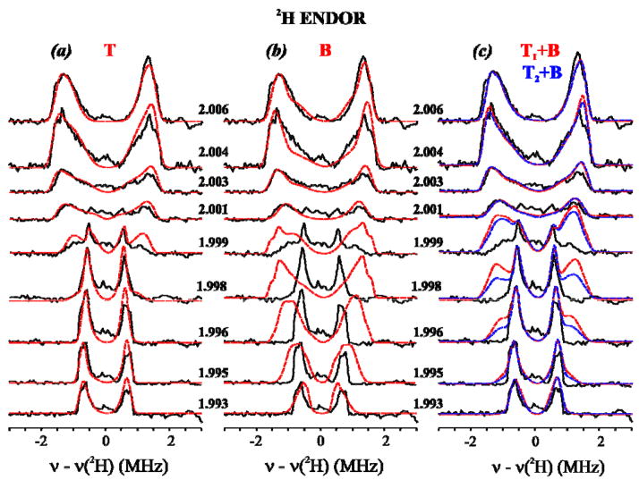
Experimental 2-D field-frequency plots of Davies 2H ENDOR spectra of X(WT) in D2O. Red and blue curves are simulations with the three models considered here (Fig 1; see text and Table 1): (a) T; (b) B, (c) [TX+B], considered here. Conditions: π-pulse length = 200 ns, τ = 600 ns, repetition time = 50 ms, MW frequency = 34.826 GHz, T = 2 K. All spectra are centered at the 2H nuclear Larmor frequency. Backgrounds have been subtracted from experimental spectra as discussed (See Materials and Methods and Supplementary Materials.).
(a) Experiment with T proton simulations overlaid. Simulation parameters (determined as described in text): g = [g1 = 2.0056, g2 = 1.9977, g3 = 1.993], A = [A1 = −1.55, A2 = −1.15, A3 = 3.2] MHz (Euler angles α = 10.5°, β = 72°, γ = 0), line widths used = 0.09 (minimum) to 0.25 (maximum) MHz.
(b) Experiment with simulations of the B proton model, optimized by including aiso. Spin Hamiltonian parameters for the bridging hydroxide (optimized); g = [g1 = 2.0056, g2 = 1.9977, g3 = 1.993], A = [A1 = −3.031, A2 = −0.948, A3 = 3.179] MHz (Euler angles α = 0.0°, β = 115.0°, γ = 75.0°), linewidths range from 0.08 (minimum) to 0.25 (maximum) MHz.
(c) Experiment with simulations of [TX+B] models: x = 1 (red), x = 2 (blue). Parameters for the simulations of terminal and the optimized bridging hydroxides: see Figs 4A, 4B and Table 1. For x = 1, the intensities of the T and B deuteron signals were added and the resultant scaled to the maximum of the experiment; for x = 2, twice the T intensity was added to the B intensity before scaling.
Fig 5.
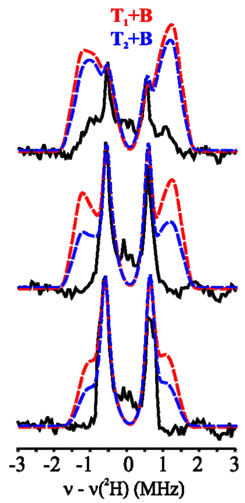
Decisive comparisons between experimental 2H-ENDOR responses for X(WT) and simulations for the [TX+B] models, as described in Fig 4: g = 1.999, 1.998 and 1.996.
Terminal (Tx) vs Bridging (B) OH
Model-free simulation of the 2-D 2H ENDOR patterns for X in D2O yielded spectra that reproduce experiment with superb fidelity, Fig 4A. These simulations employed only a single (type of) contributing deuteron whose hyperfine tensor, ATex (Table 1), has the axial character predicted for the T model of a terminal aqua ligand (Fig 1, top). The overall description matches rather well with that reported previously. However, the superb fit to the improved data of a model with a single type of terminal deuteron now implies that if this signal represents two deuterons they must be very nearly magnetically equivalent. The principal values of the experimental dipolar interaction tensor, TTex, match well with those calculated with the dipolar equations (eqs S1–4) for a terminal [HxO-FeIII] of the X diiron center. The optimized location of 2H relative to the iron ions (β1, r1) (Table 1, S1) is roughly bracketed by those of the two protons of the terminal H2O of HLLN2 (Fig 6, Table S1). However, note that a D2O with this orientation would give an ENDOR pattern in which the signals from the two deuterons are resolved, contrary to experiment.
Fig 6.
Orientation of AT, TB/AB for HT of the hypothetical HLLN(2) model of X, along with the orientation of g in the molecular frame as determined from AT and experimental simulation parameters (See Supp. Mat). TT is not shown for the other terminal proton.
To test whether the experiments could be comparably well-described by the B model, we generated an optimized 2H hyperfine tensor, ABo (Table 1), for the hydroxo bridge, as follows. We used eqs S1–4 to calculate TB for the bridging hydroxyl of the MCLBS and HLLN2 structures and performed simulations as the orientation of each was varied with respect to g. The best results were obtained when ABo included the dipolar interaction similar to that of the MCLBS hydroxyl plus a small isotropic component (Table 1). These optimized simulations are overlaid on experiment in Fig 4B. As in our previous study, these simulations based on an optimized B model for the exchangeable deuteron reproduce the spectra at the edges of the EPR envelope (g1 and g3), but are poor at fields away from the edges, particularly at fields between g2 and g3, We thus confirm the previous conclusion that the observed 1,2H signals cannot be described by assuming that the only protonated oxygenic ligand in the core of X is an hydroxo bridge.
As the superb simulations of the pulse 2H ENDOR data in Fig 4A involve a single type of 2H associated with a terminal aqua ligand, they are most simply assigned to a terminal hydroxyl with a single major (tier 1) orientation. The requirement of systematic variations of the ENDOR linewidth further suggests a modest distribution in position of the deuteron (tier 2 substates). However, we cannot exclude the possibility of a H2O ligand whose two protons accidentally are equivalent and indistinguishable within the resolution of our spectra, although this seems less likely to us. The recent DFT study of HLLN inferred the presence of a water ligand to FeIII, while the study of MCLBS does not address the issue.
[Tx+B], Terminal Plus Bridging?
Could X, however, contain both T and B protons, the [Tx+B model of Fig 1, as might be inferred from the MCLBS study? In our earlier study we had in fact considered this question by looking for 1,2H ENDOR intensity that is not accounted for by the T model. A comparison of simulations for the T and B models (Fig 1) suggested that the optimal fields to look for intensity from a B deuteron would be in the field range from ~ g2–g3, where the T deuteron(s) had their smallest splitting and calculated B spectra were appreciably broader. Although we recognized that the broader signals from a B deuteron would presumably be less intense than the narrower signals from the T deuteron(s), no additional signals were detected in spectra where extensive signal averaging had produced good signal/noise ratios. We thus concluded that there is no hydroxo bridge.
The improved data reported here has allowed us to reexamine this possibility, and in doing so we have adopted a more ‘directed’ approach. In the previous study we were forced to look for signals from a B deuteron without knowing what fields and frequencies were best to find them, or how intense they might be if present. The present study removes this limitation. We have used multiple approaches to calculate the spectra to be expected if both T and B deuterons were present and have compared them with experiment.
To predict the ENDOR response for a hypothetical X with both T and B deuterons ([Tx+B], Fig 1) we assumed the presence of either one or two T deuterons described by ATex (Table 1), namely either a terminal hydroxo (T1) or a terminal water (T2 in Fig 2) that has two magnetically equivalent deuterons. As the most straightforward approach to describing a B deuteron, we assigned to B the hyperfine tensor AB0, as defined above (Table 1), and calculated the 2-D field-frequency patterns expected if both T and B deuterons were present, Fig 4C. To ensure that we have given the best chance for this model to succeed, we minimized the predicted detectability of B by employing for the T deuteron the field-dependent linewidth used in Fig 4A, while using for B a linewidth at all fields that equaled the largest linewidth found for the T deuteron(s) at any field (the value near g1), rather than the optimized linewidth for each field as used in Fig 4B. Fig 4C displays the resulting composite 2-D 2H ENDOR pattern calculated for models with both x = 1 and x = 2 protons on the terminal OHX, along with the B deuteron, [T1+B] and [T2+B] models respectively, each overlaid onto the experimental 2H ENDOR pattern for X(WT); Fig 5 separately presents the experimental and calculated spectra for fields at which the presence of a B deuteron would be most obvious. In fact, it is obvious that none of the intensity predicted for a B deuteron is present in the experimental spectra.
As an alternate means of simulating the [T1 (or) T2 +B] model of X we employed the HLLN2 structure for X (Fig 6) in a recently developed simulation approach.36 As shown in the figures, HLLN2 incorporates a H2O terminally bound to FeIII, an hydroxo bridge that carries the B proton, as well as an oxo bridge. To calculate the 2H ENDOR spectra expected for this B proton, we assigned the experimentally determined T-proton hyperfine tensor, ATex, first to one of the deuterons of the terminal H2O of HLLN2 (eg., HT of Fig 6) then to the other, in each case taking ATex as coaxial with TT calculated with eqs S1–4; then we used our the experimentally determined orientation of ATex relative to g to fix the orientation of g in the molecular frame (Fig 6). Once this was known, we could use eqs S1–4 to calculate the dipolar interaction for the B deuteron, TB, from the HLLN(2) structure and to compute the 2-D patterns of 2H ENDOR spectra to be expected if both types of deuteron were present.
In all these computations, as shown in Figs S4, S5, the simulations predict additional 2H ENDOR intensity associated with B that would be even more obvious and readily detected than if a bridging proton had the optimized hyperfine tensor, AB, Fig 5. No such intensity is seen in the experiment.
A technical observation about the experiments and simulations also is of interest. Each of the ENDOR simulations of Figs 4, 5 is a ‘statistical/geometric’ sum of the contributions from the subset of orientations that contributes to the EPR spectrum at the g-value of observation.32 In such a simulation, the integrated ENDOR intensity of a T and B deuteron would be equal. As the B spectrum is broader and is calculated with a greater component ENDOR linewidth, if ‘statistical/geometric’ considerations were all that were important for determining intensities, the relative intensities of features associated exclusively with B would be much less than those of the T proton, making the detection of B harder than it is seen to be in Fig 5. However, the sharp T doublet has a smaller hyperfine coupling and is suppressed to a greater degree by the Davies ENDOR response (eq 1). Thus, curiously, while the suppression effect reduces the overall S/N of the spectra, it helps enable us to state with confidence that X does not contain a B proton in addition to the T proton(s).
In short, the absence in the spectra of any of the unexplained features that would be required for the proton of a μ–OH) bridge rules out the presence of such a moiety, either alone or in addition to the FeIII-bound terminal aqua ligand (HxO): only the latter is present (TX model ofFig 1), in agreement with our proposal of over a decade ago.12
The model for the inorganic core of X favored by HLLN agrees with our earlier proposal and current conclusion regarding the protonation state of the X core (Fig 2), whereas the recent MCD measurements of MCLBS instead were interpreted to favor an hydroxo bridge. A critical comparison of the two methods is thus in order. Firstly, the present ENDOR measurements directly interrogate the protonated oxygenic ligands of X, whereas optical methods only indirectly infer the sites of protonation. Furthermore, ENDOR is insensitive to diamagnetic forms of RNR that may be present in sample preparations, whereas the optical methods include signals from all states of RNR. Secondly, the electronic structure assignments of MCLBS and the corresponding assignment of a μ-hydroxo bridge derive from their assignment of all three d-d transitions to the d-π manifold of X, based in part on the conclusion that the splittings are too large to be associated with a bis-μ-oxo structure. The more extensive computations of HLLN, associated with a more realistic model of protein ligands to the diiron center, lead them to assign the optical bands differently, thereby leading them to reject the HLLN structure that has no μ-hydroxo bridge, Fig 2. Lastly, for completeness, we suggest that a more rigorous test of the new sample preparation procedure of MCLBS, which differ from that used in all previous RFQ studies12–15,19,37,38 would be welcome. The MCD study involved freeze-quenching by spraying into liquid nitrogen, rather than liquid pentane, which gives longer freezing times. Also, high concentrations of glycerol were added at −30°C as a glassing agent subsequent to freeze-quenching. Although MCLBS carried out 9 GHz EPR experiments to test whether X prepared in their procedure is the same as in the samples prepared previously, the signal of X appears isotropic at X band and is not a particularly sensitive test for subtle structural differences that might occur.
Other 1,2H ENDOR signals and the possibility of a HxO bound to FeIV
In our earlier work we observed non-exchangeable 1H ENDOR signals from the protein matrix, to be associated with ligands to the diiron center and nearby amino acids. In addition, we saw weakly-coupled exchangeable 2H signals, presumably from histidine-imidazole, amino/amido N-H, etc. We found no evidence for exchangeable 2H ENDOR signals that would be associated with a HxO bound to FeIV. Combining this with the subsequent failure to find a 17O signal from such a species, we concluded that none was present. In the present study we also reconsidered the possibility of a HxO bound to FeIV. Such a proton is predicted (eqs S1–4) to have a roughly rhombic dipolar tensor with maximum 2H tensor components of ~ 2 MHz. To test for signals from such a proton we collected both 2H Mims (Fig S6) and 2H ‘soft (tp = 200 ns)’ Davies pulsed- ENDOR spectra (Figs 4, S1) but neither gave any evidence for 1,2H ENDOR intensity for such a proton. Thus, the present effort is consistent with our earlier conclusion, as well as with the computations of HLLN.
Possible Effects of the Y122F Mutation
The 2-D patterns of 2H ENDOR spectra of X(WT) and X(Y122F) are identical, within error (Fig S2A), as are the hyperfine tensors determined by simulating those patterns (Table 1; Figs 4A and S2B). To search for other possible influences of the mutation we collected 2-D field-frequency plots of 14N ENDOR spectra for X(WT) and X(Y122F). Fig S3 shows that these plots for the two likewise are indistinguishable.
Conclusions
In this report we take advantage of improvements in 35 GHz pulsed ENDOR signal/noise to reexamine the protonation state of the oxygenic ligands of inorganic core of X directly by probing the exchangeable protons of X(WT) and X(Y122F) with 2H pulsed-ENDOR spectroscopy. The 2-D pattern of Q-band 2H ENDOR spectra collected for the strongly-coupled exchangeable proton(s) of X(WT and Y122F) are indistinguishable (Fig S2A), and the same is true for 14N ENDOR measurements of histidyl ligands bound to Fe, together indicating that the Y122F mutation does not alter the properties of X.
Simulations of the 2H 2D-field-frequency ENDOR patterns, Figs 4A, S2B, of X show that the exchangeable proton/deuteron signals belong to the proton of a terminal aqua ligand bound to FeIII (Fig 1, TX-model), likely an hydroxo ligand. Simulations based on both the B and [TX+B] models (Figs 4B, 4C, S4 and S5) completely fail to reproduce the data, demonstrating that X does not contain an hydroxo bridge, either alone (B) or with a terminal aqua ligand [TX+B]. The measurements further support the conclusion that there is no aqua ligand bound to FeIV. Overall, these findings thus establish that the inorganic core of X does not include a μ-hydroxo bridge, and does contain the [(HxO)FeIIIOFeIV] fragment that defines the TX-model (Fig 1; top). We shall next use the enhanced 35 GHz pulsed-ENDOR capabilities to revisit the question of whether X contains the second oxo bridge of a diamond core, as favored by both HLLN and MCLBS, by exploring the fate of the two atoms of dioxygen and the incorporation of solvent O through direct interrogation of those atoms by 17O ENDOR spectroscopy.
Supplementary Material
Acknowledgments
The authors would like to express their gratitude towards C. E. Davoust for his technical support and to the NIH (Grants HL 13531 (B. M. H); GM 29595 (J. S.)).
Footnotes
Supporting Information Available: Calculation of dipolar interactions (eqs S1–S4); Figs S1–S6; Table S1
References
- 1.Eklund H, Uhlin U, Farnegardh M, Logan D, Nordlund P. Progress in Biophysics & Molecular Biology. 2001;77:177–268. doi: 10.1016/s0079-6107(01)00014-1. [DOI] [PubMed] [Google Scholar]
- 2.Solomon EI, Brunold TC, Davis MI, Kemsley JN, Lee SK, Lehnert N, Neese F, Skulan AJ, Yang YS, Zhou J. Chem Rev (Washington, DC, U S) 2000;100:235–349. doi: 10.1021/cr9900275. [DOI] [PubMed] [Google Scholar]
- 3.Nordlund P, Eklund H. Curr Opin Struct Biol. 1995;5:758–766. doi: 10.1016/0959-440x(95)80008-5. [DOI] [PubMed] [Google Scholar]
- 4.Feig AL, Lippard SJ. Chem Rev (Washington, DC, U S) 1994;94:759–805. [Google Scholar]
- 5.Licht S, Stubbe J. In: Mechanistic investigations of ribonucleotide reductases; Comprehensive Natural Product Chemistry. Poulter C Dale., editor. Vol. 5. Elsevier Science; New York: 1999. pp. 163–203. [Google Scholar]
- 6.Stubbe J, Riggs-Gelasco P. Trends Biochem Sci. 1998;23:438–443. doi: 10.1016/s0968-0004(98)01296-1. [DOI] [PubMed] [Google Scholar]
- 7.Stubbe J, van der Donk WA. Chem Rev (Washington, DC, U S) 1998;98:705–762. doi: 10.1021/cr9400875. [DOI] [PubMed] [Google Scholar]
- 8.Atkin CL, Thelander L, Reichard P, Lang G. J Biol Chem. 1973;248:7464–7472. [PubMed] [Google Scholar]
- 9.Larsson A, Sjöeberg BM. EMBO J. 1986;5:2037–2040. doi: 10.1002/j.1460-2075.1986.tb04461.x. [DOI] [PMC free article] [PubMed] [Google Scholar]
- 10.Mitic N, Clay MD, Saleh L, Bollinger JM, Solomon EI. J Am Chem Soc. 2007;129:9049–9065. doi: 10.1021/ja070909i. [DOI] [PMC free article] [PubMed] [Google Scholar]
- 11.Riggs-Gelasco PJ, Shu L, Chen S, Burdi D, Huynh BH, Que L, Jr, Stubbe J. J Am Chem Soc. 1998;120:849–860. [Google Scholar]
- 12.Willems JP, Lee HI, Burdi D, Doan PE, Stubbe J, Hoffman BM. J Am Chem Soc. 1997;119:9816–9824. [Google Scholar]
- 13.Burdi D, Sturgeon BE, Tong WH, Stubbe J, Hoffman BM. J Am Chem Soc. 1996;118:281–282. [Google Scholar]
- 14.Burdi D, Willems J, Riggs-Gelasco P, Antholine W, Stubbe J, Hoffman B. J Am Chem Soc. 1998;120:12910–12919. [Google Scholar]
- 15.Ravi N, Bollinger JM, Jr, Huynh BH, Edmondson DE, Stubbe J. J Am Chem Soc. 1994;116:8007–8014. [Google Scholar]
- 16.Bollinger JM, Jr, Tong WH, Ravi N, Huynh BH, Edmondson DE, Stubbe J. J Am Chem Soc. 1994;116:8024–8032. [Google Scholar]
- 17.Bollinger JM, Jr, Edmondson DE, Huynh BH, Filley J, Norton JR, Stubbe J. Science. 1991;253:292–298. doi: 10.1126/science.1650033. [DOI] [PubMed] [Google Scholar]
- 18.Bollinger JM, Jr, Tong WH, Ravi N, Huynh BH, Edmondson DE, Stubbe J. J Am Chem Soc. 1994;116:8015–8023. [Google Scholar]
- 19.Sturgeon BE, Burdi D, Chen S, Huynh BH, Edmondson DE, Stubbe J, Hoffman BM. J Am Chem Soc. 1996;118:7551–7557. [Google Scholar]
- 20.Logan DT, Su XD, Aberg A, Regnstrom K, Hajdu J, Eklund H, Nordlund P. Structure. 1996;4:1053–1064. doi: 10.1016/s0969-2126(96)00112-8. [DOI] [PubMed] [Google Scholar]
- 21.Wei P-p, Skulan AJ, Mitic N, Yang Y-S, Saleh L, Bollinger JM, Jr, Solomon EI. J Am Chem Soc. 2004;126:3777–3788. doi: 10.1021/ja0374731. [DOI] [PubMed] [Google Scholar]
- 22.Nordlund P, Eklund H. J Mol Biol. 1993;232:123–164. doi: 10.1006/jmbi.1993.1374. [DOI] [PubMed] [Google Scholar]
- 23.Nordlund P, Aberg A, Eklund H. Biochemistry Soc Trans. 1993;21:735–738. doi: 10.1042/bst0210735. [DOI] [PubMed] [Google Scholar]
- 24.Tong W, Burdi D, Riggs-Gelasco P, Chen S, Edmondson D, Huynh BH, Stubbe J, Han S, Arvai A, Tainer J. Biochemistry. 1998;37:5840–5848. doi: 10.1021/bi9728811. [DOI] [PubMed] [Google Scholar]
- 25.Willems J-P, Lee H-I, Burdi D, Doan PE, Stubbe J, Hoffman BM. In: ACS Advances in Chemistry. Solomon E, Hodgson K, editors. American Chemical Society; Washington D.C: 1998. pp. 2–15. [Google Scholar]
- 26.Han WG, Liu T, Lovell T, Noodleman L. Inorg Chem (Washington, DC, U S) 2006;45:8533–8542. doi: 10.1021/ic060566+. [DOI] [PubMed] [Google Scholar]
- 27.Han WG, Liu T, Lovell T, Noodleman L. J Am Chem Soc. 2005;127:15778–15790. doi: 10.1021/ja050904q. [DOI] [PubMed] [Google Scholar]
- 28.Davoust CE, Doan PE, Hoffman BM. J Magn Reson. 1996;119:38–44. [Google Scholar]
- 29.Zipse H, Artin E, Wnuk S, Lohman GJS, Martino D, Griffin RG, Kacprzak S, Kaupp M, Hoffman B, Bennati M, Stubbe J, Lees N. J Am Chem Soc. 2008 doi: 10.1021/ja806693s. In Press. [DOI] [PMC free article] [PubMed] [Google Scholar]
- 30.Fan C, Doan PE, Davoust CE, Hoffman BM. J Magn Res. 1992;98:62–72. [Google Scholar]
- 31.Epel B, Arieli D, Baute D, Goldfarb D. J Magn Reson. 2003;164:78–83. doi: 10.1016/s1090-7807(03)00191-5. [DOI] [PubMed] [Google Scholar]
- 32.Hoffman BM, DeRose VJ, Doan PE, Gurbiel RJ, Houseman ALP, Telser J. Biol Magn Reson. 1993;13(EMR of Paramagnetic Molecules):151–218. [Google Scholar]
- 33.Hoffman BM. Acc Chem Res. 2003;36:522–529. doi: 10.1021/ar0202565. [DOI] [PubMed] [Google Scholar]
- 34.Hoffman B. Proc Natl Acad Sci U S A. 2003;100:3575–3578. doi: 10.1073/pnas.0636464100. [DOI] [PMC free article] [PubMed] [Google Scholar]
- 35.DeRose VJ, Liu KE, Lippard SJ, Hoffman BM. J Am Chem Soc. 1996;118:121–134. [Google Scholar]
- 36.Lees NS, McNaughton RL, Gregory WV, Vela J, Holland PL, Hoffman BM. J Am Chem Soc. 2008;130:546–555. doi: 10.1021/ja073934x. [DOI] [PubMed] [Google Scholar]
- 37.van der Donk WA, Stubbe J, Gerfen GJ, Bellew BF, Griffin RG. J Am Chem Soc. 1995;117:8908–8916. [Google Scholar]
- 38.Bollinger JM, Jr, Tong WH, Ravi N, Huynh BH, Edmondson DE, Stubbe J. In: Methods Enzymol. Klinman JP, editor. Academic Press; New York: 1995. p. 258. [DOI] [PubMed] [Google Scholar]
- 39.Additional solutions are closely related and need not be considered separately
Associated Data
This section collects any data citations, data availability statements, or supplementary materials included in this article.


