Abstract
Background
Compared with fluoroscopy, the current imaging standard of care for guidance of electrophysiology procedures, magnetic resonance imaging (MRI) provides improved soft-tissue resolution and eliminates radiation exposure. However, because of inherent magnetic forces and electromagnetic interference, the MRI environment poses challenges for electrophysiology procedures. In this study, we sought to test the feasibility of performing electrophysiology studies with real-time MRI guidance.
Methods and Results
An MRI-compatible electrophysiology system was developed. Catheters were targeted to the right atrium, His bundle, and right ventricle of 10 mongrel dogs (23 to 32 kg) via a 1.5-T MRI system using rapidly acquired fast gradient-echo images (≈5 frames per second). Catheters were successfully positioned at the right atrial, His bundle, and right ventricular target sites of all animals. Comprehensive electrophysiology studies with recording of intracardiac electrograms and atrial and ventricular pacing were performed. Postprocedural pathological evaluation revealed no evidence of thermal injury to the myocardium. After proof of safety in animal studies, limited real-time MRI-guided catheter mapping studies were performed in 2 patients. Adequate target catheter localization was confirmed via recording of intracardiac electrograms in both patients.
Conclusions
To the best of our knowledge, this is the first study to report the feasibility of real-time MRI-guided electrophysiology procedures. This technique may eliminate patient and staff radiation exposure and improve real-time soft tissue resolution for procedural guidance.
Keywords: electrophysiology, magnetic resonance imaging, magnetic resonance imaging, interventional
Catheter guidance in electrophysiology procedures is currently performed via fluoroscopy guidance. The inherent patient and staff radiation exposure and poor visualization of anatomic structures with fluoroscopy limit its desirability for guidance of complex ablation procedures. Electroanatomic systems with image integration have improved soft-tissue delineation during fluoroscopic guidance but remain limited because of inaccuracies in image acquisition and registration.1
Magnetic resonance imaging (MRI) has been shown to be useful for tissue and lesion visualization,2 arrhythmic substrate identification,3–5 and performance of invasive cardiac procedures.6,7 Importantly, a recent animal study has demonstrated the feasibility of mapping and pulmonary vein ablation with preprocedural MRI images and MRI-tracked catheters.8 However, catheter guidance by real-time MRI may be limited by catheter heating,9 current induction,10 image distortion,11 and electromagnetic signal interference.12
The objective of the present study was to test the feasibility of performing electrophysiology studies via real-time MRI guidance. Performance of catheters visualized by metallic component MRI artifacts (passive)13 or with MRI signal received by the catheter (active)14 also was assessed. After proof of safety in animal models, clinical feasibility was subsequently assessed in patients.
Methods
MRI-Compatible Components
Passive and active prototype catheters were developed for performing real-time MRI-guided electrophysiology procedures. The passive tracking catheter used in the right atrial and His bundle target positions of the animal studies had a woven Dacron body, copper wires, and 4-mm platinum electrodes (7F, Bard Electrophysiology, Lowell, Mass). The passive tracking catheter used in the phantom heating study and the human studies had a polyether block amide plastic body, copper wires, and 4-mm-tip and 2-mm-ring platinum electrodes (7F, IBI-1000, Irvine Biomedical Inc, Irvine, Calif; Investigational Device Exemption No. G010093). Both passive catheters are recognized on MRI by a local (≈1 mm) susceptibility artifact surrounding the electrode. The active tracking catheter (woven Dacron body, copper wires, copper electrodes, 10F) uses a 64-MHz loop antenna extending along the entire catheter body from which MRI signal is received, thus increasing signal intensity along the catheter body.14 The active catheter was used at the right ventricular target position of the animal studies.
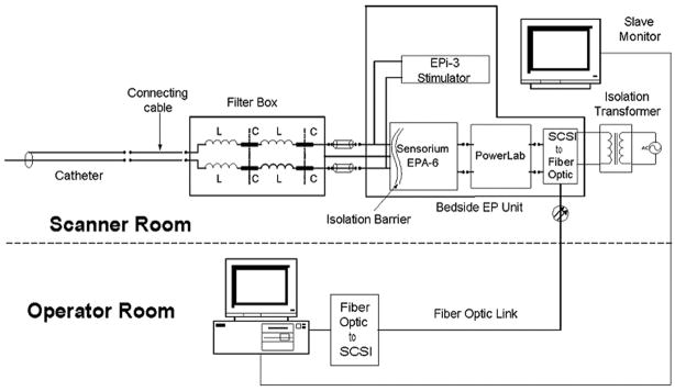
Custom shielding and filtering hardware for the catheters, data acquisition system, and stimulator were developed (Figure 1). Images were transferred to a workstation (Octane, Silicon Graphics, Sunnyvale, Calif) for manipulation and image display in the control room and a slaved monitor at the procedure table. Electrograms were passed through several levels of filtering. Low-pass radiofrequency filters (1-μhenry inductors, 1500-pF capacitors) in a 2-stage configuration were used to substantially reduce the 64-MHz radiofrequency signal from the MRI scanner to protect electronics and to mitigate catheter heating. The output was then applied to a series of active filters with a sixth-order, Chebyshev (1-dB ripple), low-pass filter (300 Hz) and a second-order, Chebyshev (1-dB ripple), high-pass filter (30 Hz), followed by a 60-Hz notch filter. The active filters reduced gradient signal–induced noise and limited the bandwidth of intracardiac electrograms to those typically used in electrophysiology studies. Signals were then displayed within the MRI suite with the custom data acquisition system.
Figure 1.
Schematic of the MRI-compatible pacing and electrogram acquisition system. The system consists of a nonmagnetic filter box that rejects the 64-MHz imaging frequency from the MRI scanner. The preamplifier is a Sensorium EPA-6 16 channel amplifier module with clinical-grade isolation. An AD Instruments PowerLab converter digitizes the output from the EPA-6. Digital data are sent to the data acquisition computer through the fiberoptic link, which forms an additional isolation barrier. The EPI-3 stimulation unit provides pacing output and is a clinical-grade unit. Electrograms are displayed in real time for the electrophysiologist via the slave monitor in the procedure suit. Additional isolation is provided by the clinical-grade isolation transformer and the fiberoptic link from the electronics inside and outside the MRI scanner suite. SCSI indicates Small Computer System Interface.
Magnetic Resonance Imaging
A 1.5-T (Magnetom Avanto, Syngo MR B13, Siemens Medical Systems, Erlangen, Germany) MRI scanner was used. Receiver coils included a 6-channel-body phased-array coil and the active catheter targeted to the right ventricle in animal experiments. The catheter receiver coil provided visual artifact for improved catheter visualization but no data for image reconstruction.
A fast gradient-recalled-echo (GRE) sequence was used to obtain standardized views (repetition time, 10 ms; echo time, 4.4 ms; flip angle, 20°; field of view, 24 to 30 cm; slice thickness, 10 mm; matrix, 256×96) before real-time sequences for catheter navigation. The Siemens (Siemens Medical Systems) commercially available real-time navigation interface was used for active plane manipulation. Real-time images were acquired as 2-dimensional fast GRE sequences with typical parameters: repetition time, 2.3 to 5.3 ms; echo time, 1.2 to 1.5 ms; flip angle, 10° to 40°; field of view, 24 to 38 cm; slice thickness, 10 mm; matrix, 256×128; and frame rate, ≈5 images per second. Planes could be manipulated by rotating or advancing along the x, y, and z planes. The estimated specific absorption rate (SAR) of sequences was minimized by increasing the repetition time or field of view and/or decreasing the flip angle or acquisition bandwidth while maintaining adequate image quality for catheter guidance.
Phantom Heating Study
Phantom studies were performed with a 20×20×50-cm acrylic box filled with 10 kg half-normal saline in the MRI scanner bore. The Investigational Device Exemption–approved passive tracking catheter was positioned in the phantom and connected to the radiofrequency-filtered recording system. Fiberoptic temperature gauges (FISO Technologies Inc: model FOT-M; accuracy, 0.05°C/60 ms; range, 20°C to 85°C) were attached to the catheter at the tip and ring electrodes and the proximal portion of the catheter body. Twenty-seven different permutations of catheter shapes (loop/straight) and catheter positions within the scanner bore (5-cm axial/longitudinal intervals from the scanner bore center) were tested using standard and worst-case-scenario GRE MRI sequences (SAR, up to 4 W/kg). Temperatures were recorded in 0.4-second increments for 180 seconds after scan initiation or longer if the temperature had not reached a plateau.
Animal Experiments
Our Institutional Animal Care and Use Committee approved the animal protocol. Ten adult mongrel dogs (23 to 32 kg) were studied. Animals were premedicated with intravenous thiopental (17.5 mg/kg) to achieve adequate sedation for endotracheal intubation. Each animal was then anesthetized with 1% to 2% isoflurane and mechanically ventilated (Narkomed Anesthesia System, Dragar Medical, Lübeck, Germany) with 100% supplemental oxygen. Using standard cutdown techniques, we placed introducer sheaths into the right femoral (8F and 10F) and left femoral (10F) veins and the right femoral artery (6F). Cardiac telemetry, pulse oximetry, and arterial blood pressure were monitored continuously. Catheters were then inserted into the femoral vein sheaths and guided via MRI along the inferior vena cava to target positions in the right atrium, His bundle, or right ventricular apex. To achieve consistency, all studies incorporated an active catheter at the right ventricular apex and passive catheters at the bundle of His and right atrium, and time to catheter placement was measured from the introduction of the catheter tip into the sheath to the recording of the electrogram at the intended target. With the animal positioned in the bore of the MRI scanner, the ability to record intracardiac electrograms and pace the right atrium and ventricle was assessed.
At the end of each experiment, animals were euthanized with pentobarbital and potassium chloride, and postmortem catheter positioning was confirmed with direct visualization after thoracotomy. In each animal, catheter positioning in the right atrium and right ventricle was confirmed visually. His catheter positioning was grossly assessed via localization of the catheter at the high tricuspid annulus. The right atrium, ventricle, and interventricular groove were inspected for evidence of thrombus and myocardial injury.
Human Studies
Our Institutional Review Board approved the protocol for catheter manipulation and electrogram measurement in the MRI environment. Two patients were enrolled after informed consent was obtained. The patients were transitioned to the MRI scanner after undergoing standard fluoroscopy-guided ablation of typical atrial flutter. The Investigational Device Exemption–approved passive tracking catheter was connected to the MRI-compatible pacing and electrogram acquisition system as detailed in Figure 1. The catheter was advanced through the right femoral venous (8F, SR-0 [Daig], St Jude Medical, St Paul, Minn) long sheath positioned in the right atrium for the initial fluoroscopy-guided procedure. Real-time sequences (detailed in the MRI methodology section) were used to guide catheter movement within the right atrium and ventricle and to the cavotricuspid isthmus. Catheter positioning was confirmed by intracardiac electrogram recordings.
Statistical Analysis
Time to catheter positioning for active versus passive catheters was compared by use of the 2-tailed Wilcoxon rank-sum test. Values of P<0.05 were considered significant. Intracardiac electrogram signal-to-noise ratio (SNR) was calculated as the signal (peak to trough atrial or ventricular electrogram) voltage to the (diastolic interval) root mean square noise ratio for each signal-signal interval and averaged over 30 beats for the window of interest.15
The authors had full access to and take full responsibility for the integrity of the data. All authors have read and agree to the manuscript as written.
Results
Phantom Heating Study
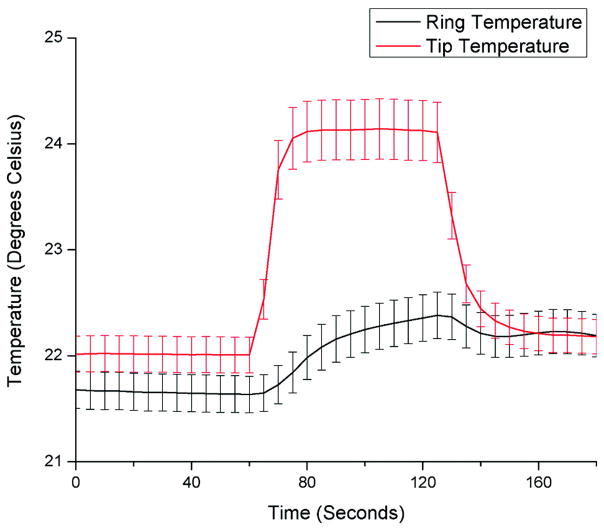
Catheter heating was found to be higher at the tip electrode compared with the ring electrode and <1°C at the proximal catheter body in all cases. The worst-case-scenario GRE MRI sequence (SAR, 4 W/kg) resulted in up to 6°C temperature rises at the tip electrode when placed at the lateral edge of the scanner. The mean temperature as a function of time for all experiments (including high-SAR sequences) is summarized in Figure 2. However, standard GRE sequences resulted in <2°C temperature rises at all measuring points along the catheter.
Figure 2.
Mean temperature at the tip and ring electrodes of the passive tracking catheter in 5-second increments for 27 different phantom test permutations in catheter shape, catheter position, and MRI sequences with worst-case-scenario SAR up to 4 W/kg. Error bars reflect the SEM.
In Vivo Animal Studies
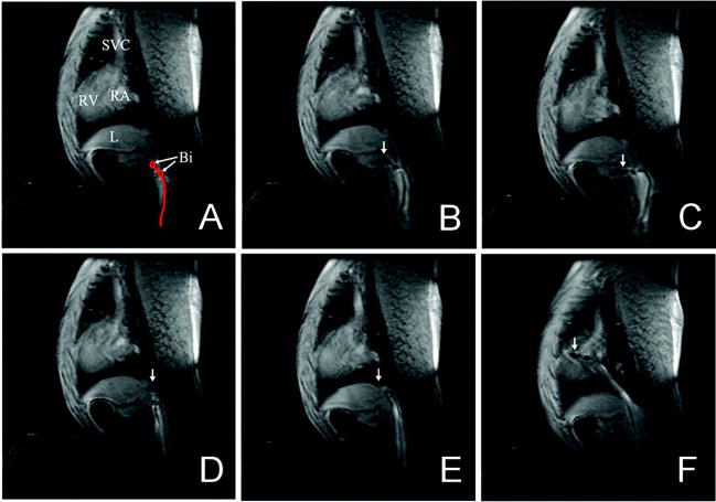
All catheters were successfully positioned at their intended target positions as confirmed by intracardiac electrograms and follow-up pathological examination (Figure 3). Average times to catheter positioning for the right atrial, His bundle, and right ventricular target sites were 169.5±102.5, 447.1±363.5, and 127.3±53.7 seconds, respectively. Postmortem examination revealed small (circular; 3 and 5 mm in radius) endocardial hemorrhages in 2 animals. Both hemorrhages were near the position of passive catheter tips on the ventricular septum just beyond the tricuspid annulus. There was no evidence of thermal tissue injury, and histopathology of the 2 sites with evidence of gross catheter trauma revealed no contraction band necrosis. Neither animal had any evidence of conduction system compromise or hemodynamic instability during the procedure.
Figure 3.
Real-time guidance of a passive catheter to the His bundle position in the canine model. A, Catheter bipolar electrodes (Bi) are shown in the inferior vena cava. B, The catheter is advanced, with tip (arrow) entering hepatic vein. C, Catheter buckling as a result of advancement into a hepatic vein. D, The catheter tip is withdrawn into the inferior vena cava. E, The catheter tip is advanced beyond the hepatic vein branch in the inferior vena cava. F, The catheter tip is advanced to the tricuspid annulus. SVC indicates superior vena cava; L, liver; RV, right ventricle; and RA, right atrium.
Passive Versus Active Catheter Tracking
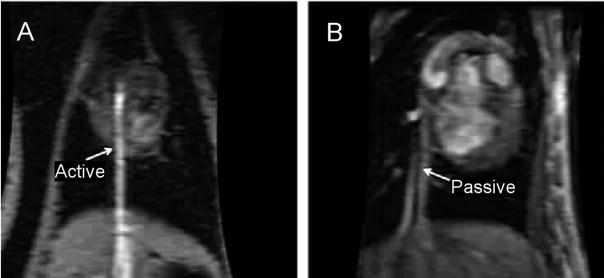
In the interactive real-time sequence, an initial imaging plane is prescribed and then actively manipulated to localize or follow the catheter. When the catheter tip was not visualized in the scanning plane, catheter movement was halted, and a new real-time plane was selected. Active catheters were easier to localize on MRI (Figure 4A) and required a median of 2 initial real-time imaging planes for catheter tip localization. In contrast, localization of the passive tracking catheters (Figure 4B) required a median of 5 initial real-time imaging planes. Time to target catheter positioning was not significantly different between the passive and active catheters (P= 0.16).
Figure 4.
Difference in visibility of active (capable of receiving MRI signal) and passive catheters on MRI images of the canine model. A, The active catheter is shown advancing through the inferior vena cava to the right ventricle. The active (bright) signal created by the catheter helps to identify its position within the image. B, The passive catheter is shown advancing through the inferior vena cava to the right ventricle. Passive visualization uses the signal void created by the catheter body or local susceptibility artifact of the platinum electrode to identify the catheter position within the image.
Intracardiac Electrogram Recording and Pacing
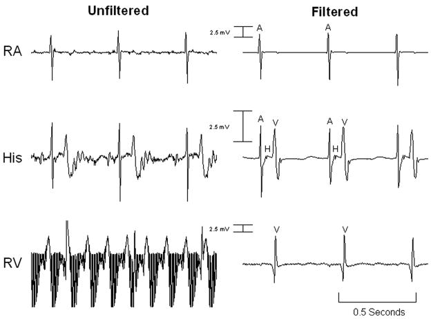
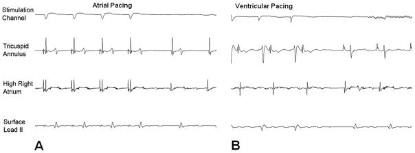
After successful catheter positioning, electrophysiology studies were performed in all animals. Recording of intracardiac intervals was performed entirely within the MRI scanner (Figure 5). The filtered atrial (passive catheter) electrogram SNR was 230.6 compared with the unfiltered SNR of 57.7. The filtered ventricular (active catheter) electrogram SNR was 71.6 compared with the unfiltered SNR of 3.7. Myocardial capture was observed only during intended pacing, and no unexpected capture (resulting from magnetic current induction) was noted. Atrial and ventricular pacing was successfully performed in the MRI environment (Figure 6). No failure to capture was noted aside from occasions caused by loss of catheter-tissue contact.
Figure 5.
Unfiltered and filtered intracardiac electrograms obtained via the canine model inside the MRI scanner during GRE imaging. The tracings in each column are simultaneous. The electrogram gain across each row is constant. RA indicates right atrium catheter electrogram; His, His catheter electrogram; RV, right ventricular catheter electrogram; A, atrial signal; H, His signal; and V, ventricular signal.
Figure 6.
Pace stimulation in the canine model from the right atrium (A) and right ventricle (B) in the MRI scanner. In each case, myocardial capture is confirmed via multiple intracardiac electrograms and the surface ECG lead II.
Human Studies
An electrophysiology catheter was advanced through the long SR-0 sheath and positioned at the target tricuspid annulus in an average of 132.5±21.9 seconds. The catheters were successfully tracked under real-time MRI guidance (video 1 of the online Data Supplement). Catheter positioning was confirmed in both cases via live electrogram recordings from the annulus. The filtered ventricular electrogram SNR was 40.1 compared with the unfiltered SNR of 18.8 (Figure 7). Catheter mapping of the ablated cavotricuspid isthmus was readily performed. No inadvertent myocardial capture resulting from current induction was noted. Cardiac telemetry, noninvasive blood pressure measurements, and pulse oximetry remained stable throughout the procedures.
Figure 7.

Gradient signal–induced noise during MRI guidance of an electrophysiology catheter in a patient. The SNR is much improved in the filtered electrogram.
Discussion
The main finding of this study is that real-time MRI guidance of electrophysiology studies with accurate anatomic catheter positioning, successful recording of intracardiac electrograms, and programmed stimulation is feasible. Although the first to report on performance of electrophysiology studies under real-time MRI guidance, the results of this study follow our14,16 and other investigators’ preliminary work8,17–19 on MRI-guided cardiac interventions.
Magnetic Resonance Imaging
Traditional MRI sequences have extremely high SNR, but acquisition times are unacceptably long for use in electrophysiology procedures. Real-time steady-state free-precession and gradient-echo sequences with adequate SNR and acceptable frame rates at 5 to 8 images per second have previously been described.6,7 We chose a real-time GRE sequence for our studies because of smaller metal susceptibility artifacts and lower SAR compared with real-time steady-state free-precession sequences. Our imaging speed of ≈5 (range, 3 to 6) images per second approached that of fluoroscopy (7 images per second for electrophysiology studies) and was adequate for catheter guidance.
Passive Versus Active Catheter Tracking
Passive catheter tracking relies on visualization of catheter components based on the magnetic susceptibility signal void surrounding the catheter body or electrode tip.13 In contrast, active tracking uses a signal received by the catheter to provide a local region of high signal, thus helping to identify its position.14
Fluoroscopy provides projection views in which the entire catheter body and tip are visualized. In contrast, MRI provides a volume-averaged view of assigned thickness. In the present study, active catheters were easier to localize with real-time MRI. Two small intramural hemorrhages suggestive of catheter trauma were noted in the setting of passive catheters. Thus, active catheters may have an advantage for improved safety of the procedure. Active tracking catheters with automatic tip image alignment are under development and will likely further improve the safety of real-time MRI-guided studies.20,21
Intracardiac Electrogram Recordings Despite Electromagnetic Interference
Accurate intracardiac signal recordings are imperative to successful real-time MRI-guided electrophysiology studies. Bipolar signals acquired during MRI are contaminated by noise induced by the imaging gradient coils. The electrophysiology filtering system used in this study suppressed noise and significantly improved SNR in all cases. Adequate signals were recorded to map cardiac chambers and to recognize small (His) potentials.
Proof of Safety
With the use of nonmagnetic materials, the major safety issue with MRI guidance of catheters is potential pickup of radiofrequency energy, with heating of the catheter tip and subsequent tissue damage. The Food and Drug Administration limits the allowable power deposition via MRI measured by peak SAR (8 W/kg) and temperature change (2°C). The estimated peak SAR, however, may be augmented by a catheter, resulting in local SAR amplification. In the present study, heating of the catheter was mitigated by using radiofrequency filters and limiting the SAR of MRI sequences.
No significant hemodynamic changes or unexpected pacing suggestive of adequate current induction for myocardial capture was seen during any scanning sequences. The observation of 2 small endocardial hemorrhages near passive catheter tips in animal studies is of uncertain significance. To the best of our knowledge, direct cardiac examination after routine clinical studies has not been performed, and such small hemorrhages may be present in routine studies. However, it is possible that transient loss of tip localization on MRI or different stiffness properties of the experimental catheters were responsible for the minor catheter trauma. Importantly, no conduction deficits, perforations, or signs of tissue burns were observed.
Human Studies
To the best of our knowledge, this is the first report of MRI-guided electrophysiology studies performed in humans. Successful catheter navigation was performed with the passive tracking catheter. Adequate intracardiac electrogram recordings were made in both patients to map previously ablated tissues. Both patients tolerated the procedure, and no safety issues were observed.
Study Limitations
Although the resolution of real-time MRI in this study far exceeded that of standard fluoroscopy, our image quality often was compromised by the parameter adjustments to lower the SAR. The limitations of low-SAR imaging will likely resolve once further technological advances preclude the possibility of MRI-induced catheter heating.
Catheter positioning times were not directly compared with fluoroscopy. The primary focus of the present study was proof of feasibility and safety. Future direct comparisons of safety and efficacy via fluoroscopy and MRI guidance are warranted.
After proof of safety in animal models, only 2 patients were enrolled in the present study. More patients are needed for adequate proof of safety. However, given the superior tracking and safety of active catheters, we chose to halt patient enrollment until we have obtained Investigational Device Exemption approval for an active tracking catheter with automatic tip image alignment.
Many patients referred for electrophysiology studies have implantable cardiac pacemakers and defibrillators that may interact with the MRI environment. However, previous studies have delineated safe methods for MRI in device recipients.22,23
Clinical Implications
Magnetic resonance guidance of electrophysiology procedures would enhance the identification and targeting of anatomic structures of interest such as the cavotricuspid isthmus, pulmonary veins, and right ventricular outflow tract. Real-time MRI would allow direct monitoring of surrounding structures such as the esophagus and pericardial space, thus providing real-time feedback to reduce the chance of complications. Enhanced tissue characterization by MRI also can be used to define the scar substrate for arrhythmia,3–5 thus reducing procedural time devoted to mapping. Once targets for ablation are identified via standard electrophysiology techniques, ablation can be performed under direct MRI visualization of lesions.2,16 The improved efficacy and acute safety of MRI-guided electrophysiology studies would be complemented by the lack of ionizing radiation.
Conclusions
Real-time MRI guidance of basic electrophysiology studies is feasible. The ability to target catheters, accurately record intracardiac electrograms, and perform programmed stimulation in the MRI environment will likely improve the performance of anatomically based electrophysiology procedures and eliminate staff and patient radiation exposure.
CLINICAL PERSPECTIVE
Electrophysiology procedures provide a cure for many atrial and ventricular arrhythmias but remain associated with failures and complications, much of which likely derive from lack of soft-tissue visualization with fluoroscopy. As an alternative imaging modality, magnetic resonance imaging offers 3-dimensional imaging with excellent soft-tissue resolution without the ionizing radiation inherent to fluoroscopy. However, potential interactions of static and gradient magnetic fields and radiofrequency energy from the magnetic resonance scanner with the electrophysiology system must be addressed for safe performance of real-time magnetic resonance–guided electrophysiology procedures. In the present study, we report the feasibility of performing electrophysiology studies with a custom electrophysiology system compatible with real-time magnetic resonance guidance. Successful anatomic targeting of catheters was demonstrated, and comprehensive electrophysiology studies with recording of intracardiac electrograms and pacing were performed. The capabilities of magnetic resonance guidance for superior real-time resolution of anatomic soft tissues, identification of scar arrhythmia substrates, and monitoring of lesion formation within linear sets and with respect to surrounding structures may improve the safety and efficacy of complex electrophysiology procedures.
Supplementary Material
Acknowledgments
Sources of Funding
The study was funded through National Institutes of Health grants R01-HL65795 and K24-HL04194, the Johns Hopkins Richard S. Ross Clinician Scientist Award, and a grant from the Donald W. Reynolds Foundation.
Footnotes
The online Data Supplement can be found with this article at http://circ.ahajournals.org/cgi/content/full/CIRCULATIONAHA.107.742452/DC1.
Disclosures
Drs Halperin, Berger, and Lardo serve as scientific advisors for Boston Scientific Inc. Drs Halperin and Berger hold a patent on MRI-compatible catheter technology. Dr Bluemke has received honoraria from General Electric Healthcare for lectures. The Johns Hopkins University Advisory Committee on Conflict of Interest manages all commercial arrangements. The other authors report no conflicts.
References
- 1.Zhong H, Lacomis JM, Schwartzman D. On the accuracy of CartoMerge for guiding posterior left atrial ablation in man. Heart Rhythm. 2007;4:595–602. doi: 10.1016/j.hrthm.2007.01.033. [DOI] [PubMed] [Google Scholar]
- 2.Dickfeld T, Kato R, Zviman M, Lai S, Meininger G, Lardo AC, Roguin A, Blumke D, Berger R, Calkins H, Halperin H. Characterization of radiofrequency ablation lesions with gadolinium-enhanced cardiovascular magnetic resonance imaging. J Am Coll Cardiol. 2006;47:370–378. doi: 10.1016/j.jacc.2005.07.070. [DOI] [PMC free article] [PubMed] [Google Scholar]
- 3.Bello D, Fieno DS, Kim RJ, Pereles FS, Passman R, Song G, Kadish AH, Goldberger JJ. Infarct morphology identifies patients with substrate for sustained ventricular tachycardia. J Am Coll Cardiol. 2005;45:1104–1108. doi: 10.1016/j.jacc.2004.12.057. [DOI] [PubMed] [Google Scholar]
- 4.Babu-Narayan SV, Goktekin O, Moon JC, Broberg CS, Pantely GA, Pennell DJ, Gatzoulis MA, Kilner PJ. Late gadolinium enhancement cardiovascular magnetic resonance of the systemic right ventricle in adults with previous atrial redirection surgery for transposition of the great arteries. Circulation. 2005;111:2091–2098. doi: 10.1161/01.CIR.0000162463.61626.3B. [DOI] [PubMed] [Google Scholar]
- 5.Nazarian S, Bluemke DA, Lardo AC, Zviman MM, Watkins SP, Dickfeld TL, Meininger GR, Roguin A, Calkins H, Tomaselli GF, Weiss RG, Berger RD, Lima JA, Halperin HR. Magnetic resonance assessment of the substrate for inducible ventricular tachycardia in nonischemic cardiomyopathy. Circulation. 2005;112:2821–2825. doi: 10.1161/CIRCULATIONAHA.105.549659. [DOI] [PMC free article] [PubMed] [Google Scholar]
- 6.Lederman RJ, Guttman MA, Peters DC, Thompson RB, Sorger JM, Dick AJ, Raman VK, McVeigh ER. Catheter-based endomyocardial injection with real-time magnetic resonance imaging. Circulation. 2002;105:1282–1284. doi: 10.1161/01.CIR.0000012425.71261.FC. [DOI] [PMC free article] [PubMed] [Google Scholar]
- 7.Buecker A, Spuentrup E, Grabitz R, Freudenthal F, Muehler EG, Schaeffter T, van Vaals JJ, Gunther RW. Magnetic resonance-guided placement of atrial septal closure device in animal model of patent foramen ovale. Circulation. 2002;106:511–515. doi: 10.1161/01.cir.0000023621.88708.62. [DOI] [PubMed] [Google Scholar]
- 8.Thiagalingam A, Schmidt E, D’Avila A, Holmvang G, Darrow R, Mallozzi R, Dumoulin C, Dando JD, Reddy V. Feasibility of MRI-guided mapping and pulmonary vein ablation in a swine model. Heart Rhythm. 2007;4:S13. Abstract. [Google Scholar]
- 9.Nitz WR, Oppelt A, Renz W, Manke C, Lenhart M, Link J. On the heating of linear conductive structures as guide wires and catheters in interventional MRI. J Magn Reson Imaging. 2001;13:105–114. doi: 10.1002/1522-2586(200101)13:1<105::aid-jmri1016>3.0.co;2-0. [DOI] [PubMed] [Google Scholar]
- 10.Peden CJ, Collins AG, Butson PC, Whitwam JG, Young IR. Induction of microcurrents in critically ill patients in magnetic resonance systems. Crit Care Med. 1993;21:1923–1928. doi: 10.1097/00003246-199312000-00021. [DOI] [PubMed] [Google Scholar]
- 11.Wacker FK, Hillenbrand CM, Duerk JL, Lewin JS. MR-guided endovascular interventions: device visualization, tracking, navigation, clinical applications, and safety aspects. Magn Reson Imaging Clin N Am. 2005;13:431–439. doi: 10.1016/j.mric.2005.04.004. [DOI] [PubMed] [Google Scholar]
- 12.Laudon MK, Webster JG, Frayne R, Grist TM. Minimizing interference from magnetic resonance imagers during electrocardiography. IEEE Trans Biomed Eng. 1998;45:160–164. doi: 10.1109/10.661264. [DOI] [PubMed] [Google Scholar]
- 13.Peeters JM, Seppenwoolde JH, Bartels LW, Bakker CJ. Development and testing of passive tracking markers for different field strengths and tracking speeds. Phys Med Biol. 2006;51:N127–N137. doi: 10.1088/0031-9155/51/6/N04. [DOI] [PubMed] [Google Scholar]
- 14.Susil RC, Yeung CJ, Halperin HR, Lardo AC, Atalar E. Multifunctional interventional devices for MRI: a combined electrophysiology/MRI catheter. Magn Reson Med. 2002;47:594–600. doi: 10.1002/mrm.10088. [DOI] [PubMed] [Google Scholar]
- 15.Ghanem RN, Gillberg JM, Wanasek K, Wood N, Abeyratne A, Mitrani R. Comparison of laplacian and bipolar ECGs for R-wave detection during noise. Conf Proc IEEE Eng Med Biol Soc. 2006;1:3994–3997. doi: 10.1109/IEMBS.2006.259381. [DOI] [PubMed] [Google Scholar]
- 16.Lardo AC, McVeigh ER, Jumrussirikul P, Berger RD, Calkins H, Lima J, Halperin HR. Visualization and temporal/spatial characterization of cardiac radiofrequency ablation lesions using magnetic resonance imaging. Circulation. 2000;102:698–705. doi: 10.1161/01.cir.102.6.698. [DOI] [PubMed] [Google Scholar]
- 17.Spuentrup E, Ruebben A, Schaeffter T, Manning WJ, Gunther RW, Buecker A. Magnetic resonance–guided coronary artery stent placement in a swine model. Circulation. 2002;105:874–879. doi: 10.1161/hc0702.104165. [DOI] [PubMed] [Google Scholar]
- 18.Rickers C, Jerosch-Herold M, Hu X, Murthy N, Wang X, Kong H, Seethamraju RT, Weil J, Wilke NM. Magnetic resonance image-guided transcatheter closure of atrial septal defects. Circulation. 2003;107:132–138. doi: 10.1161/01.cir.0000039343.95540.cf. [DOI] [PubMed] [Google Scholar]
- 19.Krombach GA, Pfeffer JG, Kinzel S, Katoh M, Gunther RW, Buecker A. MR-guided percutaneous intramyocardial injection with an MR-compatible catheter: feasibility and changes in T1 values after injection of extracellular contrast medium in pigs. Radiology. 2005;235:487–494. doi: 10.1148/radiol.2352031760. [DOI] [PubMed] [Google Scholar]
- 20.Wacker FK, Elgort D, Hillenbrand CM, Duerk JL, Lewin JS. The catheter-driven MRI scanner: a new approach to intravascular catheter tracking and imaging-parameter adjustment for interventional MRI. AJR Am J Roentgenol. 2004;183:391–395. doi: 10.2214/ajr.183.2.1830391. [DOI] [PubMed] [Google Scholar]
- 21.Bock M, Muller S, Zuehlsdorff S, Speier P, Fink C, Hallscheidt P, Umathum R, Semmler W. Active catheter tracking using parallel MRI and real-time image reconstruction. Magn Reson Med. 2006;55:1454–1459. doi: 10.1002/mrm.20902. [DOI] [PubMed] [Google Scholar]
- 22.Sommer T, Naehle CP, Yang A, Zeijlemaker V, Hackenbroch M, Schmiedel A, Meyer C, Strach K, Skowasch D, Vahlhaus C, Litt H, Schild H. Strategy for safe performance of extrathoracic magnetic resonance imaging at 1.5 tesla in the presence of cardiac pacemakers in non-pacemaker-dependent patients: a prospective study with 115 examinations. Circulation. 2006;114:1285–1292. doi: 10.1161/CIRCULATIONAHA.105.597013. [DOI] [PubMed] [Google Scholar]
- 23.Nazarian S, Roguin A, Zviman MM, Lardo AC, Dickfeld TL, Calkins H, Weiss RG, Berger RD, Bluemke DA, Halperin HR. Clinical utility and safety of a protocol for noncardiac and cardiac magnetic resonance imaging of patients with permanent pacemakers and implantable-cardioverter defibrillators at 1.5 Tesla. Circulation. 2006;114:1277–1284. doi: 10.1161/CIRCULATIONAHA.105.607655. [DOI] [PMC free article] [PubMed] [Google Scholar]
Associated Data
This section collects any data citations, data availability statements, or supplementary materials included in this article.


