

Interventional molecular imaging can serve as one of the important approaches for bringing molecular imaging from benches and small-animal laboratories to large-animal suites, and, ultimately, to certain clinical applications in humans.
Abstract
Recent common interest in molecular imaging among both diagnostic and interventional radiologists has led to the establishment of a concept that could be called interventional molecular imaging. This concept, by combining interventional radiology with molecular imaging, is aiming to fully apply the advantages of both imaging fields. Interventional radiology can extend the capabilities of currently available molecular imaging techniques to (a) reach deep-seated targets, (b) enable a close look at small targets, (c) precisely guide delivery of nontargeted imaging tracers or therapeutic agents, and (d) superselectively enhance the effectiveness of targeted imaging and treatment. Interventional molecular imaging is becoming one of the frameworks for bringing molecular imaging from benches and small-animal laboratories to large-animal suites and, ultimately, to certain clinical applications in humans.
© RSNA, 2010
Molecular imaging, an in vivo imaging technology capable of depicting biologic events at the cellular and molecular level, has demonstrated great potential in the early diagnosis and effective treatment of a number of diseases (1). To date, several molecular imaging techniques have been developed that have not only established proof of principle for this sophisticated technology but have also provided useful in vivo microimaging tools for small animals (such as mice and rats) in basic science research (2). To be fully accepted as a member of the modern medical imaging family, however, molecular imaging needs to show its usefulness in clinical practice. Currently, molecular imaging has several limitations, such as the short light-penetration capability of molecular optical imaging, the insufficient visualization of small and deep-seated targets with molecular magnetic resonance (MR) imaging performed by using surface coils, and the physiologic “clearing” of some targeted imaging and therapeutic probes by the kidneys and liver in molecular nuclear imaging. These limitations prohibit the translation of molecular imaging techniques to clinical practices and their use in preclinical validations in large animals.
For example, molecular optical imaging is a powerful tool for detecting fluorescence or bioluminescence emitted from the tissues or organs of small animals. However, because of the shallow penetration of excitation or emission light signals, molecular optical imaging cannot be used for surface imaging of deep-seated tissues or organs in large animals or humans. One way to solve this problem is to bring the imaging tools closer to the targets. This could be accomplished by applying interventional radiologic techniques to molecular imaging. Recent common interest in molecular imaging among both diagnostic radiologists and interventional radiologists has led to the establishment of a concept that could be called interventional molecular imaging.
This concept combines interventional radiology with molecular imaging, aiming to fully apply the advantages of both imaging fields. Interventional radiology can extend the capabilities of currently available molecular imaging techniques to (a) reach deep-seated targets, (b) enable a close look at small targets, (c) precisely guide delivery of nontargeted imaging tracers or therapeutics, and (d) superselectively enhance the effectiveness of targeted imaging and treatment.
Interventional radiology involves the use of real-time imaging to guide minimally invasive diagnostic and therapeutic procedures (3). Through percutaneous insertion of guiding needles or intraluminal placement of guiding catheters, deep-seated organs or targets become accessible to both imaging and intervention. Miniature imaging tools, such as a needle type of optical imager, are then delivered close to deep-seated targets through guiding devices; in this way, molecular imaging can be successfully achieved (Fig 1) (4,5). This minimally invasive approach shortens the distance between molecular optical imaging tools and deep-seated targets and prevents light from scattering through multiple layers of anatomic structures, thereby permitting molecular optical imaging of the tissues and organs in any part of the body. Thus, interventional radiologic approaches facilitate the translation of molecular imaging to clinical applications.
Figure 1a:
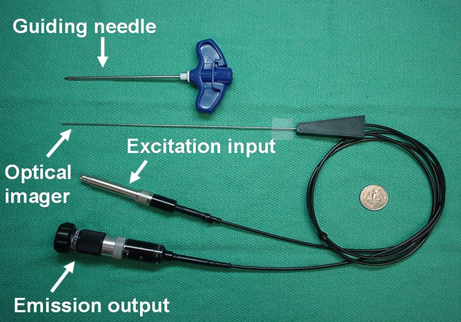
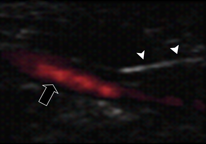
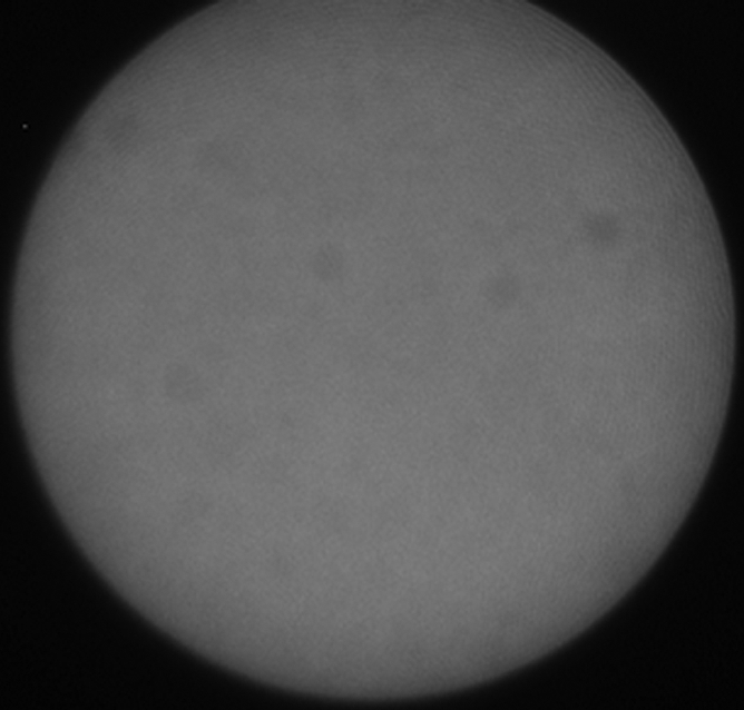
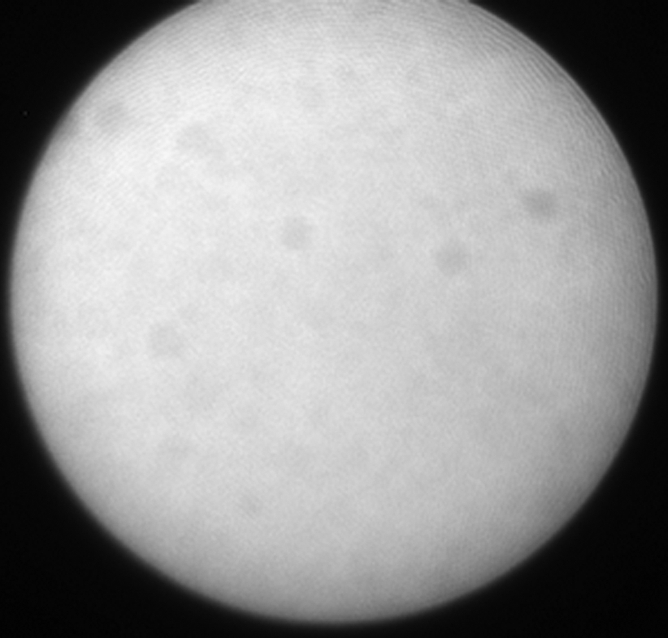
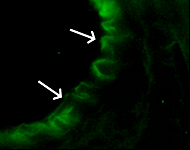
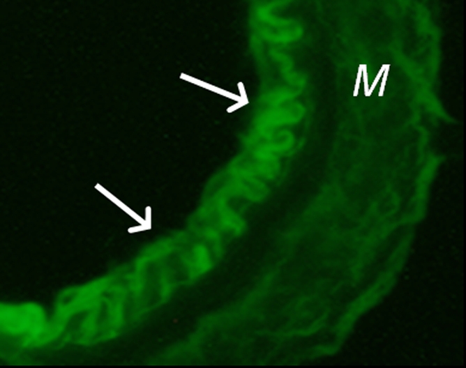
(a) A dual-port optical imager, which can be positioned percutaneously by using a guiding needle, has an input to deliver excitation light into the target and an output to detect emission light from the target. (b) With real-time ultrasonographic (US) imaging guidance, the optical imager (arrowheads) is percutaneously inserted to image a target artery (arrow) that received gene transfer for expressing green fluorescent protein. (c, d) Direct views from percutaneous optical imaging show that the emission light is brighter in (d) the green fluorescent protein–treated artery than in (c) the saline-treated control artery. (e, f) Results of fluorescent microscopy confirm higher green fluorescence from both the intima (arrows in f) and media (M) of (f) the green fluorescent protein–treated artery compared with (e) the autofluorescence from the internal elastic lamina (arrows) of the saline-treated control artery. (Reprinted, with permission, from reference 4.)
Figure 1b:
(a) A dual-port optical imager, which can be positioned percutaneously by using a guiding needle, has an input to deliver excitation light into the target and an output to detect emission light from the target. (b) With real-time ultrasonographic (US) imaging guidance, the optical imager (arrowheads) is percutaneously inserted to image a target artery (arrow) that received gene transfer for expressing green fluorescent protein. (c, d) Direct views from percutaneous optical imaging show that the emission light is brighter in (d) the green fluorescent protein–treated artery than in (c) the saline-treated control artery. (e, f) Results of fluorescent microscopy confirm higher green fluorescence from both the intima (arrows in f) and media (M) of (f) the green fluorescent protein–treated artery compared with (e) the autofluorescence from the internal elastic lamina (arrows) of the saline-treated control artery. (Reprinted, with permission, from reference 4.)
Figure 1c:
(a) A dual-port optical imager, which can be positioned percutaneously by using a guiding needle, has an input to deliver excitation light into the target and an output to detect emission light from the target. (b) With real-time ultrasonographic (US) imaging guidance, the optical imager (arrowheads) is percutaneously inserted to image a target artery (arrow) that received gene transfer for expressing green fluorescent protein. (c, d) Direct views from percutaneous optical imaging show that the emission light is brighter in (d) the green fluorescent protein–treated artery than in (c) the saline-treated control artery. (e, f) Results of fluorescent microscopy confirm higher green fluorescence from both the intima (arrows in f) and media (M) of (f) the green fluorescent protein–treated artery compared with (e) the autofluorescence from the internal elastic lamina (arrows) of the saline-treated control artery. (Reprinted, with permission, from reference 4.)
Figure 1d:
(a) A dual-port optical imager, which can be positioned percutaneously by using a guiding needle, has an input to deliver excitation light into the target and an output to detect emission light from the target. (b) With real-time ultrasonographic (US) imaging guidance, the optical imager (arrowheads) is percutaneously inserted to image a target artery (arrow) that received gene transfer for expressing green fluorescent protein. (c, d) Direct views from percutaneous optical imaging show that the emission light is brighter in (d) the green fluorescent protein–treated artery than in (c) the saline-treated control artery. (e, f) Results of fluorescent microscopy confirm higher green fluorescence from both the intima (arrows in f) and media (M) of (f) the green fluorescent protein–treated artery compared with (e) the autofluorescence from the internal elastic lamina (arrows) of the saline-treated control artery. (Reprinted, with permission, from reference 4.)
Figure 1e:
(a) A dual-port optical imager, which can be positioned percutaneously by using a guiding needle, has an input to deliver excitation light into the target and an output to detect emission light from the target. (b) With real-time ultrasonographic (US) imaging guidance, the optical imager (arrowheads) is percutaneously inserted to image a target artery (arrow) that received gene transfer for expressing green fluorescent protein. (c, d) Direct views from percutaneous optical imaging show that the emission light is brighter in (d) the green fluorescent protein–treated artery than in (c) the saline-treated control artery. (e, f) Results of fluorescent microscopy confirm higher green fluorescence from both the intima (arrows in f) and media (M) of (f) the green fluorescent protein–treated artery compared with (e) the autofluorescence from the internal elastic lamina (arrows) of the saline-treated control artery. (Reprinted, with permission, from reference 4.)
Figure 1f:
(a) A dual-port optical imager, which can be positioned percutaneously by using a guiding needle, has an input to deliver excitation light into the target and an output to detect emission light from the target. (b) With real-time ultrasonographic (US) imaging guidance, the optical imager (arrowheads) is percutaneously inserted to image a target artery (arrow) that received gene transfer for expressing green fluorescent protein. (c, d) Direct views from percutaneous optical imaging show that the emission light is brighter in (d) the green fluorescent protein–treated artery than in (c) the saline-treated control artery. (e, f) Results of fluorescent microscopy confirm higher green fluorescence from both the intima (arrows in f) and media (M) of (f) the green fluorescent protein–treated artery compared with (e) the autofluorescence from the internal elastic lamina (arrows) of the saline-treated control artery. (Reprinted, with permission, from reference 4.)
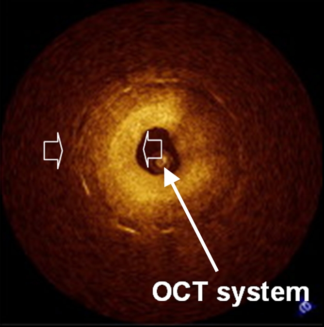
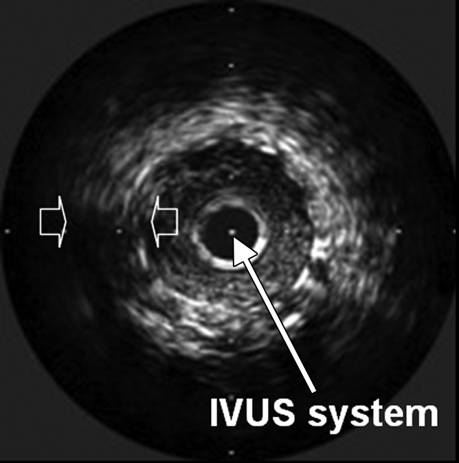
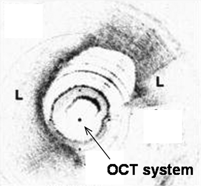
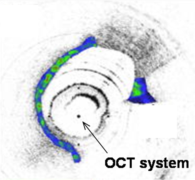
Interventional molecular imaging can provide other distinct benefits. It can generate high-spatial-resolution images of small targets in large animals and human bodies. A typical example can be taken from optical coherence tomography (OCT). OCT is an emerging biomedical optical imaging technique that enables high-spatial-resolution, cross-sectional tomographic imaging of microstructures in biologic systems (6). When modified for use with a catheter-based system, OCT becomes an endovascular optical imaging tool that provides the capability to visualize and characterize details of small vascular structures, such as the luminal border of a vessel wall and the fibrous cap of atherosclerotic plaques. Once such a close structural view is achieved, one can then detect abnormal biologic activities (such as microphage infiltration) with a high level of certainty for such tiny and deep-seated targets (Fig 2) (7,8).
Figure 2a:
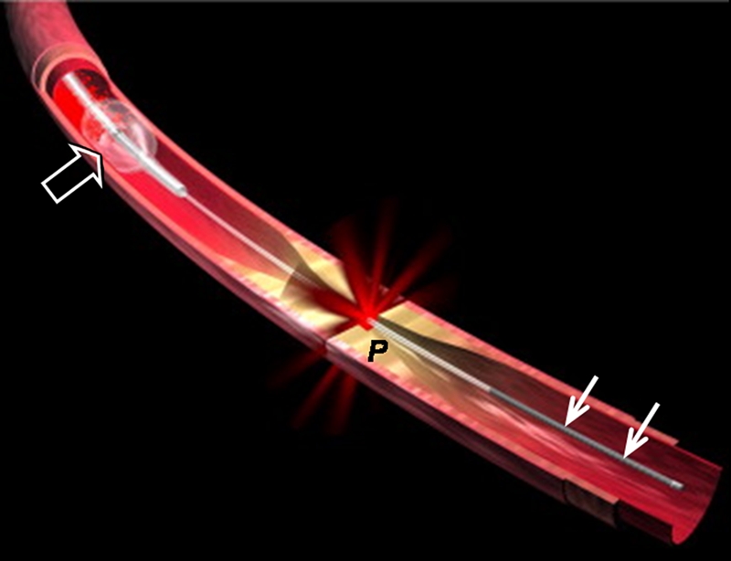
(a) Schematic of motorized pullback OCT image wire system. This system consists of a 0.016-inch image wire (solid arrows) with a balloon occlusion (open arrow). P = plaques. (b) Cross-sectional OCT image of a vessel. (c) Cross-sectional intravascular US (IVUS) image of a vessel. The luminal border (open arrows) is unclear because of wedging of the intravascular US imaging catheter. In contrast, the luminal border (open arrows in b) is clearly visualized on b. (d) Cross-sectional OCT image of an atheroma in the coronary artery obtained in vivo in a patient with acute myocardial infarction. L = lipid pool. (e) Once the OCT image of the atheroma is obtained, macrophage infiltration and density data from the fibrous cap can be displayed with pseudocolor. (Modified and reprinted, with permission, from references 7 and 8.)
Figure 2b:
(a) Schematic of motorized pullback OCT image wire system. This system consists of a 0.016-inch image wire (solid arrows) with a balloon occlusion (open arrow). P = plaques. (b) Cross-sectional OCT image of a vessel. (c) Cross-sectional intravascular US (IVUS) image of a vessel. The luminal border (open arrows) is unclear because of wedging of the intravascular US imaging catheter. In contrast, the luminal border (open arrows in b) is clearly visualized on b. (d) Cross-sectional OCT image of an atheroma in the coronary artery obtained in vivo in a patient with acute myocardial infarction. L = lipid pool. (e) Once the OCT image of the atheroma is obtained, macrophage infiltration and density data from the fibrous cap can be displayed with pseudocolor. (Modified and reprinted, with permission, from references 7 and 8.)
Figure 2c:
(a) Schematic of motorized pullback OCT image wire system. This system consists of a 0.016-inch image wire (solid arrows) with a balloon occlusion (open arrow). P = plaques. (b) Cross-sectional OCT image of a vessel. (c) Cross-sectional intravascular US (IVUS) image of a vessel. The luminal border (open arrows) is unclear because of wedging of the intravascular US imaging catheter. In contrast, the luminal border (open arrows in b) is clearly visualized on b. (d) Cross-sectional OCT image of an atheroma in the coronary artery obtained in vivo in a patient with acute myocardial infarction. L = lipid pool. (e) Once the OCT image of the atheroma is obtained, macrophage infiltration and density data from the fibrous cap can be displayed with pseudocolor. (Modified and reprinted, with permission, from references 7 and 8.)
Figure 2d:
(a) Schematic of motorized pullback OCT image wire system. This system consists of a 0.016-inch image wire (solid arrows) with a balloon occlusion (open arrow). P = plaques. (b) Cross-sectional OCT image of a vessel. (c) Cross-sectional intravascular US (IVUS) image of a vessel. The luminal border (open arrows) is unclear because of wedging of the intravascular US imaging catheter. In contrast, the luminal border (open arrows in b) is clearly visualized on b. (d) Cross-sectional OCT image of an atheroma in the coronary artery obtained in vivo in a patient with acute myocardial infarction. L = lipid pool. (e) Once the OCT image of the atheroma is obtained, macrophage infiltration and density data from the fibrous cap can be displayed with pseudocolor. (Modified and reprinted, with permission, from references 7 and 8.)
Figure 2e:
(a) Schematic of motorized pullback OCT image wire system. This system consists of a 0.016-inch image wire (solid arrows) with a balloon occlusion (open arrow). P = plaques. (b) Cross-sectional OCT image of a vessel. (c) Cross-sectional intravascular US (IVUS) image of a vessel. The luminal border (open arrows) is unclear because of wedging of the intravascular US imaging catheter. In contrast, the luminal border (open arrows in b) is clearly visualized on b. (d) Cross-sectional OCT image of an atheroma in the coronary artery obtained in vivo in a patient with acute myocardial infarction. L = lipid pool. (e) Once the OCT image of the atheroma is obtained, macrophage infiltration and density data from the fibrous cap can be displayed with pseudocolor. (Modified and reprinted, with permission, from references 7 and 8.)
Interventional molecular imaging can also be used to monitor the delivery of nontargeted imaging tracers or therapeutic agents to their specific targets. An example is the use of intravascular high-spatial-resolution MR imaging to monitor gene delivery to vascular walls (9). To be visible at MR imaging, gene vectors are mixed with an MR contrast agent and the mixture is locally infused into the target vessel wall through a balloon catheter. The distribution of the gene–contrast material mixture within the vessel wall is precisely monitored with intravascular high-spatial-resolution MR imaging. Similar molecular imaging–guided endovascular gene delivery can also be achieved by using real-time US (10), where the distribution of gene-carrying echogenic microspheres in the walls of the target vessels is dynamically visualized.
Furthermore, interventional molecular imaging can be used to enhance the effectiveness of targeted diagnosis and treatment. Currently, one of the potential clinical applications of molecular imaging is to monitor the systemic delivery of target-specific imaging and therapeutic probes (11). These modified probes can access and link to their specific molecular targets in deep-seated tissues and organs. One example technique is the modification of the diagnostic or therapeutic probes with a monoclonal antibody, J591, which specifically targets the extracellular domain of the prostate-specific membrane antigen for positron emission tomography/computed tomography (12). However, when administered systemically, these modified probes can be easily “cleared” by the kidneys and “trapped” in the liver before they are able to link with their specific targets. This physiologic clearing or trapping phenomenon can markedly decrease the effectiveness of these targeted probes. Again, this problem can be solved by applying interventional radiology to molecular imaging. With interventional radiologic techniques, these targeted probes can be delivered by means of superselectively positioned guiding catheters or needles close to such targets as tumor masses. Adoption of this approach in molecular imaging will bypass the clearing mechanism and enable superselective delivery of these imaging and therapeutic probes directly to their targets with high efficiency.
A new era of modern medical imaging will begin when molecular imaging is fully incorporated into clinical practice. To that end, interventional molecular imaging can serve as one of the important approaches for bringing molecular imaging from benches and small-animal laboratories to large-animal suites, and, ultimately, to certain clinical applications in humans.
Received July 13, 2009; revision requested August 14; revision received August 17; accepted September 30; final version accepted October 5.
Funding: This research was supported by the National Institutes of Health (grant R01 HL66187).
Author stated no financial relationship to disclose.
Abbreviation:
- OCT
- optical coherence tomography
References
- 1.Weissleder R, Mahmood U. Molecular imaging. Radiology 2001;219(2):316–333 [DOI] [PubMed] [Google Scholar]
- 2.Massoud TF, Gambhir SS. Molecular imaging in living subjects: seeing fundamental biological processes in a new light. Genes Dev 2003;17(5):545–580 [DOI] [PubMed] [Google Scholar]
- 3.Kaufman J, Lee M. Vascular and interventional radiology Philadelphia, Pa: Mosby, 2004; xi [Google Scholar]
- 4.Kar S, Kumar A, Gao F, Qiu B, Zhan X, Yang X. Percutaneous optical imaging system to track reporter gene expression from vasculatures in vivo. J Biomed Opt 2006;11(3):34008. [DOI] [PMC free article] [PubMed] [Google Scholar]
- 5.Funovics MA, Weissleder R, Mahmood U. Catheter-based in vivo imaging of enzyme activity and gene expression: feasibility study in mice. Radiology 2004;231(3):659–666 [DOI] [PubMed] [Google Scholar]
- 6.Fujimoto JG. Optical coherence tomography for ultrahigh resolution in vivo imaging. Nat Biotechnol 2003;21(11):1361–1367 [DOI] [PubMed] [Google Scholar]
- 7.Yamaguchi T, Terashima M, Akasaka T, et al. Safety and feasibility of an intravascular optical coherence tomography image wire system in the clinical setting. Am J Cardiol 2008;101(5):562?–567 [DOI] [PubMed] [Google Scholar]
- 8.Tearney GJ, Jang IK, Bouma BE. Optical coherence tomography for imaging the vulnerable plaque. J Biomed Opt 2006;11(2):021002. [DOI] [PMC free article] [PubMed] [Google Scholar]
- 9.Yang X, Atalar E, Li D, et al. Magnetic resonance imaging permits in vivo monitoring of catheter-based vascular gene delivery. Circulation 2001;104(14):1588–1590 [DOI] [PubMed] [Google Scholar]
- 10.Du X, Yang Y, Le Visage C, et al. In vivo US monitoring of catheter-based vascular delivery of gene microspheres in pigs: feasibility. Radiology 2003;228(2):555–559 [DOI] [PubMed] [Google Scholar]
- 11.Weissleder R. Molecular imaging in cancer. Science 2006;312(5777):1168–1171 [DOI] [PubMed] [Google Scholar]
- 12.Bouchelouche K, Capala J, Oehr P. Positron emission tomography/computed tomography and radioimmunotherapy of prostate cancer. Curr Opin Oncol 2009;21(5):469–474 [DOI] [PMC free article] [PubMed] [Google Scholar]