

Abstract
Just as the Wright brothers implemented controls to achieve stable airplane flight, flying insects have evolved behavioral strategies that ensure recovery from flight disturbances. Pioneering studies performed on tethered and dissected insects demonstrate that the sensory, neurological, and musculoskeletal systems play important roles in flight control. Such studies, however, cannot produce an integrative model of insect flight stability because they do not incorporate the interaction of these systems with free-flight aerodynamics. We directly investigate control and stability through the application of torque impulses to freely flying fruit flies (Drosophila melanogaster) and measurement of their behavioral response. High-speed video and a new motion tracking method capture the aerial “stumble,” and we discover that flies respond to gentle disturbances by accurately returning to their original orientation. These insects take advantage of a stabilizing aerodynamic influence and active torque generation to recover their heading to within 2° in < 60 ms. To explain this recovery behavior, we form a feedback control model that includes the fly’s ability to sense body rotations, process this information, and actuate the wing motions that generate corrective aerodynamic torque. Thus, like early man-made aircraft and modern fighter jets, the fruit fly employs an automatic stabilization scheme that reacts to short time-scale disturbances.
Keywords: flight control, insect flight, stability, perturbation, fruit fly
Locomotion through natural environments demands mechanisms that maintain stability in the face of unpredictable disturbances. Behavioral strategies play a particularly important role in controlling the flight of insects (1–7), because even gentle air currents can cause large disruptions to the intended flight path. Insects must also contend with the intrinsic instability of flapping flight (8, 9) and the large fluctuations in aerodynamic forces caused by slight variations in wing motions (10, 11). Corrective behavior often takes advantage of vision (1, 2). For fruit flies, however, reaction time to visual stimuli is at least 10 wingbeats (12), so these insects must employ faster sensory circuits to recover from short time-scale disturbances and instabilities. To probe this fast control strategy, we devised an experimental method that imposes impulsive mechanical disturbances (6, 13) to flying insects while allowing us to measure relevant aspects of flight behavior. We first glue tiny ferromagnetic pins to fruit flies and image their free flight using three orthogonally oriented high-speed video cameras (Methods and SI Text). When a fly enters the filming volume, an optical trigger detects the insect, initiates recording, and activates a pair of Helmholtz coils that produce a magnetic field. The field and pin are both oriented horizontally, so the resulting torque on the pin reorients the yaw, or heading angle, of the insect (Fig. 1). We then use a new motion tracking technique to extract the three-dimensional body and wing motions (14). The videos and extracted flight data reveal that these insects respond to such mechanical perturbations by attempting to correct their course, and this reaction depends on the strength of the disturbance.
Fig. 1.

Three-dimensional reconstruction of a recovery maneuver. Three orthogonal high-speed cameras capture 35 frames per wingbeat, and the still images shown on the side panels are spaced by about four wingbeats. The corresponding three-dimensional wing and body configurations extracted from the images are displayed on a computer-generated model of the fruit fly (body length 2.5 mm). As the fly descends from left to right, we apply a magnetic field (Red Looped Arrow) for one wingbeat that torques the ferromagnetic pin (Bronze Rod) glued to its back and reorients the insect’s flight heading. The insect responds to the flight perturbation by making a corrective turn that lasts several wingbeats.
By conducting experiments at various values of the applied torque, we induce different maximal deflections in the yaw angle, Δψmax. As diagrammed in the inset of Fig. 2, we characterize the response by measuring the error, Δψerr, which is the difference between the final and initial yaw angles. In all 23 trials, the insects exhibit corrective responses such that Δψerr < Δψmax, as shown in Fig. 2. Impressively, for gentle disturbances, the insects correct their heading nearly perfectly, with a mean Δψerr of 2° (15 trials with Δψmax < 45°). For stronger perturbations, however, the corrective responses are not sufficient to return the flies to their original heading. For cases of both inaccurate and accurate correction, the insects exhibit a stereotypical response in which specific changes in the motions of the wings drive the reorientation of the body.
Fig. 2.

Accuracy of the corrective response. (Inset) For each trial, the error Δψerr (final minus initial yaw) and maximum induced deflection Δψmax are measured from the yaw dynamics. In the main figure, the error is plotted against the deflection for 23 experiments. The dashed blue horizontal line is the predicted perfect correction from a linear control model, and the solid blue line is the result of a nonlinear model. See text for details of both models.
The yaw dynamics, ψ(t), for a case in which the fly accurately corrects its heading is visualized in Fig. 3A and plotted in Fig. 3B. At time t = 0, the field is turned on for 5 ms (Vertical Pink Stripe), or about one wingbeat period, T = 4.5 ms. In about three wingbeats, the fly experiences its maximal deflection of Δψmax = 19°, and by the recovery time Δtrec = 10 T or 45 ms, it has recovered its orientation to within 2° of the original yaw. To reorient its body, the fly induces differences between the right and left wing motions, thus generating aerodynamic torque. A recent analysis of free-flight turning maneuvers of fruit flies indicates that these insects generate yaw torque by asymmetrically adjusting the wing angles of attack, α, defined as the inclination angle of each wing relative to its velocity (15). Qualitatively, these differences can be seen in the top-view stills from the flight videos, as shown in Fig. 3A. The insect beats its wings back and forth, and these images capture the wings as they move forward. In the third image, the right and left wings have different projected areas due to different attack angles. When the attack angle on one wing is greater than the other, the larger area presented to the flow induces a greater drag force, and this unbalanced drag causes the insect to rotate (15). We quantify the asymmetric “rowing” wing motions by measuring the complete wing kinematics (14), and we verify that fruit flies drive yaw corrective maneuvers by differentially varying wing angle of attack. Specifically, in Fig. 3C, we plot the difference between the right and left wing attack angles averaged over each wingbeat, Δα (Black Data). Prior to the perturbation and for the first three wingbeats after the disturbance, Δα = 0, indicating that the wings beat symmetrically. After this initial delay, asymmetries in the wing motions appear for about five wingbeats, indicating the insect is actively generating corrective torque. The accuracy of the recovery indicates that a refined control strategy underlies the response of fruit flies to in-flight perturbations.
Fig. 3.

Body and wing motions for a case of accurate correction. (A) Top-view images of the insect before the perturbation, during the induced rightward rotation, during the corrective turn leftward, and after accurate recovery. The yaw angle, or heading, is shown as a red arrow, and the wings are moving forward in each image. The differences in right and left wing area in the third image indicate differences in angles of attack that drive the corrective turn. (B) Yaw angle as a function of time measured in wingbeat periods, T = 4.5 ms. The red stripe indicates the 5 ms during which the perturbing torque, Next = 0.8 × 10⁻⁹ Nm, is applied. The yaw is experimentally measured (Open Circles), and a control model (Blue Curve) is fit to the experimental data. The parameters used for the fit are: I = 0.6 × 10⁻¹³ kg m2, β = 1.0 × 10⁻¹¹ kg m2 s-1, Δt = 2.5 T, KP = 5.0 × 10⁻¹⁰ kg m2 s-2, KD = 4.1 × 10⁻¹² kg m2 s-1. See text for description of the model (Eqs. 1–4). (C) The attack angle difference between wings averaged over each wingbeat, Δα, is plotted in black (mean and standard error of the mean). These data are compared to the torque predicted by the model (Blue Curve).
To reveal this strategy, we construct a physics-based model of the observed behavioral response. Combining all relevant yaw torques, the body rotational dynamics are described by
| [1] |
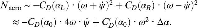
where I is the yaw moment of inertia of the insect body, Naero is the aerodynamic torque on the insect, and Next is the applied torque due to the magnetic field. For wings that beat in a horizontal stroke plane, only the aerodynamic drag on the wings contributes to yaw torque. In general, the drag on each wing is proportional to the wing’s drag coefficient, CD(α), times the square of its speed relative to air. We consider the general case in which the right and left wing angles of attack may be different, and each wing beats with mean angular speed ω relative to the body. For an insect body rotating at angular velocity  , the stroke-averaged net aerodynamic torque is found by summing each wing’s contribution (SI Text):
 |
[2] |
Here, we have kept leading order terms in  and taken advantage of the linearity of the coefficient dependence on attack angle:
  , where α0 = 45° and
  is the slope at α0. This aerodynamic torque has two components. The first is a damping torque, and it is proportional to the yaw velocity
  with a damping coefficient β that depends on aerodynamic properties of the wings. The second is the torque due to the asymmetric wing motions, Nfly = γ·Δα, and it is proportional to Δα with a second aerodynamic constant γ. Combining Eqs. 1 and 2, we arrive at the yaw dynamical equation
| [3] |
Thus, the active torque exerted by the fly must act in concert with aerodynamic damping and inertia to restore body orientation.
To physically interpret these results, first consider the scenario just after the perturbation is applied. Here, the wings beat symmetrically, Δα = 0, so that Nfly = 0. The induced body rotation, however, introduces a difference in the wing velocities and hence a difference in the drag forces acting on the wings (16–18), as illustrated in Fig. 4A and B. Then Eq. 3 reduces to 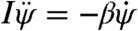 . Thus, an induced yaw rotation exponentially decays with a characteristic damping time of about two wingbeat periods, I/β ≈ 2T (SI Text). This time scale is consistent with the decay of yaw velocity during the few wingbeats after the applied perturbation (Fig. 3B). As the insect recovers, its wings beat asymmetrically, as shown in Fig. 4C and D, and torque is generated from unbalanced drag on the wings. For example, to turn rightward, the fly employs a higher average attack angle α on the right wing for the forward stroke and a higher α on the left wing for the backward stroke (15). These rowing motions generate differential drag on the wings and thus produce the yaw torque, Nfly, that drives the corrective body rotation.
Fig. 4.

Physical and biological elements of the flight control model. (A) and (B) Aerodynamics of symmetric flapping flight during body rotation. Top-view images of the fly as it is rotated to its right by the perturbing torque show that the insect continues to beat symmetrically. The imposed rotation induces differences in wing velocity that generate unbalanced drag on the wings. (C) and (D) Active steering is driven by differences in wing angles of attack. To turn rightward, the insect assumes different pitch angles for the right and left wings that generate an unbalanced drag-based torque. (E) The haltere organs (S) sense body rotations, the neural controller (C) processes this information, and the flight motor (M) drives the wing motions that generate corrective aerodynamic torque (A). (F) Information flow diagram for the insect flight control model. The upper circuit describes the feedback loop used for correction, and the lower circuit shows the detailed control model. After an initial time delay, a term that is proportional to the sensed yaw-rate signal and a term that integrates this signal are added to determine the output torque exerted by the fly.
The ability to adjust their response for perturbations of different strengths (Fig. 2) suggests that these insects sense their body motion and use this information to determine the corrective response. In fact, flies are equipped with a pair of small vibrating organs called halteres that act as gyroscopic sensors (3). Anatomical, mechanical, and behavioral evidence indicates that the halteres serve as detectors of body angular velocity that quickly trigger muscle action (3, 7, 19). These findings suggest that these insects drive their corrective response using an autostabilizing feedback loop in which the sensed angular velocity serves as the input to the flight controller. As diagrammed in Fig. 4E, the velocity is sensed by the halteres (S), processed by a neural controller (C), and transmitted by the flight motor (M) into specific wing motions that generate aerodynamic torque (A). In the upper control diagram of Fig. 4F, the loop is triggered when an external torque, Next, induces a yaw velocity,  , that is determined by the physics (P) of a damped, inertial body. The active torque exerted by the insect, Nfly, feeds back to determine the yaw dynamics (Eq. 3) and thus closes the loop.
A minimal linear control model (20) that guarantees perfect correction (Fig. 2, Dashed Blue Horizontal Line) in response to short-lived disturbances requires that the exerted torque contain a term proportional to the integral over time of the sensed angular velocity (SI Text). However, we find that a pure integrator fails to account for the fast recovery time observed in the flight data. By adding a term that is proportional to the angular velocity itself, we arrive at a good match to the yaw data, as shown by the model fit shown in Fig. 3B (Blue Curve). This model is a proportional–derivative (PD) scheme (20) that controls yaw angle using a yaw-rate sensor, and the corrective torque can be written as:
| [4] |
Here, KP and KD are gain constants and Δt is the response delay time that we measure to be 2–5 wingbeat periods. This loop delay may reflect both neural latency and inertia of the sensors and motor (19, 21). A diagram of this control scheme is shown in the lower section of Fig. 4F. In Fig. 3C, we overlay the torque, Nfly, predicted by Eq. 4 on the measured Δα data and find a strong agreement between the model and experiment. Furthermore, both curves remain positive throughout the corrective maneuver, which reflects a simple strategy for linearly damped systems: to recover, the fly need only counter the perturbing impulse with an impulse of equal strength but opposite direction. To prove this, we integrate Eq. 3 over time to arrive at
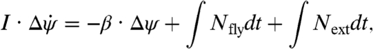 |
[5] |
where the symbol Δ indicates the net change in each quantity. Because the system is damped and all torques act over finite periods of time, the change in yaw velocity  . Perfect recovery implies Δψ = 0, which requires that ∫Nflydt = -∫Nextdt. Thus, accurate recovery simply requires a counterimpulse of equal magnitude to the perturbing impulse. These insects employ this strategy and do not brake the perturbing rotation nor their self-induced corrective rotation but instead take advantage of aerodynamic damping to come to each stop.
The interplay of active and passive torques also sets the overall time scale for recovery. Using the flight control model with average system parameters Δt, T, I, β, KP, and KD, the control model predicts that the total recovery time, Δtrec, rises sharply and then plateaus for increasing imposed deflections, as shown by the dashed blue curve in Fig. 5. The experimentally measured recovery times confirm this trend, and this agreement indicates that the model is robust, with system parameters varying by ± 15% among individuals.
Fig. 5.

Recovery time, Δtrec, increases for stronger perturbations. Here, Δtrec is plotted for cases of accurate correction, and the model prediction is the dashed blue curve. The theoretical curve marks the total time to return to within 2° of the original yaw angle and is generated using the mean parameter values extracted from fits to trials of accurate recovery: I = 0.9 × 10⁻¹³ kg ·m2, β = 0.9 × 10⁻¹¹ kg ·m2·s-1, Δt = 3.5 T, T = 0.0045 s, KP = 5.9 × 10⁻¹⁰ kg ·m2 ·s-2, KD = 5.3 × 10⁻¹² kg ·m2 ·s-1.
Finally, the increasing error for stronger disturbances (Fig. 3) may reflect sensor saturation. Specifically, we form a model that modifies the controller of Eq. 4 such that the sensors can only register velocities up to a maximum of  , a hypothesis consistent with the strong nonlinear mechanical response of vibratory gyroscopes (22). This nonlinear model gives the solid blue error curve in Fig. 2 that accounts for both the accurate and inaccurate responses. The agreement between the model prediction and the experimental data indicates that this simple model based on sensor saturation is sufficient to explain why fruit flies are unable to accurately recover from strong perturbations.
These models reveal the physical and biological aspects of yaw autostabilization in fruit flies. Future experiments that modify the orientations of the magnetic coils and pin will investigate the control of pitch and roll. Studies that combine such perturbations will elucidate how these insects coordinate their response to complex disturbances. Aerodynamically, these experiments on freely flying insects demonstrate the critical importance of considering the coupled wing and body motions for studies of flight behavior. In particular, this coupling gives rise to a strong damping of yaw rotation (17, 18), and our results show that autostabilizing fruit flies use this damping rather than active braking to stop body rotation. This important effect is, of course, entirely removed in studies that rigidly tether insects (12). Even in experimental preparations that loosely confine the motion of insects (23, 24), turning kinematics are different from those observed in free-flight studies (10, 15, 25). These discrepancies indicate that restrictive preparations interfere with flight behavior, and the results of such studies must be interpreted in light of this influence.
Biologically, our findings lead to several hypotheses regarding the roles of the systems that underlie flight control in the fruit fly. First, our results suggest that the halteres are unable to detect high rotation rates of the body, and recordings from sensory neurons should reflect this limitation (26). Second, we predict that the neural circuitry between the halteres and wing muscles (21) transmits a position- and rate-driven signal. Determination of the wiring and firing of these neurons would offer insight into the neurological basis of signal integration and summation (27). Third, we find that wing orientation adjustments during autostabilization are remarkably similar to those used for voluntary turns (15) and hypothesize that they result from the same musculoskeletal elements (21). We stress, however, that our experiments strictly address the fruit fly’s reflexive turning response to mechanical stimuli rather than visually induced turning behavior. The interaction between the haltere control loop and visual system loops in structuring such voluntary turns remains an open problem (21). Nevertheless, we expect that the aerodynamic and behavioral models presented here will be key components of general flight navigation models for the fruit fly.
Flight control principles uncovered in this model organism may also apply more broadly, and this work provides a template for future studies aimed at determining if other animals employ flight autostabilization. The control strategies across different animals are likely to share common features, because the physics of body rotation is similar across many animals during flapping-wing flight (18). Additionally, animals that lack halteres may use functionally equivalent mechanosensory structures such as antennae (28). Finally, the control architecture of the fruit fly offers a blueprint for stabilization of highly maneuverable flapping-wing flying machines (29).
For fixed-wing machines, the need to overcome instabilities spurred the invention of autostabilizing systems by 1912, only 9 years after the Wright brothers first manually controlled airplane flight (30, 31). The development of such automatic steering systems also led to the first formal description of proportional–integral–derivative control schemes (32) and advanced gyroscopic sensor technology (30). The fruit fly’s autostabilization response is well-modeled by a simple PD scheme that receives input from gyroscopic halteres, and, like airplanes (16, 30), uses fine adjustment of wing orientation to generate corrective torques. Roughly 350 million years after insects took flight (33), man converged to this solution for the problem of flight control and joined animals in the skies.
Methods
Refer to SI Text for details of the methods summarized below.
Videography.
Three synchronized, orthogonal high-speed cameras record at 8,000 frames per second, as described in ref. 14. Each camera is backlit by a bright red light-emitting diode. Recording is initiated by an optical detector system that triggers when an insect flies in the region of interest.
Magnetic Torque Perturbation.
The optical detector also triggers a circuit that drives a 4 amp, 5 ms direct current pulse through paired Helmholtz coils placed inside a clear flight chamber. The magnetic field strength is on the order of 10-2 tesla, or 103 times stronger than the Earth’s field.
Motion Tracking.
The three-dimensional body and wing coordinates are extracted from the flight videos using a recently developed method (14). The yaw angle is measured directly. The measured wing orientation angles are used to calculate the attack angle difference Δα, which is defined to be the right minus left attack angles for the forward stroke and left minus right angles for the backward stroke. Though the corrective turns are accompanied by changes in other aspects of the wing motions (i.e., stroke amplitude), a recent analysis implicates attack angle difference as the aerodynamically relevant parameter (15). We average this parameter over each wingbeat, because the modulation of Δα occurs over longer time scales (15). For the Δα data of Fig. 3C, the vertical bars indicate the standard error of the mean taken over the ∼35 measurements per wingbeat and thus reflect both measurement error and actual intra-wingbeat variation. The magnitude, duration, and variation of the Δα data in these experiments are similar to those measured for free-flight turns (15).
Animal Preparation.
During each day of experiments, about 40 common fruit flies (D. melanogaster) from out-bred laboratory strains are first selected for strong flight capability. A carbon steel wire 1.5 mm long and 0.006 inch in diameter is carefully glued to the notum, the dorsal surface of the insect’s thorax. The attached pin’s weight is 15–20% that of the typical fly, and we analyze only sequences in which the pin does not interfere with the motion of the wings.
Control Experiments.
Videos that capture the flight of insects whose pins had fallen off show no change in behavior upon application of the magnetic field. Also, videos captured in a darkened laboratory show no qualitative or quantitative difference in corrective behavior.
Models.
The Simulink software package for MATLAB (The Mathworks Inc.) numerically integrates the linear and nonlinear delay differential equations. For each sequence, we calculate approximate values for the morphological and aerodynamic parameters I and β. The value of the delay time Δt is determined directly from the time-course of the measured Δα data. We then select the value of Next that yields the measured maximal deflection of yaw. Finally, the best-fit match to the complete time-course of yaw determines the values of the free parameters KP and KD. All model parameters vary by ± 15% among different individuals.
Supplementary Material
Acknowledgments.
We thank A. Clark, J. Mezey, and S. Hackett for providing the insects; L. Koerner, K. Jensen, and M. Lory-Moran for assistance with the electronics; A. Ruina, R. Hoy, B. Arthur, C. Gilbert, and J. Fetcho for discussions; and the National Science Foundation for support.
Footnotes
The authors declare no conflict of interest.
This article contains supporting information online at www.pnas.org/cgi/content/full/1000615107/DCSupplemental.
References
- 1.Dudley R. The Biomechanics of Insect Flight: Form, Function, Evolution. Princeton: Princeton Univ Press; 2000. [Google Scholar]
- 2.Taylor GK, Krapp HG. Sensory systems and flight stability: What do insects measure and why? Adv Insect Physiol. 2007;34:231–316. [Google Scholar]
- 3.Pringle JWS. The gyroscopic mechanism of the halteres of Diptera. Philo Trans R Soc B. 1948;233:347–384. [Google Scholar]
- 4.Heide G. In BIONA report 2. Stuttgart: Fischer; 1983. Neural mechanisms of flight control in Diptera; pp. 35–52. [Google Scholar]
- 5.Heide G, Götz KG. Optomotor control of course and altitude in Drosophilais correlated with distinct activities of at least three pairs of steering muscles. J Exp Biol. 1996;199:1711–1726. doi: 10.1242/jeb.199.8.1711. [DOI] [PubMed] [Google Scholar]
- 6.Mittelstaedt H. Physiology of the sense of balance of flying dragonflies. J Comp Physiol A. 1950;32:422–463. (Translated from German) [Google Scholar]
- 7.Dickinson MH. Haltere-mediated equilibrium reflexes of the fruit fly, Drosophila melanogaster. Philo Trans R Soc B. 1999;354:903–916. doi: 10.1098/rstb.1999.0442. [DOI] [PMC free article] [PubMed] [Google Scholar]
- 8.Taylor GK, Thomas ALR. Dynamic flight stability in the desert locust Schistocerca gregaria. J Exp Biol. 2003;206:2803–2829. doi: 10.1242/jeb.00501. [DOI] [PubMed] [Google Scholar]
- 9.Sun M, Xiong Y. Dynamic flight stability of a hovering bumblebee. J Exp Biol. 2005;208:447–459. doi: 10.1242/jeb.01407. [DOI] [PubMed] [Google Scholar]
- 10.Fry SN, Sayaman R, Dickinson MH. The aerodynamics of free-flight maneuvers in Drosophila. Science. 2003;300:495–498. doi: 10.1126/science.1081944. [DOI] [PubMed] [Google Scholar]
- 11.Fry SN, Sayaman R, Dickinson MH. The aerodynamics of hovering flight in Drosophila. J Exp Biol. 2005;208:2303–2318. doi: 10.1242/jeb.01612. [DOI] [PubMed] [Google Scholar]
- 12.Heisenberg M, Wolf R. In Visual Motion and its Role in the Stabilization of Gaze. Amsterdam: Elsevier; 1993. The sensory-motor link in motion-dependent flight control of flies; pp. 265–283. [PubMed] [Google Scholar]
- 13.Jindrich DL, Full RJ. Dynamic stabilization of rapid hexapedal locomotion. J Exp Biol. 2002;205:2803–2823. doi: 10.1242/jeb.205.18.2803. [DOI] [PubMed] [Google Scholar]
- 14.Ristroph L, Berman GJ, Bergou AJ, Wang ZJ, Cohen I. Automated hull reconstruction motion tracking (HRMT) applied to sideways maneuvers of free-flying insects. J Exp Biol. 2009;212:1324–1335. doi: 10.1242/jeb.025502. [DOI] [PubMed] [Google Scholar]
- 15.Bergou AJ, Ristroph L, Guckenheimer J, Cohen I, Wang ZJ. Fruit flies modulate passive wing pitching to generate in-flight turns. arXiv:0910.0671v1. 2009. [DOI] [PubMed]
- 16.Stengel RF. Flight dynamics. Princeton: Princeton Univ Press; 2004. [Google Scholar]
- 17.Hesselberg T, Lehmann F-O. Turning behavior depends on frictional damping in the fruit fly Drosophila. J Exp Biol. 2007;210:4319–4334. doi: 10.1242/jeb.010389. [DOI] [PubMed] [Google Scholar]
- 18.Hedrick TL, Cheng B, Deng X. Wingbeat time and the scaling of passive rotational damping in flapping flight. Science. 2009;324:252–255. doi: 10.1126/science.1168431. [DOI] [PubMed] [Google Scholar]
- 19.Sandeman DC, Markl H. Head movements in flies (Calliphora) produced by deflexion of the halteres. J Exp Biol. 1980;85:43–60. [Google Scholar]
- 20.Bechhoefer J. Feedback for physicists: A tutorial essay on control. Rev Mod Phys. 2005;77:783–836. [Google Scholar]
- 21.Dickinson MH. The initiation and control of rapid flight maneuvers in fruit flies. Integr Comp Biol. 2005;45:274–281. doi: 10.1093/icb/45.2.274. [DOI] [PubMed] [Google Scholar]
- 22.Apostolyuk V. In MEMS/NEMS Handbook: Techniques and Applications. New York: Springer; 2006. Theory and design of micromechanical vibratory gyroscopes; pp. 173–195. [Google Scholar]
- 23.Mayer M, Vogtmann K, Bausenwein B, Wolf R, Heisenberg M. Flight control during “free yaw turns” in Drosophila melanogaster. J Comp Physiol A. 1988;163:389–399. [Google Scholar]
- 24.Bender JA, Dickinson MH. Visual stimulation of saccades in magnetically tethered Drosophila. J Exp Biol. 2006;209:3170–3182. doi: 10.1242/jeb.02369. [DOI] [PubMed] [Google Scholar]
- 25.Tammero LF, Dickinson MH. The influence of visual landscape on the free flight behavior of the fruit fly Drosophila melanogaster. J Exp Biol. 2002;205:327–343. doi: 10.1242/jeb.205.3.327. [DOI] [PubMed] [Google Scholar]
- 26.Fox JL, Daniel TL. A neural basis for gyroscopic encoding in the halteres of Holorusia. J Comp Physiol A. 2008;194:887–897. doi: 10.1007/s00359-008-0361-z. [DOI] [PubMed] [Google Scholar]
- 27.Robinson DA. Integrating with neurons. Annu Rev Neurosci. 1989;12:33–45. doi: 10.1146/annurev.ne.12.030189.000341. [DOI] [PubMed] [Google Scholar]
- 28.Sane SP, Dieudonné A, Willis MA, Daniel TL. Antennal mechanosensors mediate flight control in moths. Science. 2007;315:863–866. doi: 10.1126/science.1133598. [DOI] [PubMed] [Google Scholar]
- 29.Wood RJ. First take-off of a biologically-inspired at-scale robotic insect. IEEE T Robot. 2008;24:341–347. [Google Scholar]
- 30.Abzug MJ, Larrabee EE. Airplane Stability and Control: A History of the Technologies That Made Aviation Possible. Cambridge: Cambridge Univ Press; [Google Scholar]
- 31.Wright O, Wright W. 821,393. US Patent. 1906
- 32.Minorsky N. Directional stability of automatically steered bodies. J Am Soc Nav Eng. 1922;34:280–309. [Google Scholar]
- 33.Grimaldi D, Engel MS. Evolution of the insects. Cambridge: Cambridge Univ Press; 2005. [Google Scholar]
Associated Data
This section collects any data citations, data availability statements, or supplementary materials included in this article.