Abstract
The assembly of nanoparticles into three-dimensional (3D) architectures could allow for greater control of the interactions between these particles or with molecules. DNA tubes are known to form through either self-association of multi-helix DNA bundle structures or closing up of 2D DNA tile lattices. By the attachment of single-stranded DNA to gold nanoparticles, nanotubes of various 3D architectures can form, ranging in shape from stacked rings to single spirals, double spirals, and nested spirals. The nanoparticles are active elements that control the preference for specific tube conformations through size-dependent steric repulsion effects. For example, we can control the tube assembly to favor stacked-ring structures using 10-nanometer gold nanoparticles. Electron tomography revealed a left-handed chirality in the spiral tubes, double-wall tube features, and conformational transitions between tubes.
Nanoparticles can exhibit distinctive electronic, magnetic, and photonic properties (1), and their assembly into well-defined one-dimensional (1D), 2D, and 3D architectures with geometric controls could add to their functionality. DNA-mediated assembly of nanoparticles is an attractive way to organize both metallic and semiconducting nanoparticles into periodic or discrete 1D and 2D structures (1–14) through the programmable base-pairing interactions and the ability to construct branched DNA nanostructures of various geometries. Recent success in using DNA as a molecular glue to direct gold nanoparticles (AuNPs) into periodic 3D crystalline lattices further demonstrates the power of DNA as building blocks for 3D nanoengineering (15, 16).
Here, we report a group of complex 3D geometric architectures of AuNPs created using DNA tile-mediated self-assembly. These are tubular nanostructures with various conformations and chiralities resembling those of carbon nanotubes. The nanoparticle tube assembly can be engineered both by the underlying DNA tile scaffolds and the nanoparticles themselves. Previous work in structural DNA nanotechnology has shown that DNA tubes can form through either the self-association of multi-helix DNA bundle structures or the closing up of 2D DNA tile lattices (17–26). The forces that drive tube formation have been attributed to the intrinsic curvature of the tile-array (21) and the thermodynamic requirement to lower the free energy of the system by minimizing the number of unpaired sticky ends (22). The intrinsic dimensional anisotropicity of the DNA tiles also plays an important role in the kinetic control of the tube growth (26).
In all of the above studies, the true 3D conformations of DNA tubes have never been revealed in detail because of limitations in microscopic imaging techniques; deposition of the samples on a surface for atomic force microscope (AFM) or transmission electron microscope (TEM) imaging usually causes flattening and sometimes opening of the tubes. This limitation has prevented a comprehensive understanding of the structural features of DNA nanotubes. For example, the handedness of the chiral tubes can be better revealed with 3D structural characterization of the samples. Furthermore, there has been no report to explore the use of DNA tiles to control the assembly of AuNPs into tubular architectures, which may lead to interesting properties for nanoelectronics and photonics applications.
We considered the incorporation of AuNPs into a planar DNA tile array by conjugating each AuNP with a single DNA strand. We propose that AuNPs lined up on the DNA array will have systematic steric and electrostatic repulsion effects that will favor DNA tube formation. In addition, we rationalize that varying the size of the AuNPs in such constructs could help control the tube conformation. The use of metallic NPs provides an effective image-enhancement method to probe the 3D DNA nanostructures with electron microscopy because of their high electrical contrast.
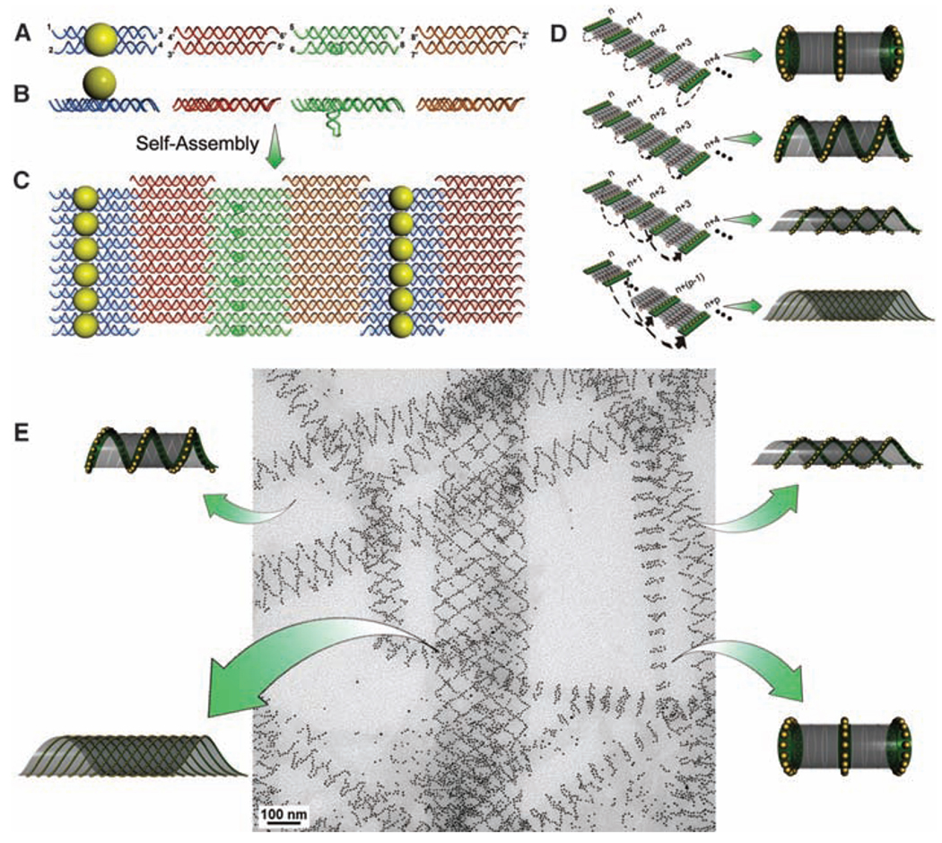
An array system formed from four double-crossover (DX) DNA tiles (27) was used in the current study (Fig. 1, A and B). In the first design, we modified two out of the four component tiles (28). The central strand in the A tile was conjugated with a thiol group, which was then linked to a 5-nm AuNP in a 1:1 ratio (28) so that, when self-assembled, each A tile carried a AuNP on one side of the tile (shown as the top side). The C tile was modified with a DNA stem loop extending out of the tile surface toward the bottom side (Fig. 1, A and B). As illustrated in Fig. 1C, these four tiles were designed to self-assemble into a 2D array through sticky-end associations, with the A tiles forming parallel lines of AuNPs that are all located at the top side of the array and the C tiles forming parallel lines of stem loops at the bottom side of the array. The designed periodicity between the neighboring A tiles is expected to be ~64 nm when the tiles are closely packed side by side. Additionally, the intrinsic curvature of the array is expected to be cancelled because the A and C tiles face one direction whereas the B and D tiles face the opposite direction (20–22, 26). However, in the presence of the 5-nm AuNPs, which have diameters that are comparable or even greater than the center-to-center distances of the neighboring A tiles within the parallel stripes (4 to 5 nm), the strong electrostatic and steric repulsions between the neighboring AuNPs force the 2D arrays to curl up to avoid direct contact between the particles. This curling will lead to tube formation with the particles displayed on the outer surface of the tubes.
Fig. 1.
The design of a DNA tile system for the formation of a variety of tubular structures carrying 5-nm AuNPs. (A and B) Top and side view of the four DX tiles (A tile, blue; B tile, red; C tile, green; and D tile, brown). The A tile carries a 5-nm AuNP on the top of the tile. The C tile carries a DNA stem loop pointing downward. (C) The four different tiles are designed to self-assemble into a 2D array displaying parallel lines of AuNPs. (D) Possible ways for the corresponding edge tiles on opposite sides of the 2D array to associate and lead to formation of tubes displaying patterns of AuNPs in stacked rings, single spirals, double spirals, and nested spiral tubes. (E) The different tube conformations were observed in a single TEM image.
The stem loops on the C tiles in this design were placed on surfaces opposite from the AuNPs as a counterforce to resist tube formation (that is, to increase the energy barrier for bending the 2D array). However, because the AuNPs are much larger than the DNA stem loops, their forces are not perfectly counterbalanced. The tile arrays still have a tendency to curl up into tubes with the stem loops wrapped inside and the AuNPs displayed on the outside.
There are a few different possible ways for the edge tiles to associate in the tube formation (Fig. 1D). When the edge tiles at one side of the array that associate with the corresponding edge tiles at the opposite side of the array are within the same lines, a tube displaying stacked rings of AuNPs will form. When the corresponding edge tiles that associate are at neighboring lines (with 1 line offset), tubes displaying a single spiral of nanoparticles will result. Depending on the sign of the offset (n→n + 1 lines, or n→n − 1 lines), the spiral can potentially display either a left-hand or right-hand chirality. Similarly, when the corresponding edge tiles that associate are at alternating lines (n → n + 2 lines, or n → n − 2 lines), tubes displaying double spirals of nanoparticles will result. When the corresponding edge tiles are at lines with a larger interval (Δn ≥ 3 lines), spiral tubes will be nested.
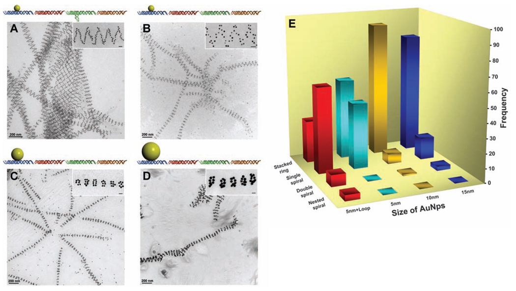
Varieties of tubes with different conformations were observed from the above design (Fig. 1E and Fig. 2A and fig. S2) (28). The results of statistical image analysis are shown in Fig. 2E (red bars). The enthalpy changes of the formation of the spiral tubes and the stacked-ring tubes are similar because the same number of base pairings is satisfied per unit of tile. The free energy changes differ by the bending energy because the tubes have different diameters and hence curvatures, and an extra twisting energy for the spiral tube to form. The transition between the two forms of tubes requires a large activation-energy barrier (simultaneously breaking many sticky-end pairs and reforming all of the sticky-end pairs at distance a few tiles away). Thus, the distribution of tube-product conformations can be considered the result of the differences in the bending energy and twisting energy. From the broad distribution of the different tube conformations in this sample (a significant percentage of the resultant tubes are single and multiple spiral tubes), we can deduce that with the presence of a stem loop, the energy required to twist the tile array is relatively small as compared with the energy required to bend the tile array.
Fig. 2.
Steric effects on the tube architectures. (A) Schematics and TEM images showing the tubes formed from DNA tile arrays with 5-nm AuNP on the A tile and a DNA stem loop on the C tile (same sample but a different imaging area as shown in Fig. 1E). (B) Schematics and TEM images showing the tubes formed from DNA tile arrays with only 5-nm AuNPs on A tiles without stem loops on C tiles. (C) Schematics and TEM images showing the tubes formed from DNA tile arrays with 10-nm AuNPs on A tiles. (D) Schematics and TEM images showing the tubes formed from DNA tile arrays with 15-nm AuNPs on A tiles. These TEM images are 2D projections of flattened tubular structures. (E) Histogram showing the distribution of tube types observed for the four samples from (A) to (D). One hundred tubes were randomly counted and analyzed from nonoverlapping images for each sample. Additional images are shown in (28). Each image contains a magnified representative tube from each sample. The scale bars in the inserts are all 20 nm.
To gain control over the type of tube conformation formed, we removed the DNA stem loop in the C tile and placed differently sized AuNPs on the A tile in a series of experiments (Fig. 2, B to D). First, after removing the stem loop but retaining the 5-nm AuNPs, the resulting tubes (Fig. 2B and figs. S3 and S6) (28) displayed a different distribution of the tube conformation (Fig. 2E, light blue bars), in which more stacked rings (>55%) than single-spiral tubes (45%) were formed and no double-spiral or nested-spiral tubes were observed. Deleting the stem loop removed a substantial part of the counterforce that resisted the bending of the tile array. Thus, the array had a greater tendency to curl up and the tubes had a smaller diameter (table S1, diameter analysis) (28). As the diameter of the tube gets smaller, the twisting energy increases, especially for the multiple-spiral tubes, which explains why more stacked-ring tubes and few or no multiple-spiral tubes were obtained for this construct.
As a control experiment, when we deleted both the stem loop from the C tile and the AuNP on the A tile so that the curving forces on both sides of the arrays were balanced, 2D arrays (single-layer ribbons, 300 to 500 nm in width and a few micrometers long) were the dominant morphology (fig. S19, AFM images) (28), although coexistence of tubes was also observed, similar to those previously reported (20–22). This control experiment supports our argument that the AuNPs act as an active component in the tube formation: In the tile arrays with AuNPs on one side, the repulsion between the AuNPs can cause an overall bending of the 2D array to minimize the repulsion and promote tube formation.
When larger sized AuNPs (diameters of 10 and 15 nm) were used, a majority of the tubes formed were in the stacked-ring conformation. This distribution change can be explained with the same bending-energy-and-twisting-energy argument. The repulsive forces exerted by the larger sized AuNPs further promote the curving of the tile array into smaller-diameter tubes (table S1, diameter analysis) (28), and the increased energy required for twisting into spirals causes the stacked ring conformations to be favored. Indeed, for the 10-nm particles, 92% of the tubes were stacked rings with only ~7%of single spirals [Fig. 2, C and E (orange bars), and figs. S4 and S7] (28). Only one double-spiral but no nested-spiral tube was observed. For the 15-nm particles, the same trend prevailed [Fig. 2, D and E (dark blue bars), and figs. S5 and S8] (28).
In the arrays, the widths of the AuNPs (10 and 15 nm) were much greater than those of the tiles (4 to 5 nm for undistorted DX tiles), which led to extreme crowding of the AuNPs along the ring or along the spiral lines if the tiles remained closely packed. The DNA tiles were not perfectly rigid. For the DX tiles, the four arms bearing sticky ends can all swing around the two crossover points within a limited range. Thus, the repulsion between the AuNPs can induce expansion in the direction perpendicular to the axis of the tube and concurrent shrinking along the parallel direction. This distortion resulted in a decreased periodical length (table S1) (28), similar to the effect of stretching a meshed net in one direction.
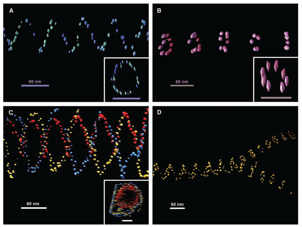
The above TEM images were only 2D projections of the 3D structures. From the parallel closed double lines, ellipsoidal rings, and occasional asymmetric zigzags observed in these images, we can deduce that these are true tubular structures with tube axes not perfectly perpendicular to the electron beam. In order to gain full appreciation of their 3D structural architectures, electron cryotomography was used to image these tubes. The native conformations of the tubes were better preserved by embedding them in vitreous ice. The samples were imaged at a series of tilted angles and then aligned and back-projected to reconstruct their 3D conformations (Fig. 3, A to D, figs. S9 to S14, and movies S1 to S7) (28). The stacked-ring tubes were clearly observed to be closed circular rings aligned in parallel. A number of single- and double-spiral tubes observed from different samples were revealed to be all left-handed. Figure 1D illustrates how this observation is counterintuitive and infers that both right- and left-handed tubes are equally possible. The preference of this left-handed chirality can be explained by the tendency of relaxed or underwound right-handed DNA double helices to form left-handed super-coils. This left-handed super-helicity may exist in each DNA tile and accumulates as the tiles self-assemble into the tile arrays. Thus, a left-handed twist naturally exists in the tile array, so that the superstructure formed prefers to have a left-handed chirality.
Fig. 3.
Representative 3D structures of nanoparticle tubes reconstructed from cryoelectron tomographic imaging. (A) One view of the tomogram of a single-spiral tube of 5-nm AuNPs. The inset shows a top view from the axis of two helical turns of the spiral tube; scale bar, 60 nm. (B) Tomogram of a stacked-ring tube of 5-nm particles. The inset shows a top view from the axis of a single ring from the stacked-ring tube; scale bar, 60 nm. (C) Tomogram of a double-spiral tube of 5-nm AuNPs with a single spiral of 5-nm nanoparticles inside each coded with a different color. The inset shows a top view from the axis of the double-wall spiral tube; scale bar, 60 nm. (D) Tomograph showing the splitting of a wider single-spiral tube into two narrower stacked-ring tubes of 10-nmAuNPs. All of the spiral tubes show a left-handed chirality. A weakly colored depth cue was applied to each view. The elongated appearance of the gold bead in the top views of the tubes is an effect of limited tilts in the tomography data collection. Movies of electron tomographic reconstruction corresponding to these structures are available in (28).
In addition to the left-handed chirality, we also observed an interesting double-walled DNA nanotube (Fig. 3C) formed by a single-spiral AuNP nanotube inside of a double-spiral AuNP nanotube; their periodicities are well aligned. A closer examination of this image showed that the right ends of the two tubes share a common layer, which may indicate that the growth of an internal or external secondary tube can be initiated from a primary tube defect.
Various types of tube conformation transitions were evident in both TEM and tomograms (Fig. 3D and figs. S15 and S16) (28). For example, continuous transitions from stacked rings to spiral tubes and vice versa can be discerned. Splitting of a single tube into two tubes of smaller diameters was also observed. Such transitions can involve any type of tube structure and can be explained either as conformational transitions during the tube growth or end-to-end joining of different tubes during and/or after the growth. This end-to-end joining is thermodynamically driven by the reduction in the number of unpaired sticky ends existing at the ends of the tubes after the nucleation stage. This type of tube-end joining can still occur with only partially matched sticky ends for the end tiles. In addition, the flexibility of the tile arrays and the presence of defects can also induce transitions from one type of tube to another during tube growth.
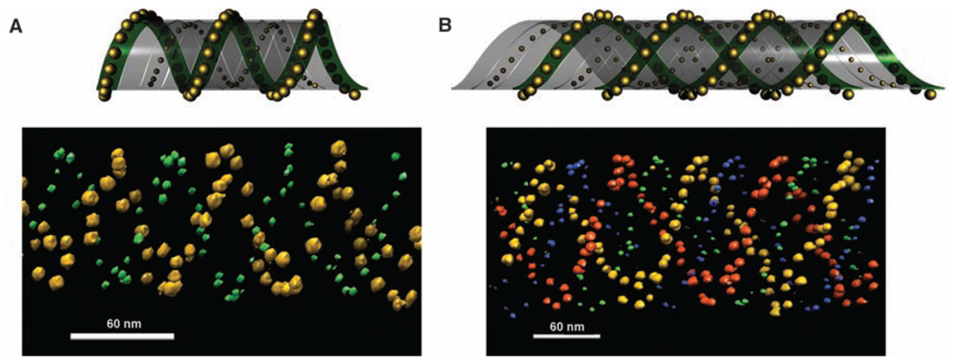
To increase the complexity of the 3D architecture, we placed 5- and 10-nm particles on opposite sides of the array on the A and C tiles, respectively. Electron tomographic images (Fig. 4) demonstrate such dual-labeled AuNP tube architectures. The image shown in Fig. 4A contains a single spiral of 5-nm AuNPs wrapped around a single spiral of 10-nm AuNPs (an architecture resembling a double helix). The image shown in Fig. 4B contains a double spiral of 5-nm AuNPs wrapped around a double spiral of 10 nm AuNPs (an architecture resembling a quadruplex). From the design, it is expected that the steric repulsion force among the 10-nm particles is greater than that among the 5-nm AuNPs so that the tubes would tend to have the 5-nm AuNPs wrapped inside and the 10-nm AuNPs displayed outside. However, when these tube samples were imaged by cryo-EM (Fig. 4, A and B) in which the native conformations of the tubes were preserved, the two AuNP sizes seemed to stay at about the same layer. It is possible that the 5-nm AuNPs repel one another sufficiently that they are squeezed outward through the gaps between the arms of the two DNA crossovers.
Fig. 4.
The tubes formed with 5- and 10-nm AuNPs placed on opposite surfaces of the DNA tile array. (A and B) The top panels are schematic side and top views of the binary particle tube architectures; the bottom panels are corresponding representative electron tomographic images clearly showing the 3D architectures. Movies of electron tomographic images corresponding to these structures are available in (28).
These types of AuNP superstructures and 3D complexities reflect the kind of complex architectures that naturally existing systems display (for example, diatoms) but with artificial control of precision at nanometer scales. By further engineering the tile structures, it should be possible to place different sizes or types of nanoparticles in or outside of the tubes. For example, self-assembled nanoinductors could be constructed when magnetic nanoparticles are placed inside of spiral wires made of metallic nanoparticles, which might represent a substantial advancement in small-scale device applications.
Supplementary Material
Footnotes
Supporting Online Material
www.sciencemag.org/cgi/content/full/323/5910/112/DC1
Material and Methods
Fig. S1 to S21
Table S1
Movies S1 to S7
References and Notes
- 1.Simon U. In: Nanoparticles: From Theory to Application. Schmid G, editor. Germany: Wiley-VCH, Weinheim; 2004. pp. 328–362. [Google Scholar]
- 2.Alivisatos AP, et al. Nature. 1996;382:609. doi: 10.1038/382609a0. [DOI] [PubMed] [Google Scholar]
- 3.Fu A, et al. J. Am. Chem. Soc. 2004;126:10832. doi: 10.1021/ja046747x. [DOI] [PubMed] [Google Scholar]
- 4.Deng Z, Tian Y, Lee S-H, Ribbe AE, Mao C. Angew. Chem. Int. Ed. 2005;117:3648. doi: 10.1002/anie.200463096. [DOI] [PubMed] [Google Scholar]
- 5.Le JD, et al. Nano Lett. 2004;4:2343. [Google Scholar]
- 6.Zhang J, Liu Y, Ke Y, Yan H. Nano Lett. 2006;6:248. doi: 10.1021/nl052210l. [DOI] [PubMed] [Google Scholar]
- 7.Zheng J, et al. Nano Lett. 2006;6:1502. doi: 10.1021/nl060994c. [DOI] [PMC free article] [PubMed] [Google Scholar]
- 8.Sharma J, Chhabra R, Liu Y, Ke Y, Yan H. Angew. Chem. Int. Ed. 2006;45:730. doi: 10.1002/anie.200503208. [DOI] [PubMed] [Google Scholar]
- 9.Aldaye F, Sleiman HF. Angew. Chem. Int. Ed. 2006;45:2204. doi: 10.1002/anie.200502481. [DOI] [PubMed] [Google Scholar]
- 10.Aldaye F, Sleiman HF. J. Am. Chem. Soc. 2007;129:4130. doi: 10.1021/ja070017i. [DOI] [PubMed] [Google Scholar]
- 11.Lee JH, et al. Angew. Chem. Int. Ed. 2007;46:9006. doi: 10.1002/anie.200702569. [DOI] [PubMed] [Google Scholar]
- 12.Xu X, Rosi NL, Wang Y, Huo F, Mirkin CA. J. Am. Chem. Soc. 2006;128:9286. doi: 10.1021/ja061980b. [DOI] [PMC free article] [PubMed] [Google Scholar]
- 13.Sharma J, et al. Angew. Chem. Int. Ed. 2008;47:5157. doi: 10.1002/anie.200801485. [DOI] [PMC free article] [PubMed] [Google Scholar]
- 14.Sharma J, et al. J. Am. Chem. Soc. 2008;130:7820. doi: 10.1021/ja802853r. [DOI] [PubMed] [Google Scholar]
- 15.Nykypanchuk D, Maye MM, van der Lelie D, Gang O. Nature. 2008;451:549. doi: 10.1038/nature06560. [DOI] [PubMed] [Google Scholar]
- 16.Park S, et al. Nature. 2008;451:553. doi: 10.1038/nature06508. [DOI] [PubMed] [Google Scholar]
- 17.Mathieu F, et al. Nano Lett. 2005;5:661. doi: 10.1021/nl050084f. [DOI] [PMC free article] [PubMed] [Google Scholar]
- 18.Park SH, et al. Nano Lett. 2005;5:693. doi: 10.1021/nl050108i. [DOI] [PubMed] [Google Scholar]
- 19.Douglas SM, Chou JJ, Shih WM. Proc. Natl. Acad. Sci. U.S.A. 2007;104:6644. doi: 10.1073/pnas.0700930104. [DOI] [PMC free article] [PubMed] [Google Scholar]
- 20.Yan H, Park SH, Finkelstein G, Reif JH, LaBean TH. Science. 2003;301:1882. doi: 10.1126/science.1089389. [DOI] [PubMed] [Google Scholar]
- 21.Rothemund PWK, et al. J. Am. Chem. Soc. 2004;126:16344. doi: 10.1021/ja044319l. [DOI] [PubMed] [Google Scholar]
- 22.Mitchell JC, Harris JR, Malo J, Bath J, Turberfield AJ. J. Am. Chem. Soc. 2004;126:16342. doi: 10.1021/ja043890h. [DOI] [PubMed] [Google Scholar]
- 23.Liu D, Park SH, Reif JH, LaBean TH. Proc. Natl. Acad. Sci. U.S.A. 2004;101:717. doi: 10.1073/pnas.0305860101. [DOI] [PMC free article] [PubMed] [Google Scholar]
- 24.Liu H, Chen Y, He Y, Ribbe AE, Mao C. Angew. Chem. Int. Ed. 2006;45:1942. doi: 10.1002/anie.200504022. [DOI] [PubMed] [Google Scholar]
- 25.Yin P, et al. Science. 2008;321:824. doi: 10.1126/science.1157312. [DOI] [PubMed] [Google Scholar]
- 26.Ke Y, Liu Y, Zhang J, Yan H. J. Am. Chem. Soc. 2006;128:4414. doi: 10.1021/ja058145z. [DOI] [PubMed] [Google Scholar]
- 27.Liu F, Sha R, Seeman NC. J. Am. Chem. Soc. 1999;121:917. [Google Scholar]
- 28.Materials and methods are available as supporting material on Science Online.
- 29.We thank for financial support the National Science Foundation (NSF) and Army Research Office (ARO) (to Y.L.), the Air Force Office of Scientific Research, Office of Naval Research, NSF, Alfred P. Sloan Fellowship, ARO, and NIH (to H.Y.), and Technology and Research Institute Funds funds from Arizona State University (to H.Y. and Y.L.). Some of the work presented here was conducted at the National Resource for Automated Molecular Microscopy, which is supported by NIH though the National Center for Research Resources’ P41 program (RR17573). We thank C. Potter and B. Carragher for helpful discussion and technical advice on the electron tomography work. IMOD software (Boulder Laboratory for 3D Electron Microscopy of Cells, Boulder, CO) used for tomographic reconstruction is supported by NIH grant P41 RR000592. 3D graphic images were produced using the University of California, San Francisco (UCSF) Chimera package from the Resource for Biocomputing, Visualization, and Informatics at UCSF (supported by NIH grant P41 RR-01081). We thank M. Palmer for technical assistance. We acknowledge the use of the EM facility in the School of Life Sciences at Arizona State University. We thank C. Lin for assistance in schematic figure drawings and Y. Ke for assistance in creating movies from the tomography reconstructions. We thank C. Flores for help proofreading the manuscript.
Associated Data
This section collects any data citations, data availability statements, or supplementary materials included in this article.


