Abstract
In the field of enzymatic catalysis, creating activity from a non catalytic scaffold is a daunting task. Introduction of a catalytically active moiety within a protein scaffold offers an attractive means for the creation of artificial metalloenzymes. With this goal in mind, introduction of a biotinylated d6-piano-stool complex within streptavidin (SAV) affords enantioselective artificial transfer-hydrogenases for the reduction of prochiral ketones. Based on an X-ray crystal structure of a highly selective hybrid catalyst, displaying significant disorder around the biotinylated catalyst [η6-(p-cymene)Ru(Biot-p-L)Cl], we report on molecular dynamics simulations to shed light on the protein–cofactor interactions and contacts. The results of these simulations with classical force field indicate that the SAV-biotin and SAV-catalyst complexes are more stable than ligand-free SAV. The point mutations introduced did not affect significantly the overall behavior of SAV and, unexpectedly, the P64G substitution did not provide additional flexibility to the protein scaffold. The metal-cofactor proved to be conformationally flexible, and the S112K or P64G mutants proved to enhance this effect in the most pronounced way. The network of intermolecular hydrogen bonds is efficient at stabilizing the position of biotin, but much less at fixing the conformation of an extended biotinylated ligand. This leads to a relative conformational freedom of the metal-cofactor, and a poorly localized catalytic metal moiety. MD calculations with ab initio potential function suggest that the hydrogen bonds alone are not sufficient factors for full stabilization of the biotin. The hydrophobic biotin-binding pocket (and generally protein scaffold) maintains the hydrogen bonds between biotin and protein.
Electronic supplementary material
The online version of this article (doi:10.1007/s10822-010-9369-x) contains supplementary material, which is available to authorized users.
Keywords: (Strept)avidin, Biotinylation, Enantioselectivity, DFT, Classical and ab initio force field molecular dynamics
Introduction
The optimization of the catalytic performance for a particular reaction and substrate is one of the most active branches of chemistry [1, 2]. Catalyst optimization frequently relies on high-throughput screening methods, which omit the tedious task of detailed experimental and computational investigation of each catalyst-candidate [3–5]. In the context of enantioselective transformations, homogeneous and enzymatic catalysis occupy a prominent place. With the aim of combining attractive features of both techniques, artificial metalloenzymes, which rely on the introduction of a catalytically active organometallic moiety in a protein scaffold [6] have recently witnessed a revival [7–10]. The presence of the protein host modifies the local environment of the metal center, and this either generates or influences the catalytic activity provided by the metal center [2, 11–14]. Proteins, which supply a chiral environment around an achiral metal moiety may induce enantioselectivity, by interacting with the metal and/or the prochiral substrate via weak interactions. In recent years, several complementary approaches have been successfully pursued towards the creation and optimization of artificial enzymes including metalloenzymes [14–22].
Avidin and streptavidin (SAV) ((strept)avidin refers to avidin or streptavidin indiscriminately hereafter) are proteins well known for their biotin-binding properties. They possess a tetrameric structure with four biotin-binding pockets. The affinity of biotin for avidin and streptavidin ranks amongst the strongest non-covalent interactions found in Nature: 1013 M−1 and 1015 M−1, respectively [23–25]. This feature has led to a variety of applications of the (strept)avidin–biotin technology in biochemistry and medicine: biosensors, immunoassays, separation, signal amplification and protection techniques [23, 26, 27]. The strong binding of biotin to (strept)avidin results from the cooperative combination of several factors: hydrogen bonding network formation in the cavity, hydrophobic effects provided by surrounding aromatic residues [28–30], protein reorganization (estimated to be the main unfavorable process [31]) or loss of translational and rotational entropy of the ligand. The hydrophobic pocket provided by the cage of aromatic residues (avidin: Tyr and Trp, streptavidin: Trp) provides significant portion of the binding energy, and its action is only slightly affected by substitution of the Trp residues with 4-, 5- or 6-fluorotryptophan [30]. Recently, cooperativity of hydrogen bonding and role of cavity desolvation for the biotin-binding were studied by classical molecular dynamics and ab initio calculations [32, 33], revealing the important role of the charged Asp128 residue which polarizes the ureido moiety in the biotin. Since the stability of the biotin or biotinylated ligand in the binding pocket of streptavidin is strongly affected by the presence of the hydrogen bonding network, one of arising questions is the dynamics of this network. This problem will be addressed in the current study by molecular dynamics techniques.
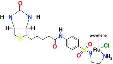
The main aim of this study is an investigation of the host (strept)avidin—guest (cofactor) interactions. Two kinds of biotinylated cofactors binding to streptavidin and its mutants were studied. Firstly, the streptavidin–biotin system, which served as an example of the prototypical protein–ligand complex, was investigated. This part of the simulations was used to establish the dynamics of the protein and the hydrogen bonding network at the biotin-binding site, as mentioned above. Secondly, the streptavidin-[η6-(p-cymene)Ru(Biot-p-L)Cl] interactions (Biot-p-L is a shorthand notation for the organic part of the cofactor pictured in Scheme 1) were examined. The [η6-(p-cymene)Ru(Biot-p-L)Cl] cofactor attached to the protein host is an artificial metalloenzyme with a high catalytic activity and selectivity in enantioselective transfer hydrogenation of prochiral substrates [21] following the general asymmetric catalytic mechanism described by Noyori et al. [34]. Special attention was devoted to the flexibility of the biotinylated cofactors, which may be important in the performance of the asymmetric catalysis [21, 35]. At least the catalytic part of the cofactor is exposed to the solvent, so that the transfer hydrogenation can be efficiently catalyzed. This fact means that the disorder in the position of the cofactor can be expected, and the crucial question is if this disorder can be estimated and controlled. Increased conformational flexibility of the cofactors leads to a statistical averaging of the environment of the catalytic center. This fact hinders the rational search for optimal conditions for asymmetric catalysis. The recent X-ray crystal structure determination of the S112K-streptavidin-[η6-(benzene)Ru(Biot-p-L)Cl] complex [36] has revealed that the cofactor is disordered: the biotin part is well-localized, while the phenylsulfonyl and ethylenediamine moieties are disordered. As a result, the occupancy of the experimentally determined position of the metal and its first coordination sphere is only 20%. This can be attributed to one of several possible causes: dissociation of the cofactor from the protein during crystallization; steric hindrance between two bulky cofactors in two neighboring binding pockets of tetrameric streptavidin (experimental Ru–Ru distance is only 4.44 Å for a full occupancy); or—conformational flexibility of the cofactor [36]. Most probably, the metal moiety is located on a soft potential energy surface with very little preference for any of numerous localizations. If there were only a few well-defined positions of the metal, the X-ray experiment would be able to locate them. Another interesting experimental fact is that even if the solution contains racemic form of the cofactor, the crystal structure of the S112K-SAV-[η6-(benzene)Ru(Biot-p-L)Cl] complex contains the cofactor with S configuration at the ruthenium, which is predicted according to Noyori’s mechanism, to afford the (S)-reduction product. Gratifyingly this corresponds to the observed enantiomer of the product [36]. Such enantioselective binding of the cofactor deserves further examination. In this context, a thorough insight in the protein–cofactor interactions at the atomistic level is required. Thus, we employed molecular dynamics based on classical and ab initio force fields to (i) include a statistical sampling of the configurational space of complex systems, (ii) examine in detail the hydrogen bonding network between biotin and the binding site, and (iii) analyze the evolution of the molecular properties as a function of time. We have chosen one of the best-performing catalysts, [η6-(p-cymene)Ru(Biot-p-L)Cl], as the metal-containing coenzyme. This ligand and its analogues have proven active, but not enantioselective, transfer hydrogenation catalysts in solution, and addition of SAV was needed to generate enantiomeric excess [35]. Our selection of streptavidin mutants encompasses mutations in the vicinity of the metal and mutations affecting the stability of some structural elements of the protein involved in biotin-binding.
Scheme 1.
Biotinylated cofactor, [η6-(p-cymene)Ru(Biot-p-L)Cl]
Computational methodology
Molecular dynamics simulations carried out in the framework of this study consist of two parts: MD based on the classical and DFT force fields. Various details of these calculations will be provided below.
Procedures related to the classical force field MD simulation
Classical force field molecular dynamics (MD) simulations were performed for tetrameric core streptavidin (residues 13–135) in the following variants: apo (cofactor-free) WT SAV and mutants—S112A, S112K and P64G (see Fig. 1). Furthermore, the complexes of WT SAV and its mutants with biotin and with [η6-(p-cymene)Ru(Biot-p-L)Cl] were investigated. Both R and S configurations at the ruthenium atom were considered. Genetic optimization of SAV proved to be an efficient means to improve both activity and selectivity. In this context, S112A was found to be among the most promising mutants with respect to the obtained yield and (R)-enantioselectivity [21]. In contrast, S112K affords (S)-reduction products. The P64 residue can indirectly influence the behavior of the L7,8 loop of streptavidin (residues 112–122) and the mutation of P64 to G exchanges a rigid residue with a flexible one. Finally, the P64G mutant had a significantly improved activity compared to WT SAV [35]. The X-ray data for the tetrameric streptavidin–biotin complex (PDB entry: 2IZF) at 1.58 Å resolution was used as a template for initial atomic coordinates [37]. Two chains of the SAV initial model (2IZF PDB code) were shorter by two residues (K134 and P135) than the other two chains, which explains why the net charges of the protein models were not multiples of 4 (see section “Classical force field molecular dynamics models preparation”). The models for simulation were prepared without equalizing the chain lengths, that is deleting or adding K134 and P135 to the relevant chains. Our decision (not to equalize the chains of the X-ray 2IZF PDB structure) was made because this structure presents even more general approximation: it describes the core streptavidin (13–135) instead of the full-length SAV. Because of the flexibility of the terminal residues, the structure of pure full-length streptavidin is not determined with the desired accuracy. Therefore, we chose to follow closely the experimental core streptavidin structure. Most of the reported data of the classical force field simulation are based on the whole-structure data (e.g. RMSD, RGYR, SASA, RMSF), and even when the interatomic distances are disussed, we prepared the analysis in such a way that the reported data do not depend on the choice of the particular chain. The crystal water present in the experimental PDB structure was removed to avoid possible short contacts during inclusion of large cofactors into the binding pocket (see below). This procedure was also consistently used for non-loaded protein simulations. Typical protonation states were assumed: for residues Arg, Lys-positive, while Asp, Glu-negative. Additionally, on the basis of visual examination of the environment of the two histidine residues (87 and 127) of SAV, and on pH-dependent structural studies of the SAV protein [37], His87 was assumed to be positive and His127 residue was taken to be neutral and protonated at the δ nitrogen only. The S112A, S112K and P64G mutants were prepared by single residue substitution in each of the monomers of tetrameric SAV.
Fig. 1.
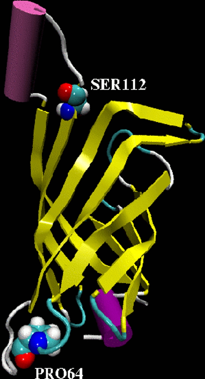
Fragment of WT SAV protein. One monomer was chosen for clarity to show sites of mutations (CPK rendering) considered in this study. Ser112 was mutated to Ala and Lys, respectively, and Pro64 to Glycine
Cofactor preparation
In the current study two cofactors interacting with WT SAV and its mutants were taken into account: (i) biotin, (ii) the biotinylated catalyst [η6-(p-cymene)Ru(Biot-p-L)Cl] with either (R) or (S) configuration at the metal. The cofactors are non-standard, therefore it was necessary to proceed with force field parametrization for some missing parameters, not present in the force field, according to the quantum–mechanical data. Geometry optimization of the cofactors was performed using Density Functional Theory (DFT) [38, 39]. Three-parameter hybrid formula consisting of nonlocal exchange potential proposed by Becke [40] with the nonlocal correlation functional of Lee, Yang and Parr [41] denoted as B3LYP in conjugation with the SDD basis set (including pseudopotential to replace core electrons of the heavy atoms) [42] was used. Subsequently, harmonic frequencies were calculated to confirm that the obtained structures correspond to minima on the potential energy surface (PES). Partial atomic charges were calculated according to Merz–Kollman–Singh scheme [43]. A necessary task at this point, validation of the additional force field parameters for the cofactor, carried out against DFT and MP2 quantum-chemical data, is presented in the Online Resource 1. Electrostatic potential (ESP) distribution around the isolated molecule of biotinylated [η6-(p-cymene)Ru(Biot-p-L)Cl] catalyst and around the catalyst placed in the model of the binding pocket of S112 SAV was also calculated for visual inspection of the reactive (electro- or nucleophilic) parts of the cofactor. The model of the binding pocket used in the ESP study consisted of the following residues: Asn23, Leu25, Ser27, Tyr43, Ser45, Val47, Asn49, Ala86, Ser88, Thr90, Leu110, Lys112, Lys121, Asp128, and Lys121′ from a neighboring monomer of the tetrameric S112K SAV. These residues were selected on the basis of their proximity to the cofactor, but the hydrophobic tryptophan moieties were not taken into account, since their stabilizing effect is not ESP-related, but corresponds to the van der Waals forces. Calculated structural and electronic structure parameters were further used to complete the molecular mechanics force field. This part of the simulations was carried out using the Gaussian03 suite of programs [44].
Classical force field molecular dynamics models preparation
The first set of models consisted of the tetrameric WT SAV and its mutants-S112A, S112K and P64G. The second one contained the complexes between WT SAV and its mutants with biotin, while for the third set of models, [η6-(p-cymene)Ru(Biot-p-L)Cl] with either (R) or (S) configuration at the metal served as the cofactor. In the last mentioned set of models, atomic coordinates of biotin present in the experimental X-ray structure of the biotin-SAV complex [37] served as anchor points on which the biotinylated cofactor was built. In the second and third sets of models, which contain ligands, all four ligand-binding sites were always loaded with the cofactor. However, due to the lack of symmetry in the PDB structure which server as the base model, the four cofactors were built by the LEAP module with slightly different geometry, providing locally different initial starting points for further simulation. Subsequently, all the prepared models were placed in rectangular boxes of ca. (85 × 88 × 94 Å) dimensions filled with water (ca. 17,000–17,060 molecules, depending on the model). Periodic boundary conditions (PBCs) were applied to simulate the bulk solution. The net charge of the studied complexes was neutralized using sodium ions. The net charge of the protein is −6 (−2 for the S112K mutant), which is not a multiple of 4—see the top of the section “Procedures related to the classical force field MD simulation” for explanation. The Amber ff99SB force field [45] was employed for the organic part and counterions, while water molecules were described by TIP3P model [46]. The force field parameters for the cofactor, listed in Online Resource 1, were based on quantum–mechanical calculations (bonds, angles) or similarity with existing parameters. Non-bonded van der Waals and short range electrostatic interactions (calculated in direct space) were switched off at 10 Å. The particle mesh Ewald method was applied to evaluate the long range electrostatic interaction [47–49]. The models were prepared with assistance of the LEAP program implemented in the AMBER9 suite of programs [50], which also served as a tool for adding hydrogen atoms in positions defined by the residue structures and topology files, and with the assumed protonation states discussed in section “Procedures related to the classical force field MD simulation”.
Classical force field molecular dynamics simulations
First, as an initial part of the MD simulations, the energy minimization of 200 steps (after 10 steps of steepest descent, conjugate gradient technique was switched on) was carried out to remove short contacts between the studied systems and solvent. Secondly, all investigated systems underwent NVT simulations, which were taken as an equilibration time. The systems were heated to 300 K using a stepwise protocol (75 ps of linear heating from 0 to 100 K, 75 ps equilibration at 100 K, and further analogously with 100 K increments to 300 K, at which temperature the system was kept for ca. 1.2 ns) and thermostatted using Langevin thermostats [51]. A time-step of 1.5 fs was employed and the total simulation time for equilibration consisted of 1.5 ns runs. Finally, for the production simulation we switched to NPT ensemble (regulated with Langevin thermostats and barostats set at 300 K and 1 atm conditions [51, 52]) and the data were collected for more than 50 ns for each of the investigated systems. Each simulation of 50 ns, run on 64 cores (Intel Xeon EM64T 2.33 GHz CPU), took ca. 15–18 days of wall time. Bonds involving hydrogen atoms were kept at fixed length using the SHAKE algorithm [53]. At the level of accuracy provided by classical potential functions, this fact should have negligible impact on the hydrogen bonding network. The AMBER9 suite of programs was employed for this part of simulations [50]. The post-processing of the obtained trajectories was performed using the VMD program [54].
Ab initio force field Born–Oppenheimer molecular dynamics simulations
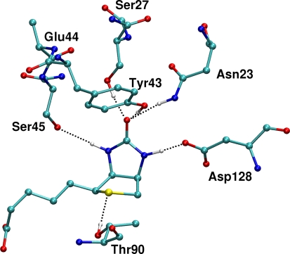
Molecular dynamics simulations in vacuo with ab initio force field were carried out on the basis of the Born–Oppenheimer scheme assuming full evaluation of the electronic structure of the system at each time-step [55, 56]. This part of simulations was performed using the CP2K program [57] which uses a dual Gaussian—plane-wave basis set to describe the DFT Kohn–Sham orbitals and electron density. As a model of the hydrogen bonding part of the binding pocket the following residues were considered: Thr90 (with OH group directed towards the sulfur atom of biotin), Asp128 (with COO− directed towards one of the NH group of biotin), Ser27, Ser45, Glu44, Tyr43 and Asn23. Glu44 is not directly involved in the biotin-protein interactions, but this residue was included as it connects Tyr43 and Ser45. The computational model of the binding pocket of WT SAV and biotin complex is presented in Fig. 2. Starting coordinates of the relevant atoms were extracted from the initial structure of the classical model. High computational demands of this type of MD (see below) excluded possibility of repeating the run several times with different initial coordinates. Taking the experimental solid-state data as the source for initial coordinates was considered by us as the safest choice; snapshots from the classical simulations might accidentally provide an instantaneous unfavorable arrangement of the ligand versus the residues. The studied complex was placed in a cubic box with an edge of 24 Å. As an initial part of the simulations, the energy minimization was performed with constraints placed on carbon or nitrogen atoms of the terminal groups simulating the extended protein (see Figure SI21 of the Online Resource 2). Kinetic energy cutoff of 240 Ry was applied for the plane-wave expansion of the electron density, and triple-zeta-valence + polarization (TZVP) Gaussian basis set was employed to provide localized description of the electronic structure of the studied complex. Core electrons were represented by GTH pseudopotentials [58–60]. A gradient-corrected exchange–correlation DFT functional denoted as BLYP was used [41, 61]. Subsequently, the Born–Oppenheimer molecular dynamics was performed using NVT ensemble. The MD simulations were performed at 300 K and Nosé-Hoover thermostat was used to control the assigned conditions [62, 63]. The time-step of 0.75 fs was used during the simulations. Total data collection time was ca. 8 ps, and the wall clock time for the simulation using 32 Intel Xeon EM64T CPU cores was ca. 25 days. The initial 1,000 steps of the MD run (0.75 ps) were taken as an equilibration time and were not considered during the data analyses. The geometry constraints mentioned above for the optimization step were also kept during the MD simulation. Ab initio force field MD enabled us to prepare a very accurate description of the time evolution of the hydrogen bonding network, which is one of the key factors for exceptional stability constant of the biotin-binding in the pocket, and thus—for the versatility of biotin-(strept)avidin technology. Analysis of the time evolution of the selected contacts will provide information on the dynamics of the binding pocket, and the importance of particular residues for binding can be potentially estimated. Graphical presentation of the results was prepared with the VMD [54] and Gnuplot [64] programs.
Fig. 2.
Biotin surrounded by key residues forming hydrogen bonding network—a model for ab initio Born–Oppenheimer molecular dynamics. For clarity, only those hydrogen atoms which participate in the hydrogen bonds are depicted. A different view is presented in Figures SI20 and SI21 of the online resource 2
Results and discussion
Classical force field and DFT Born–Oppenheimer molecular dynamics methods were used to scrutinize the nature and describe the details associated with the streptavidin–biotin/[η6-(p-cymene)Ru(Biot-p-L)Cl] (with either (R) or (S) configuration at the metal center) interactions at the atomistic level. Special attention was devoted to the stability of the investigated complexes and the network of intermolecular hydrogen bonds, which are the most important factors for the rational design of artificial metalloenzymes. Electrostatic potential served as an additional parameter describing the cofactor-protein interaction. The current study is aimed not only at elucidating the cofactor dynamics, but also at estimating the effect of mutations and the influence of the cofactor on the stability of the protein. Additionally it is useful to compare the advantages and disadvantages of both types of MD simulations. Their CPU-demanding nature and long real-time length (on the scale of 2–3 weeks for a single run, which in fact must be multiplied by at least two due to various policies of CPU resource usage, queueing systems etc.) call for careful desinging the desired information to be gathered from each run. This is true especially concerning the DFT-based MD, for which it is important to choose a suitable model for simulation. Being aware of the fact that dispersion effects of the hydrophobic cage play significant role in the stability of the cofactor-SAV complex, we did not attempt to model these interactions using DFT. We turned our attention to the dynamic nature of the stronger interactions, i.e. hydrogen bonds and Coulomb attraction of charged residues. With this in mind, we expected that the hydrogen bonding network in a small model (without rigid protein scaffold and stabilizing hydrophobic interactions, in the gas-phase model limit) will be very flexible at the DFT level. On the other hand, the use of ab initio potential energy surface allowed us to overcome the classical nature of standard force fields (e.g. DFT-based MD allows possibility of proton transfer). Thus, the simulations based on classical and ab initio potential function are used by us in a complementary fashion: the former, equipped with empirical corrections for weak interactions difficult to describe at the DFT level, provide picture of the system stability at large scale unaccessible for the ab initio schemes, while the latter allow us to observe detailed behavior of hydrogen bonding network without the support of the protein scaffold.
Classical force field molecular dynamics
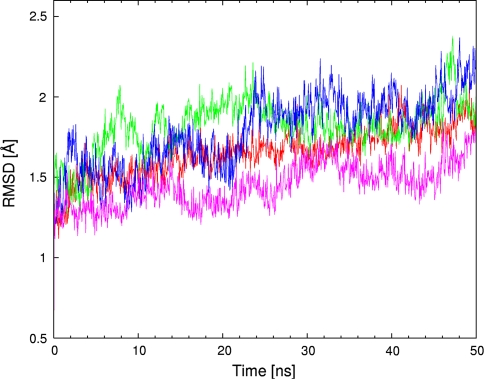
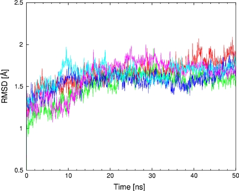
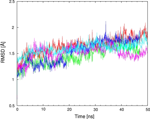
MD simulations based on classical potential function are used to provide a description of the whole biomolecular streptavidin–biotin and selected streptavidin-biotinylated piano-stool catalyst complexes in water. The obtained trajectories were analyzed using various post-processing estimators. The first of them is Root Mean Square Deviation (RMSD) of the protein backbone with reference to the initial structure. A series of three Figs. 3, 4 and 5 presents the time evolution of the RMSD for streptavidin and its mutants in three respective configurations: (i) apo (cofactor-free), (ii) loaded with biotin and (iii) containing biotinylated piano-stool catalyst: [η6-(p-cymene)Ru(Biot-p-L)Cl]. For the apo structure (Fig. 3), the most stable dynamics, as revealed by the smallest fluctuations of the RMSD, is recorded for the WT SAV. While the P64G mutant has overall lower RMSD values, the time evolution (scheme of RMSD fluctuations) is more dynamic than for the WT SAV. On the other hand, structures of both S112A and S112K mutants seem to fluctuate more than the two other variants. This fact is reproduced in the mean values and standard deviations of the RMSD (Table 1). We hypothesize that the fluctuations of the apo-structures are larger than with either biotin- or metal-cofactor-loaded SAV (Figs. 4 and 5 include RMSD time evolution for WT SAV as a reference). This may be due to the complementarity of the cofactor-protein interactions, which leads to destabilization of the protein in the absence of the cofactor. The models for simulation were prepared on the basis of the biotin-loaded experimental structure. Since the adjustment of important structural elements, e.g. loops, to the absence/presence of the biotin can take well over hundreds of nanoseconds (see below), we could not expect full equilibration of the biotin-free proteins. Therefore, the RMSD fluctuations are much larger in Fig. 3, which describes biotin-free simulations. This effect is much less pronounced in Figs. 4 and 5, where proteins adjust much better to the mutations and changed cofactor. However, the relative stability of the cofactor-loaded SAV structures cannot be easily estimated either from the RMSD graphs or the statistical data included in Table 1. The structural fluctuations of the backbone for all of the cofactor-loaded systems follow the apo-WT SAV reference graph more closely than do the apo mutants. This is another manifestation of the stabilizing role of the cofactors. Moreover, data from Table 1 suggests that there is a little difference between RMSD values for a given protein variant loaded with either biotin or the metal catalyst (e.g. 1.66 ± 0.13 Å for biotin-WT SAV and 1.61 ± 0.12 Å for cofactor-WT SAV). Usually the backbone fluctuations are smaller for the cofactor-loaded protein in comparison to the respective biotin-SAV system. This suggests that the presence of the cofactor is not destabilizing the protein. Experimental study [36] of a structurally related cofactor, [η6-(benzene)Ru(Biot-p-L)Cl], anchored in S112K SAV suggests that the protein structure is not disturbed and the superimposition of WT SAV and cofactor-bearing S112K mutant results in only 0.28 Å RMSD between backbone Cα carbon atoms of the two systems. Our classical force field simulations also reproduce the exceptional stability of the streptavidin backbone—apart from the RMSD discussed above, superimpositions of the final structures after the MD runs (see Figures SI1–SI6 of the Online Resource 2) indicate that the deviations are relatively small.
Fig. 3.
Root mean square deviation (RMSD, in Å) of the protein backbone as a function of MD simulation time (in ns) for WT SAV and its mutants. WT SAV is marked in red, S112A in green, S112K in blue and P64G in purple
Fig. 4.
Root mean square deviation (RMSD, in Å) of the protein backbone as a function of MD simulation time (in ns) for WT SAV, WT SAV-Biotin and its mutants with Biotin. WT SAV is marked in red, WT SAV-Biotin in cyan, S112A-Biotin in green, S112K-Biotin in blue and P64G-Biotin in purple
Fig. 5.
Root mean square deviation (RMSD, in Å) of the protein backbone as a function of MD simulation time (in ns) for WT SAV, WT SAV-[η6-(p-cymene)Ru(Biot-p-L)Cl] and its mutants with [η6-(p-cymene)Ru(Biot-p-L)Cl]. WT SAV is marked in red, WT SAV[η6-(p-cymene)Ru(Biot-p-L)Cl] in cyan, S112A-[η6-(p-cymene)Ru(Biot-p-L)Cl] in green, S112K[η6-(p-cymene)Ru(Biot-p-L)Cl] in blue and P64G-[η6-(p-cymene)Ru(Biot-p-L)Cl] in purple
Table 1.
Selected structural parameters of the WT SAV and its mutants studied by classical molecular dynamics in apo forms and in complexes with biotin or metal-containing cofactor [η6-(p-cymene)Ru(Biot-p-L)Cl]
| RMSD ± SD [Å] | RGYR ± SD [Å] | |
|---|---|---|
| WT SAV | 1.67 ± 0.17 | 22.13 ± 0.07 |
| S112A SAV | 1.84 ± 0.19 | 22.19 ± 0.07 |
| S112K SAV | 1.81 ± 0.23 | 22.23 ± 0.09 |
| P64G SAV | 1.46 ± 0.15 | 22.10 ± 0.06 |
| Biotin-WT SAV | 1.66 ± 0.13 | 22.14 ± 0.06 |
| Biotin-S112A SAV | 1.50 ± 0.18 | 22.11 ± 0.06 |
| Biotin-S112 K SAV | 1.58 ± 0.12 | 22.10 ± 0.05 |
| Biotin-P64G SAV | 1.62 ± 0.21 | 22.03 ± 0.05 |
| Cofactor-WT SAV | 1.61 ± 0.12 | 22.13 ± 0.06 |
| Cofactor-S112A SAV | 1.45 ± 0.17 | 22.11 ± 0.05 |
| Cofactor-S112 K SAV | 1.53 ± 0.23 | 22.14 ± 0.06 |
| Cofactor-P64G SAV | 1.51 ± 0.13 | 22.02 ± 0.05 |
RMSD root mean square deviation of the atomic coordinates from the initial structure, RGYR mass-weighted radius of gyration, SD standard deviations
The RMSD reflects the deviations of the structure from the initial (reference) set of coordinates, but the direction of actual change is not reported by this parameter. For this particular purpose, we have calculated the mass-weighted radius of gyration (RGYR) according to the formula:
 |
where N is the number of atoms in the protein, m i and r i are mass and position of the i-th atom, and r m is the barycenter of the system. RGYR for a given system is proportional to its moment of inertia and reflects the expansion or contraction of the structure. Statistical averages and standard deviations of this parameter are gathered in Table 1, while Figures SI7–SI9 of the Online Resource 2 present its time evolution for the apo-structures and biotin- or metal-loaded proteins, respectively. The similarity between biotin- and cofactor-loaded proteins is even more visible than from the RMSD plots and statistics. More importantly, it is visible that the P64G substitution leads to consistently smaller average RGYR values, which means that the P64G SAV structure is on average slightly more contracted. The data for the other mutants do not show any clear dependencies, apart from the fact that the presence of either biotin or the metal-cofactor in the binding pocket is stabilizing the structure. The S112A and S112K mutants behave similarly to the WT SAV. These facts, consistent with the description based on the RMSD, show that the mutation of S112 is acting locally. More surprisingly, the P64G SAV variant is not more flexible than the WT SAV, especially if the large cofactor is present. It is possible that the additional flexibility introduced by the P64G mutation is quenched by the presence of bulky cofactors. As mentioned at the beginning of section “Computational methodology”, residue 64 can indirectly influence the behavior of the L7,8 loop of streptavidin (residues 112–122) and P64G mutation exchanges a rigid residue with a flexible one. This mutation had favorable impact on reduction of p-methylacetophenone by artificial metalloenzyme [35]. Analysis of RMSF and SASA, parameters describing backbone dynamics at a local scale and solvation of the protein, respectively, is presented in the Supporting Information. These parameters show that even the local dynamics is only slightly affected, and solvation shell of the protein is rather unaffected by the mutations.
Important events for the SAV function are loop openings. Both L3,4 (residues 35–46) and the aforementioned L7,8 (residues 112–122) are able to open and close, and this affects the binding of biotin. However, such events were not present in our simulations at the used time scale, even with the P64G mutant which was devised to provide additional flexibility to the L7,8 loop. The experimental time for this process is on the scale of hundreds of nanoseconds, much larger than that of our simulation. A molecular dynamics study on unbinding the biotin from the SAV pocket [65] used an external force to open the L3,4 loop and provide necessary initial conditions for further release of the ligand.
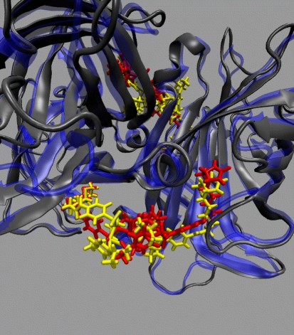
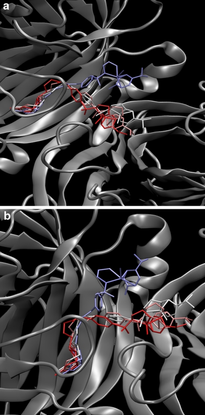
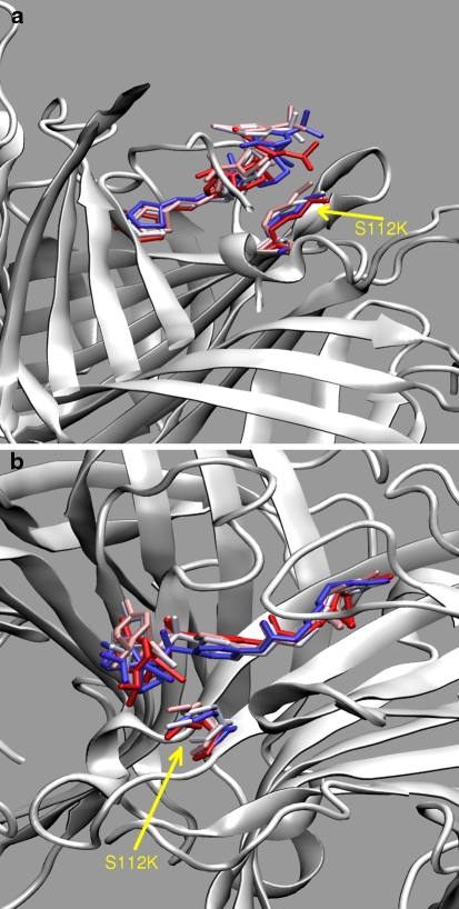
Next part of the discussion is devoted to the complexes containing [η6-(p-cymene)Ru(Biot-p-L)Cl] as cofactor. Both R and S configurations at the metal were considered. If not specifically noted, all the results throughout the paper refer to the (R)-configuration at ruthenium, which affords the observed (R)-reduction product of the transfer hydrogenation according to the mechanism of Noyori [34]. However, the secondary coordination sphere provided by the protein is ill-defined. This fact is not caused by the flexibility of the protein itself, which we have shown in the preceding paragraphs. The cofactor itself is conformationally labile, and only the biotin part is tightly held within the binding pocket of streptavidin. This leads to the behavior depicted in Fig. 6: the environment of the cofactor before and after the simulation is different, and this in turn can strongly influence the stereoselectivity of the reaction. Additional visualization of the cofactor flexibility is presented in Figs. 7 and 8 for WT SAV and S112K SAV, respectively. These Figures show that the S112K mutation decreases conformational flexibility of the cofactor. We will return to this fact shortly.
Fig. 6.
Superimposition of the cofactor-loaded WT SAV at the beginning (the protein indicated in blue and the ligands in red) and after (the protein indicated in gray and the ligands in yellow) the MD run. Positions of the two [η6-(p-cymene)Ru(Biot-p-L)Cl] cofactors, in the front and at the back, are also indicated. The apparent shift of the ureido ring of the cofactor is an artifact of the RMSD alignment procedure—note that the protein backbone is also shifted by the same vector after the MD run
Fig. 7.
Two representations of superposition of cofactor positions sampled at 10 ns intervals during classical MD simulation of WT SAV-[η6-(p-cymene)Ru(Biot-p-L)Cl] complex. Colors (from blue through white to red) indicate time sequence of the snapshots
Fig. 8.
Two representations of superposition of cofactor positions sampled at 10 ns intervals during classical MD simulation of S112K-[η6-(p-cymene)Ru(Biot-p-L)Cl] complex. The K112 residue is also marked. Colors (from blue through white to red) indicate time sequence of the snapshots
The experimental X-ray data for a related [η6-(benzene)Ru(Biot-p-L)Cl]-S112K system indicate that the Ru–Ru distance between neighboring cofactors is unrealistically short, 4.44 Å. This should lead either to partial occupation of the binding pockets or to the conformational disorder of the cofactors [36]. The time evolution of the Ru–Ru distances during classical force field simulations is presented in Figures SI16–SI19 of the Online Resource 2. These graphs indicate that the cofactors are able to avoid such short contacts, at the price of increased disorder of the structure. Interestingly, for all variants there are shorter or longer periods of stable metal–metal separation; the least structured cofactors are observed for the P64G SAV mutant, which was indeed devised to provide increased flexibility of the structure. An important observation is also that the pairs of cofactors of mixed stereochemistry (R–S pairs) seem to be less fluctuating than the R–R pairs, which is systematically visible in the distances averaged over the MD run: 7.48 ± 0.30 Å for the R–S pair and 6.45 ± 0.99 Å for the R–R case in the WT SAV simulation (see Figures SI16–SI19, where additionally data for the mutants is provided). It should be emphasized here that the host SAV was experimentally determined to have 1.4 eq. active sites with respect to the ruthenium cofactor [35], but the crystal structure of the SAV-cofactor complex shows that the biotin moiety is present in all binding sites [36].
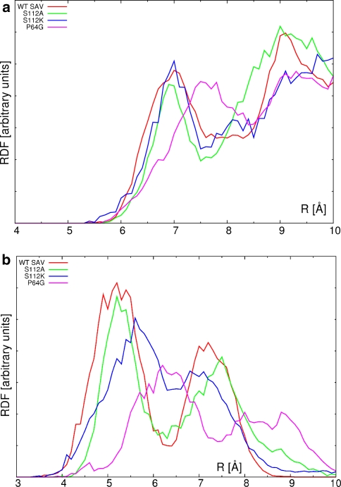
Finally, the consideration should be given to the cofactor–protein interactions. These are globally represented in the Fig. 9 as radial distribution functions (RDF) for two types of considered atom pairs. The first (upper) RDF graph represents distribution of the distances between metal centers and all of the backbone Cα atoms, while the second one describes contacts between the metal and all atoms of the closest residue 112. The S112A substitution in the tetrameric protein does not influence significantly the dynamics of the metal with respect to the backbone. This is reflected in the closest contact with the Cα atom—the value of ca. 7 Å for WT SAV is only slightly decreased in the cases of S112A and S112K mutants. However, comparison of Figs. 7 and 8 shows that the presence of the K112 residue conformationally stabilizes the cofactor. The local dynamics of the cofactor is most perturbed for the P64G variant, and the RDF maximum indicating the nearest metal—backbone carbon contact is moved away to 7.6 Å. The situation is similar when the nearest residue 112 (which is either Ser, Ala or Lys depending on the isoform) is considered as the basis for RDF calculations (Fig. 9, lower graph). Note that the relatively conservative S112A mutation does not change the RDF from the reference WT SAV values. On the other hand, the relatively large and more flexible lysine sidechain in S112K is responsible for the general broadening and shift of the RDF graph towards larger distances. The combined shift-and-broadening effect is even more pronounced for the P64G mutant, and this must be attributed again to changes in the local dynamics of the cofactor. This local dynamics is governed not only by the conformational flexibility, but also by the electrostatic potential (ESP) distribution around the cofactor, which will be described in section “Electrostatic potential maps”.
Fig. 9.
Unnormalized pair radial distribution function (in arbitrary units) for the Ru–Cα distances (upper graph) and Ru—residue 112 distances (lower graph)
Born–Oppenheimer molecular dynamics with ab initio force field—Comparison with classical force field hydrogen bonding network
The main object of this part of the study was investigation of the hydrogen bonding network—one of the factors responsible for the stable anchoring of the biotin in the binding pocket. The model assumed for this study (see Fig. 2) is taken from the wild-type SAV, since mutations of the pocket residues known in the literature decrease biotin-binding constant [29, 66], and contains the most important contacts, including unusual O–H···S hydrogen bond between Thr90 of streptavidin and the sulfur atom of biotin. O–H···S hydrogen bonds are less investigated compared to O–H···O or N–H···N interactions, however they are frequent in proteins [67] and can also be strong and important in some circumstances. Parameter-free techniques such as ab initio force field MD are well suited for the task of investigating such hydrogen bonds, which we have shown in our recent study on the properties of O–H···S bridge [68]. When constructing the model, we have omitted the rest of the protein, including the hydrophobic cage formed by tryptophan residues. As a consequence, the interactions are weakened and the stability of biotin position could be affected. Our aim was to estimate the importance of particular residues by observing if their close contacts with biotin are able to be sustained even in the absence of the protein scaffold.
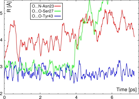
Figure 10 presents the time evolution of the three hydrogen-bonded contacts formed between the carbonyl oxygen atom (acceptor) of the biotin and the donating moieties: Asn23–NH, Ser27–OH and Tyr43–OH. It is visible that the only contact which is stable throughout the whole short simulation is Tyr43–OH···O(biotin). The other two contacts are not stable: Ser27–OH···O(biotin) dissociates after 4 ps of the simulations. However, the bridge between the biotin oxygen atom and Asn23–NH seems to be even weaker—it is very flexible from the start of the simulation, and the N–H moiety moves even farther away from the biotin ureido head throughout the MD run. This is consistent with the fact that generally N–H···O bonds are weaker than O–H···O contacts. The observed tendency is in agreement with classical force field findings showing very dynamic behavior of hydrogen bonds in the binding pocket [30].
Fig. 10.
Time evolution of the hydrogen bonds with carbonyl oxygen atom of biotin acting as an acceptor. Results of the DFT BOMD indicate that the O···N bond is the weakest of the contacts formed by the ureido oxygen atom
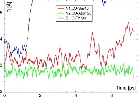
In the next step, contacts between ureido nitrogen atoms of biotin with surrounding residues were analyzed (see Fig. 11). These contacts also display diverse behavior: the N2–H(biotin)···O–Asp128 contact is preserved throughout the simulation, while N1–H(biotin)···O–Ser45 is more dynamic in nature—frequent bond breaking/formation takes place for this contact. The length of this bridge oscillates with even greater amplitude until at the end of the simulation. After 6 ps of elapsed time, the contact seems to become totally broken. This fact suggests again that some contacts are dynamically forming and breaking, but in the limited space of the binding pocket inside the protein, there is a very high chance of quick re-establishing of the hydrogen bond. Such events were frequently observed in classical simulations [30]. The behavior of the other contact, with participation of the negatively charged Asp128 residue, is very stable—this hydrogen bond is charge-assisted, which also strengthens the other contacts formed by the head of the biotin molecule [32].
Fig. 11.
Time evolution of the hydrogen bonds with ureido nitrogen atoms of biotin acting as donors, and the bond with sulfur atom acting as an acceptor. Results of DFT BOMD show that the hydrogen bond formed by sulfur atom is not stable
The two well-conserved contacts, Tyr43–OH···O(biotin) and N2–H(biotin)···O–Asp128, have the following averaged length during the ab initio runs: 2.794 ± 0.172 Å and 2.813 ± 0.118 Å. Table 2 reports also the corresponding data for the unstable bonds, calculated within their period of stability. Comparison of these values with experimental data (Table 2) shows that the ab initio force field MD, despite the simplified model, is able to describe the interactions within the system very well. The charge-assisted bridge to Asp128 is reproduced as slightly too strong, which can be attributed not only to the steric effects of the protein in the real system, but also to the moderating effect of the environment (protein and solvent) recognized macroscopically as the dielectric constant. The absence of this effect in the simplified ab initio model can lead to an increased role of electrostatic forces, and thus to the shortening of the charge-assisted bridge.
Table 2.
Distances of selected hydrogen bonds formed between the protein and biotin (btn) or the metal-loaded cofactor (L), in comparison to experimental X-ray data from the PDB database. Note the inequality of distances in two chains of the 2IZF PDB structure. The first column reports the DFT Born–Oppenheimer MD, the next five columns—classical force field MD simulations. Averages and standard deviations in Å. The values in bold typeface (DFT BOMD) denote the evaluations carried out only until the loss of stability of the considered bonds
| Contact | DFT BOMD | WT + btn | WT + L | P64G + L | S112A + L | S112K + L | 2IZF,B | 2IZF,D | 2QCB |
|---|---|---|---|---|---|---|---|---|---|
| Tyr43–OH···O | 2.794 ± 0.17 | 2.711 ± 0.13 | 2.735 ± 0.14 | 2.735 ± 0.13 | 2.735 ± 0.14 | 2.732 ± 0.14 | 2.770 | 2.639 | 2.707 |
| Asn23–NH···O | 4.266 ± 0.43 | 3.551 ± 0.46 | 3.455 ± 0.57 | 3.371 ± 0.38 | 3.333 ± 0.35 | 3.385 ± 0.38 | 3.033 | 2.904 | 2.980 |
| Ser27–OH···O | 2.982 ± 0.13 | 2.703 ± 0.14 | 2.761 ± 0.24 | 2.700 ± 0.12 | 2.694 ± 0.12 | 2.719 ± 0.15 | 2.698 | 2.564 | 2.674 |
| N1–H···O–Ser45 | 3.294 ± 0.25 | 3.073 ± 0.20 | 3.137 ± 0.22 | 3.130 ± 0.21 | 3.035 ± 0.17 | 3.145 ± 0.23 | 3.060 | 2.971 | 3.025 |
| N2–H···O–Asp128 | 2.813 ± 0.12 | 2.943 ± 0.16 | 2.934 ± 0.20 | 2.918 ± 0.16 | 2.908 ± 0.14 | 2.917 ± 0.17 | 2.881 | 2.872 | 2.857 |
| Thr90–OH···S | 3.676 ± 0.19 | 3.214 ± 0.17 | 3.414 ± 0.29 | 3.227 ± 0.19 | 3.199 ± 0.17 | 3.369 ± 0.27 | 3.316 | 3.325 | 3.365 |
The remaining contact formed between sulfur atom of the biotin and hydroxyl group of Thr90 is particularly unstable as it is broken already after 1.5 ps of ab initio run (see Fig. 11). This highlights its secondary role in securing the biotin in the binding pocket. Usually, only the network of hydrogen bonds formed by the ureido moiety of biotin is considered in the binding studies [32, 33]. Additionally, constrained classical force field MD of biotin in aqueous solution has shown that biotin is a flexible cofactor able to convert easily between several conformations (extended, semi-folded and folded states) [69]. This flexibility of biotin can also add to the ease with which the O–H···S bond was broken in our Born–Oppenheimer MD simulation. The discussion of these facts is supported by the analysis of the hydrogen bonding network in our classical force field MD (see Table 2 and Figures SI22–SI24 of the Online Resource 2). In agreement with previous calculations [30, 32, 33] this network is dynamical in nature, but the most important contacts are formed by the planar ureido moiety. However, classical force field simulations predict that the N1–H(biotin)···O–Ser45 and Thr90–O–H···S(biotin) bonds are stable, while the N2–H(biotin)···O–Asp128 contact is frequently disrupted. These facts indicate the role of the supporting protein scaffold, which helps the large-model AMBER simulations to predict long-term stability of some contacts. Indeed, length of our simulations (50 ns) is much larger than reorganization times for hydrogen bonding networks. Note that the contacts in the classical force field simulations (Figures SI22–SI24) seem to fall out of the hydrogen bonding range (for example reaching over 4 Å), but then return to the bonded values. This underlines the fact that the DFT BOMD small model and the AMBER large-system calculations provide complementary information on the studied systems.
Electrostatic potential maps
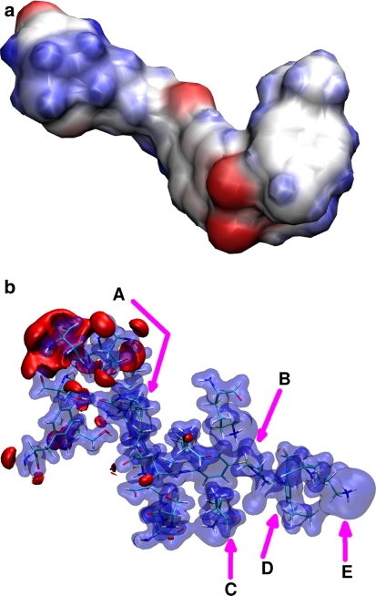
Two models—an isolated metal-bearing cofactor and the same cofactor inside the binding pocket of S112K SAV—were selected for generation of the electrostatic potential (ESP) maps (Fig. 12). In the case of the studied biotinylated piano-stool ruthenium catalyst (upper part of the Fig. 12), the metal center is not the source of the strongest electrostatic forces. The oxygen atoms of biotin, linker carbonyl and –SO2– group, followed by the ethylenediamine nitrogen atoms and biotin sulfur, seem to generate the strongest negative ESP. This means that positive residues, such as lysine, will interact preferentially with the –SO2– moiety providing additional anchor point, and thus some degree of stabilization of the cofactor structure. The result of such an interaction is visible on Figs. 7 and 8, which indicate how the S11K mutation is able to constrain the dynamics of the cofactor. Such statement is confirmed when the model of the cofactor-loaded binding pocket is analyzed (Fig. 12, lower part). Most interactions are located in the vicinity of the biotin moiety, but there are several other relevant contacts: between the –SO2– group of the cofactor and Lys112 of the second chain of the protein, and between the metal center and Lys112 or Lys121 from the primary chain forming the binding pocket. These residues were experimentally found to afford modification of the yield and enantioselectivity of the catalytic process of transfer hydrogenation carried out by the artificial metalloenzyme, and the ESP maps provide additional proof that the formed contacts affect directly either the metal center or the groups responsible for the conformational freedom of the cofactor.
Fig. 12.
Electrostatic potential distribution around the [η6-(p-cymene)Ru(Biot-p-L)Cl] cofactor (upper graph) and in the model of the cofactor binding pocket of the S112K SAV (lower graph). Two rings of the biotin moiety (a) are located in an interaction-rich pocket. The SO2 fragment (b) is in contact with Lys112 residue (c). The metal center (d) lies close to Lys121 (e). Isocontours at +0.25 a.u. (blue) and −0.075 a.u. (red). Results of DFT B3LYP/SDD calculations
Conclusions
The simulations carried out in this study were devised to test two related phenomena: (i) The influence of selected point mutations on the structure and dynamics of the protein as well as cofactors, and (ii) The stability of the hydrogen bonding network which is one of the factors responsible for the binding of biotin and biotinylated cofactors. Our findings can be summarized as follows:
The point mutations did not influence the overall structure of the protein, in agreement with the experimental data [36], and the local dynamics of the backbone seems to be also almost not changed irrespective of the mutation.
The absence of cofactors generally leads to increased structural fluctuations (WT SAV and the P64G mutant are exceptions), which underlines the fact that biotin-(strept)avidin systems are fine-tuned examples of complementarity of the host-cofactor interactions.
The cofactors easily change their conformation, but are also able to reside in a given conformational minimum for an extended period of time, as shown in Figures SI16–SI19;
The local environment of the ruthenium is influenced by the mutations, and surprisingly the effect is most pronounced for the P64G mutation which does not take place in the immediate vicinity of the metal, but can indirectly affect the L7,8 loop of streptavidin (residues 112–122).
The network of hydrogen bonds formed between biotin and surrounding streptavidin residues is very dynamic in nature and frequent bond formation/breaking takes place. The most persistent contact is Tyr43–OH···O(biotin). This fact is visible in the long-time-scale classical force field simulation, as well as in the small model short ab initio Born–Oppenheimer MD run.
The simulation protocols for molecular dynamics studies of biotin-streptavidin systems with classical and ab initio force fields were tested successfully and rationalized the dynamics of the cofactor.
A very important finding is associated with P64G mutant. The mutated site is located in the flexible part of the protein. Its effect on the catalytic activity is, however, caused not only by the flexibility introduced possibly into the backbone. Additional cause is also the presence of terminal parts of the cofactors in the vicinity of the residue 64.
Electronic supplementary material
Below is the link to the electronic supplementary material.
Acknowledgments
This work was supported by the European Union as the FP6 Marie Curie research training Network IBAAC Project, MRTN-CT-2003-505020, and by the Slovenian Ministry of Higher Education, Science and Technology research grant P1-017. J.J.P. and A.J.-M. gratefully acknowledge the Wrocław Center for Networking and Supercomputing (WCSS), the Academic Computer Center CYFRONET-KRAKÓW (Grants KBN/SGI/UWrocl/029/1998 KBN/SGI/UWrocl/078/2001), the Poznań Supercomputing and the Networking Center and the Academic Computer Center in Gdańsk (TASK) for providing computer time and facilities.
Open Access
This article is distributed under the terms of the Creative Commons Attribution Noncommercial License which permits any noncommercial use, distribution, and reproduction in any medium, provided the original author(s) and source are credited.
References
- 1.Trindade AF, Gois PMP, Afonso CAM. Chem Rev. 2009;109:418–514. doi: 10.1021/cr800200t. [DOI] [PubMed] [Google Scholar]
- 2.Krämer R. Angew Chem Int Ed. 2006;45:858–860. doi: 10.1002/anie.200502907. [DOI] [PubMed] [Google Scholar]
- 3.Gennari C, Piarulli U. Chem Rev. 2003;103:3071–3100. doi: 10.1021/cr020058r. [DOI] [PubMed] [Google Scholar]
- 4.Jäkel C, Paciello R. Chem Rev. 2006;106:2912–2942. doi: 10.1021/cr040675a. [DOI] [PubMed] [Google Scholar]
- 5.Zhang TY. Chem Rev. 2006;106:2583–2595. doi: 10.1021/cr040677v. [DOI] [PubMed] [Google Scholar]
- 6.Wilson ME, Whitesides GM. J Am Chem Soc. 1978;100:306–307. doi: 10.1021/ja00469a064. [DOI] [Google Scholar]
- 7.Yeung N, Lin YW, Gao YG, Zhao X, Russell BS, Lei L, Miner KD, Robinson H, Lu Y. Nature. 2009;462:1079–1082. doi: 10.1038/nature08620. [DOI] [PMC free article] [PubMed] [Google Scholar]
- 8.Boersma AJ, Klijn JE, Feringa BL, Roelfes G. J Am Chem Soc. 2008;130:11783–11790. doi: 10.1021/ja803170m. [DOI] [PubMed] [Google Scholar]
- 9.Coquière D, Bos J, Beld J, Roelfes G. Angew Chem Int Ed. 2009;48:5159–5162. doi: 10.1002/anie.200901134. [DOI] [PubMed] [Google Scholar]
- 10.Hwang HJ, Carey JR, Brower ET, Gengenbach AJ, Abramite JA, Lu Y. J Am Chem Soc. 2005;127:15356–15357. doi: 10.1021/ja054983h. [DOI] [PubMed] [Google Scholar]
- 11.Lin CC, Lin CW, Chan ASC. Tetrahedron Asymmetr. 1999;10:1887–1893. doi: 10.1016/S0957-4166(99)00193-7. [DOI] [Google Scholar]
- 12.Okrasa K, Kazlauskas RJ. Chem Eur J. 2006;12:1587–1596. doi: 10.1002/chem.200501413. [DOI] [PubMed] [Google Scholar]
- 13.Reetz MT, Jiao N. Angew Chem Int Ed. 2006;45:2416–2419. doi: 10.1002/anie.200504561. [DOI] [PubMed] [Google Scholar]
- 14.Pordea A, Creus M, Panek JJ, Duboc C, Mathis D, Novič M, Ward TR. J Am Chem Soc. 2008;130:8085–8088. doi: 10.1021/ja8017219. [DOI] [PubMed] [Google Scholar]
- 15.Chin J. Acc Chem Res. 1991;24:145–152. doi: 10.1021/ar00005a004. [DOI] [Google Scholar]
- 16.Fitzsimons MP, Barton JK. J Am Chem Soc. 1997;119:3379–3380. doi: 10.1021/ja9633981. [DOI] [Google Scholar]
- 17.Suh J. Acc Chem Res. 2003;36:562–570. doi: 10.1021/ar020037j. [DOI] [PubMed] [Google Scholar]
- 18.Yoo CE, Chae PS, Kim JE, Jeong EJ, Suh J. J Am Chem Soc. 2003;125:14580–14589. doi: 10.1021/ja034730t. [DOI] [PubMed] [Google Scholar]
- 19.Skander M, Humbert N, Collot J, Gradinaru J, Klein G, Loosli A, Sauser J, Zocchi A, Gilardoni F, Ward TR. J Am Chem Soc. 2004;126:14411–14418. doi: 10.1021/ja0476718. [DOI] [PubMed] [Google Scholar]
- 20.Kruppa M, König B. Chem Rev. 2006;106:3520–3560. doi: 10.1021/cr010206y. [DOI] [PubMed] [Google Scholar]
- 21.Letondor C, Pordea A, Humbert N, Ivanova A, Mazurek S, Novič M, Ward TR. J Am Chem Soc. 2006;128:8320–8328. doi: 10.1021/ja061580o. [DOI] [PubMed] [Google Scholar]
- 22.De M, You C, Srivastava S, Rotello VM. J Am Chem Soc. 2007;129:10747–10753. doi: 10.1021/ja071642q. [DOI] [PubMed] [Google Scholar]
- 23.Wilchek M, Bayer EA. Methods Enzymol. 1990;184:5–13. doi: 10.1016/0076-6879(90)84256-G. [DOI] [PubMed] [Google Scholar]
- 24.Green NM. Adv Protein Chem. 1975;29:85–133. doi: 10.1016/S0065-3233(08)60411-8. [DOI] [PubMed] [Google Scholar]
- 25.Weber PC, Wendoloski JJ, Pantoliano MW, Salemme FR. J Am Chem Soc. 1992;114:3197–3200. doi: 10.1021/ja00035a004. [DOI] [Google Scholar]
- 26.Savage D. Avidin-Biotin Chemistry: a handbook. Rockford: Pierce Chemical Co; 1993. [Google Scholar]
- 27.Soller T, Ringler M, Wunderlich M, Klar TA, Feldmann J, Josel HP, Koci J, Markert Y, Nichtl A, Kürzinger K. J Phys Chem B. 2008;112:12824–12826. doi: 10.1021/jp8044065. [DOI] [PubMed] [Google Scholar]
- 28.Miyamoto S, Kollman PA. Proc Natl Acad Sci USA. 1993;90:8402–8406. doi: 10.1073/pnas.90.18.8402. [DOI] [PMC free article] [PubMed] [Google Scholar]
- 29.Chilkoti A, Tan PH, Stayton PS. Proc Natl Acad Sci USA. 1995;92:1754–1758. doi: 10.1073/pnas.92.5.1754. [DOI] [PMC free article] [PubMed] [Google Scholar]
- 30.Panek JJ, Ward TR, Jezierska A, Novič M. J Mol Model. 2009;15:257–266. doi: 10.1007/s00894-008-0382-0. [DOI] [PubMed] [Google Scholar]
- 31.Lazaridis T, Masunov A, Gandolfo F. Proteins Struct Funct Gen. 2002;47:194–208. doi: 10.1002/prot.10086. [DOI] [PubMed] [Google Scholar]
- 32.DeChancie J, Houk KN. J Am Chem Soc. 2007;129:5419–5429. doi: 10.1021/ja066950n. [DOI] [PMC free article] [PubMed] [Google Scholar]
- 33.Lei Y, Li H, Zhang R, Han S. J Phys Chem B. 2007;111:14370–14377. doi: 10.1021/jp076914q. [DOI] [PubMed] [Google Scholar]
- 34.Noyori R, Hashiguchi S. Acc Chem Res. 1997;30:97–102. doi: 10.1021/ar9502341. [DOI] [Google Scholar]
- 35.Letondor C, Humbert N, Ward TR. Proc Natl Acad Sci USA. 2005;102:4683–4687. doi: 10.1073/pnas.0409684102. [DOI] [PMC free article] [PubMed] [Google Scholar]
- 36.Creus M, Pordea A, Rossel T, Sardo A, Letondor C, Ivanova A, LeTrong I, Stenkamp RE, Ward TR. Angew Chem Int Ed. 2008;47:1400–1404. doi: 10.1002/anie.200704865. [DOI] [PubMed] [Google Scholar]
- 37.Katz BA. J Mol Biol. 1997;274:776–800. doi: 10.1006/jmbi.1997.1444. [DOI] [PubMed] [Google Scholar]
- 38.Hohenberg P, Kohn W. Phys Rev. 1964;136:B864–B871. doi: 10.1103/PhysRev.136.B864. [DOI] [Google Scholar]
- 39.Kohn W, Sham LJ. Phys Rev. 1965;140:A1133–A1138. doi: 10.1103/PhysRev.140.A1133. [DOI] [Google Scholar]
- 40.Becke AD. J Chem Phys. 1993;98:5648–5652. doi: 10.1063/1.464913. [DOI] [Google Scholar]
- 41.Lee C, Yang W, Parr RG. Phys Rev B. 1988;37:785–789. doi: 10.1103/PhysRevB.37.785. [DOI] [PubMed] [Google Scholar]
- 42.Andrae D, Häussermann U, Dolg M, Stoll H, Preuss H. Theor Chim Acta. 1990;77:123–141. doi: 10.1007/BF01114537. [DOI] [Google Scholar]
- 43.Besler BH, Merz KM, Jr, Kollman PA. J Comp Chem. 1990;11:431–439. doi: 10.1002/jcc.540110404. [DOI] [Google Scholar]
- 44.Frisch MJ, Trucks GW, Schlegel HB, Scuseria GE, Robb MA, Cheeseman JR, Montgomery JA, Jr, Vreven T, Kudin KN, Burant JC, Millam JM, Iyengar SS, Tomasi J, Barone V, Mennucci B, Cossi M, Scalmani G, Rega N, Petersson GA, Nakatsuji H, Hada M, Ehara M, Toyota K, Fukuda R, Hasegawa J, Ishida M, Nakajima T, Honda Y, Kitao O, Nakai H, Klene M, Li X, Knox JE, Hratchian HP, Cross JB, Bakken V, Adamo C, Jaramillo J, Gomperts R, Stratmann RE, Yazyev O, Austin AJ, Cammi R, Pomelli C, Ochterski JW, Ayala PY, Morokuma K, Voth GA, Salvador P, Dannenberg JJ, Zakrzewski VG, Dapprich S, Daniels AD, Strain MC, Farkas O, Malick DK, Rabuck AD, Raghavachari K, Foresman JB, Ortiz JV, Cui Q, Baboul AG, Clifford S, Cioslowski J, Stefanov BB, Liu G, Liashenko A, Piskorz P, Komaromi I, Martin RL, Fox DJ, Keith T, Al-Laham MA, Peng CY, Nanayakkara A, Challacombe M, Gill PMW, Johnson B, Chen W, Wong MW, Gonzalez C, Pople JA. Gaussian 03, revision C.02. Wallingford: Gaussian Inc.; 2004. [Google Scholar]
- 45.Hornak V, Abel R, Okur A, Strockbine B, Roitberg A, Simmerling C. Proteins Struct Funct Bioinf. 2006;65:712–725. doi: 10.1002/prot.21123. [DOI] [PMC free article] [PubMed] [Google Scholar]
- 46.Jorgensen WL, Chandrasekhar J, Madura JD, Impey RW, Klein ML. J Chem Phys. 1983;79:926–935. doi: 10.1063/1.445869. [DOI] [Google Scholar]
- 47.Darden T, York D, Pedersen LG. J Chem Phys. 1993;98:10089–10092. doi: 10.1063/1.464397. [DOI] [Google Scholar]
- 48.Essman U, Perela L, Berkowitz ML, Darden T, Lee H, Pedersen LG. J Chem Phys. 1995;103:8577–8592. doi: 10.1063/1.470117. [DOI] [Google Scholar]
- 49.Sagui C, Darden T. Annu Rev Biophys Biomol Struct. 1999;28:155–179. doi: 10.1146/annurev.biophys.28.1.155. [DOI] [PubMed] [Google Scholar]
- 50.Case DA, Darden TA, Cheatham TE, III, Simmerling CL, Wang J, Duke RE, Luo R, Merz KM, Pearlman DA, Crowley M, Walker RC, Zhang W, Wang B, Hayik S, Roitberg A, Seabra G, Wong KF, Paesani F, Wu X, Brozell S, Tsui V, Gohlke H, Yang L, Tan C, Mongan J, Hornak V, Cui G, Beroza P, Mathews DH, Schafmeister C, Ross WS, Kollman PA. AMBER 9. San Francisco: University of California; 2006. [Google Scholar]
- 51.Adelman SA, Doll JD. J Chem Phys. 1976;64:2375–2388. doi: 10.1063/1.432526. [DOI] [Google Scholar]
- 52.Feller SE, Zhang Y, Pastor RW, Brooks BR. J Chem Phys. 1995;103:4613–4621. doi: 10.1063/1.470648. [DOI] [Google Scholar]
- 53.Ryckaert JP, Ciccotti G, Berendsen HJC. J Comp Phys. 1977;23:327–341. doi: 10.1016/0021-9991(77)90098-5. [DOI] [Google Scholar]
- 54.Humphrey W, Dalke A, Schulten K. J Molec Graph. 1996;14:33–38. doi: 10.1016/0263-7855(96)00018-5. [DOI] [PubMed] [Google Scholar]
- 55.VandeVondele J, Krack M, Mohamed F, Parrinello M, Chassaing T, Hutter J. Comput Phys Comm. 2005;167:103–128. doi: 10.1016/j.cpc.2004.12.014. [DOI] [Google Scholar]
- 56.Lippert G, Hutter J, Parrinello M. Mol Phys. 1997;92:477–487. doi: 10.1080/00268979709482119. [DOI] [Google Scholar]
- 57.CP2 K version 2.0.0 (Development Version), the CP2 K developers group (2008) CP2 K is freely available from http://cp2k.berlios.de/
- 58.Goedecker S, Teter M, Hutter J. Phys Rev B. 1996;54:1703–1710. doi: 10.1103/PhysRevB.54.1703. [DOI] [PubMed] [Google Scholar]
- 59.Hartwigsen J, Goedecker S, Hutter J. Phys Rev B. 1998;58:3641–3662. doi: 10.1103/PhysRevB.58.3641. [DOI] [Google Scholar]
- 60.Krack M. Theor Chem Acc. 2005;114:145–152. doi: 10.1007/s00214-005-0655-y. [DOI] [Google Scholar]
- 61.Becke AD. Phys Rev A. 1988;38:3098–3100. doi: 10.1103/PhysRevA.38.3098. [DOI] [PubMed] [Google Scholar]
- 62.Nosé S. Mol Phys. 1984;52:255–268. doi: 10.1080/00268978400101201. [DOI] [Google Scholar]
- 63.Nosé S. J Chem Phys. 1984;81:511–519. doi: 10.1063/1.447334. [DOI] [Google Scholar]
- 64.Williams T, Kelley C. Gnuplot 4.0. Copyright © 1986–1993, 1998, 2004
- 65.Izrailev S, Stepaniants S, Balsera M, Oono Y, Schulten K. Biophys J. 1997;72:1568–1581. doi: 10.1016/S0006-3495(97)78804-0. [DOI] [PMC free article] [PubMed] [Google Scholar]
- 66.Hyre DE, Le Trong I, Freitag S, Stenkamp RE, Stayton PS. Protein Sci. 2000;9:878–885. doi: 10.1110/ps.9.5.878. [DOI] [PMC free article] [PubMed] [Google Scholar]
- 67.Gregoret LM, Rader SD, Fletterick RJ, Cohen FE. Proteins Struct Funct Gen. 1991;9:99–107. doi: 10.1002/prot.340090204. [DOI] [PubMed] [Google Scholar]
- 68.Jezierska A, Panek JJ. J Comp Chem. 2009;30:1241–1250. doi: 10.1002/jcc.21158. [DOI] [PubMed] [Google Scholar]
- 69.Lei Y, Li H, Zhang R, Han S. J Phys Chem B. 2004;108:10131–10137. doi: 10.1021/jp049207v. [DOI] [PubMed] [Google Scholar]
Associated Data
This section collects any data citations, data availability statements, or supplementary materials included in this article.


