Abstract
Organically modified silica coatings were prepared on metal nanowires using a variety of silicon alkoxides with different functional groups (i.e., carboxyl groups, polyethylene oxide, cyano, dihydroimidazole, and hexyl linkers). Organically modified silicas were deposited onto the surface of 6-μm-long, ∼300-nm-wide, cylindrical metal nanowires in suspension by the hydrolysis and polycondensation of silicon alkoxides. Syntheses were performed at several ratios of tetraethoxysilane to an organically modified silicon alkoxide to incorporate desired functional groups into thin organosilica shells on the nanowires. These coatings were characterized using transmission electron microscopy, X-ray photoelectron spectroscopy, and infrared spectroscopy. All of the organically modified silicas prepared here were sufficiently porous to allow the removal of the metal nanowire cores by acid etching to form organically modified silica nanotubes. Additional functionality provided to the modified silicas as compared to unmodified silica prepared using only tetraethoxysilane precursors was demonstrated by chromate adsorption on imidazole-containing silicas and resistance to protein adsorption on polyethyleneoxide-containing silicas. Organically modified silica coatings on nanowires and other nano- and microparticles have potential application in fields such as biosensing or nanoscale therapeutics due to the enhanced properties of the silica coatings, for example, the prevention of biofouling.
Introduction
Modified silicon alkoxide precursors have been used to control the chemical functionality and structure of bulk ORMOSIL (organically modified silanes) materials.1−6 ORMOSILs are inorganic−organic hybrid materials, such as RSi(OCH3)3; where the organic moiety, R, is covalently bound to the resulting matrix upon reaction.(2) This prevents loss of the organic functionalities due to leaching.(1) The choice of precursor molecule(s) affects the porosity, chemical reactivity, structure, morphology, hydrophobicity, and materials properties of the resultant sol−gel, e.g., enabling the encapsulation of proteins, dyes, nanoparticles, or catalysts within the matrix.2−4 Mackenzie and Bescher described how using silicon alkoxide precursors modified with methyls, vinyls, polydimethylsiloxanes, or carbazoles resulted in materials that were hydrophobic, able to cross-link with acrylic groups, were rubbery, or demonstrated charge transport properties, respectively, compared to sol−gels prepared from TEOS or tetramethoxysilanes (TMOS).(5) Silicon alkoxide sol−gel precursors with, e.g., anthracene, bridging units that fluoresce when excited with ultraviolet light have produced materials with the fluorescent molecule covalently attached to the structure, unable to leach away.(7) Monolithic ORMOSILs have also been synthesized with N-(3-triethoxysilylpropyl)-4,5-dihydroimidazole (NTPDI) as a sol−gel precursor to introduce a dihydroimidazole functionality into the bulk material for chelating metal ions.8,9 These advanced materials have proven useful in a variety of applications: adsorbent materials, (bio)chemical sensors, nonlinear optical materials, and coatings.2,6 In addition to monolithic ORMOSILs, these materials have been prepared as thin films to protect metallic or polymeric surfaces or to provide functionality for sensing or electrical applications.10−12 Micro- and nanoparticulate organically modified silicas have also been prepared, for applications including biosensors and in vivo imaging.(13) To the best of our knowledge, ORMOSILs have not previously been reported as coatings for nanowires, nor have they been formed into hollow tubes.
Metallic nanowires are attractive for applications ranging from multiplexed biosensing14−18 and electronics19,20 to catalytically driven nanomotors.(21) For most applications, it is desirable to control the nanowire surface chemistry. Previous methods of modifying the surface properties of metallic nanowires have included direct adsorption of organic molecules onto the metallic surface,22,23 attachment of DNA through thiol—Au linkages(16) or proteins by first functionalizing the nanowire with an organic moiety,14,24 formation of a silica sheath into which nanowires were grown,(25) or a modified sol−gel approach in solution.26−28 Alkilany et al. prepared gold nanowires in solution with a bilayer of cetyltrimethylammonium bromide (CTAB) to act as a hydrophobic layer to bind organic molecules in aqueous solution.(22) Silica is an attractive coating for nanoparticles, because it protects the particle core from oxidation and from molecules in solution, prevents undesired adsorption of molecules onto the metal surface, acts as structural support, stabilizes particles for transfer to different solvents, and provides covalent attachment points for biomolecules through well-understood chemistry.17,27,29,30 Nanowires have been coated with SiO2 in a variety of ways: (1) forming the silica shell first by depositing SiCl4 into alumina pores and subsequently electrochemically filling the pores with the metal of choice,(25) (2) high-temperature reactions,(31) (3) growth of sodium silicate on the surface of the nanowires in suspension,32,33 or (4) reaction of a silicon alkoxide, such as tetraethoxysilane (TEOS) in solution.26−28 Stabilizing agents, such as 3-mercaptopropyltrimethoxysilane, may be used to make surfaces more vitreophilic,(32) but are not always necessary for silica growth.(27)
Removal of the metallic cores after deposition of a SiO2 shell is one route to preparing silica nanotubes, which are attractive in bioanalysis, catalysis, and drug delivery, and are particularly desired due to the hydrophilicity of silica, the ability to functionalize the surface with well-known silane chemistry and an inner void that can be filled.34,35 SiO2 nanotubes have also been prepared through a multistep fabrication approach using thermal oxidation of silicon nanowire arrays to form silica tube arrays.(34) Additionally, templated synthesis of inorganic silica nanotubes(36) has been accomplished via negative templating within the pores of alumina35,37 or positive templating using biological,(38) carbon nanotube,(39) or nanowire templates.26,32,40 ORMOSIL tubes could offer additional functionality as compared to these inorganic structures.
Literature on silica coatings for nanoparticles generally, and for nanospheres in particular, is more extensive than for nanowires. The procedures to coat nanoparticles with silica have been well-investigated; a variety of different processes have resulted in uniform, well-controlled coatings on particle surfaces with applications in catalysis, diagnostics, SERS, and photothermal therapy.(41) Spherical metal nanoparticles (e.g., Au, Ag, Pt) have been coated with SiO2 through the hydrolysis and polycondensation of TEOS on the particle surface42,43 or by pretreatment of the particles with 3-aminopropyltrimethoxysilane and then sodium silicate so the particles can be transferred into ethanol without aggregating.(44) Alternately, poly(vinylpyrrolidone) has been adsorbed to the surface of the colloidal particles to prevent aggregation upon transfer of the particles into ethanol for the growth of silica through the Stöber process.(45) Although SiO2 surfaces offer many advantages, it is desirable to tailor surface properties for more advanced applications without an additional functionalization step. Synthesizing hybrid silica coatings using organically modified silicon alkoxide precursors would retain the advantages of SiO2, while enabling control of the surface chemistry via incorporation of different functional groups. Surprisingly, although some reports of more complex, hybrid coatings have appeared,(46) the vast majority of silica coatings on nano- and microparticles have been simple inorganic silicas.
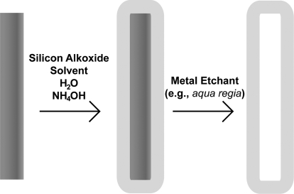
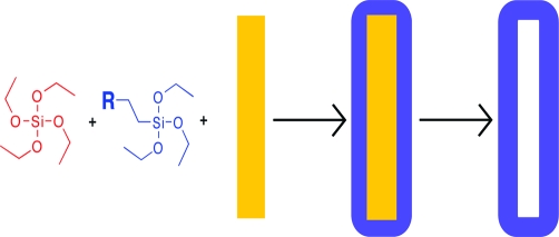
Here, we present the fabrication and characterization of silica coatings incorporating a variety of functional groups onto metal nanowires in suspension. ORMOSIL films on the nanowires were prepared using a modified sol−gel synthesis in which functional group containing silicon alkoxide precursor molecules and TEOS were co-deposited (Scheme 1). Nanotubes of the various modified silicas were produced by acid dissolution of the nanowire scaffolds (Scheme 1). The presence of the functional groups in the ORMOSIL shells was confirmed through infrared spectroscopy (FT-IR) and proof-of-concept binding experiments. To our knowledge, this is the first example of ORMOSIL coatings on nanowires or nanoparticles of any kind. Such coatings may prove valuable in a wide range of biomedical and materials applications.
Scheme 1. Fabrication Process for Silica Coating Nanowires and the Subsequent Dissolution of the Nanowire Scaffold to Produce Hollow Silica Nanotubes.
Experimental Materials and Methods
Materials
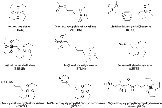
Tetraethoxysilane, 98% (TEOS), 3-acryloxypropyltrimethoxysilane (AcPTMS), bis(trimethoxysilylethyl)benzene (BTEB), bis(triethoxysilyl)ethylene (BTESE), 1,6-bis(trimethoxysilyl)hexane (BTMH), 2-cyanoethyltriethoxysilane (CETES), (3-isocyanatopropyl)triethoxysilane (ICPTES), N-(3-triethoxysilylpropyl)-4,5-dihydroimidazole (NTPDI), and N-(triethoxysilylpropyl)-o-polyethylene oxide urethane (PEO) were obtained from Gelest, Inc. 3-Aminopropyltrimethoxysilane (APTMS) was acquired from TCI America. Spectrograde KCl was obtained from International Crystal Laboratories. Lactate dehydrogenase from porcine heart was purchased from Calbiochem. Alexa Fluor 555 protein labeling kit and Alexa Fluor 488 goat antimouse IgG (H+L) were purchased from Invitrogen. DNA sequences were purchased form Integrated DNA Technologies. Sulfosuccinimidyl-4-(N-maleimidomethyl)cyclohexane-1-carboxylate (Sulfo-SMCC) was purchased from Pierce Protein Research Products, Thermo Scientific. All water used was 18.2 MΩ-cm Nanopure water from a Barnstead system. All reagents were used as purchased without further purification; the silanes were aliquoted out in a glovebox under nitrogen gas to prevent hydrolysis from water vapor in the air.
Nanowire Synthesis
Metallic nanowires were synthesized by galvanostatic electrodeposition into anodized aluminum oxide Anodisc 25 membranes with 0.2 μm pores (I = 1.65 mA) on an in-house system, as has been described previously.14,47 Silver (300 nm) was vapor deposited on one side of the membranes to act as the working electrode. Nanowires were electrodeposited in the pores of the membrane, after which the silver backing was dissolved in 33% v/v nitric acid. Nanowires were then released into suspension by vortexing the membrane in 3 M NaOH and rinsed with 3 M NaOH, followed by DI H2O and three times with ethanol (EtOH) before suspension in 1 mL EtOH. One batch of nanowires produced ∼109 nanowires.(15)
While most of the work in this manuscript was performed with 6 μm Au nanowires, nanowires composed of segments of both Au and a sacrificial metal (Ag or Ni) were used to facilitate rapid screening of reaction conditions using light microscopy. For example, if a Au−Ag−Au wire was coated with silica and the Ag segment was subsequently removed by acid etching, the two Au ends would remain associated. If the silica coating was unsuccessful, the two Au ends would not remain associated. Once viable reaction conditions were identified, further work was conducted with Au wires, with silica imaging via TEM.
Silica Coating of Nanowires
Nanowires were coated with TEOS silica as described in the literature26,27 (Scheme 1); this procedure was then adjusted to produce different glass chemistries by adding the silicon alkoxide of choice to the reaction mixture at the same time as the TEOS; however, acetonitrile (ACN) was used as the solvent, rather than EtOH. Briefly, 300 μL nanowires (batch concentration) were combined with 490 μL EtOH, 160 μL DI H2O, 40 μL TEOS, and 10 μL NH4OH (14.8 M) in a microcentrifuge tube. After one hour of sonication in a Crest Ultrasonicator with a Genesis module operating in the frequency range 39−41 kHz at 190−200 W, the coated nanowires were rinsed three times with ∼1 mL EtOH by centrifugation (2000 g). Specific reaction conditions to produce the modified silica coatings can be found in Table 1.
Table 1. Reaction Parameters and TEM and IR Analysis of Silica-Coated, 6 μm Gold Nanowires.
| sample | ratio of TEOS to modified silane (%)a | reaction volumes | number of coatings | reaction time/coating (min) | thickness on nanowireb (nm) | observed characteristic IR peaks (cm-1)(57) |
|---|---|---|---|---|---|---|
| TEOS | n/a | 40.0 μL TEOS | 1 | 60 | 50.8 ± 2.6 | 2985, 2944, 2933, 2906 (C−H); 1300−996 (Si−O—Si) |
| TEOS:AcPTES | 75:25 | 29.9 μL TEOS, 13.2 μL AcPTES | 3 | 60 | 6.00 ± 1.1 | 2925, 2954 (C−H); 1726 (C=O); 1334−947 (Si−O—Si) |
| TEOS:BTEB | 91:9 | 36.4 μL TEOS, 3.77 μL BTEB | 3 | 60 | 43.1 ± 4.8 | 2982, 2945 (C−H); 1314−980 (Si−O—Si) |
| TEOS:BTESE | 75:25 | 29.9 μL TEOS, 11.0 μL BTESE | 3 | 60 | 20.2 ± 3.4 | 2976, 2932 (C−H); 1284−982 (Si−O—Si) |
| TEOS:BTMH | 67:33 | 26.6 μL TEOS, 12.8 μL BTMH | 1 | 60 | 15.2 ± 1.4 | 2932, 2864 (C−H); 1325−990 (Si−O—Si) |
| TEOS:CETES | 75:25 | 29.9 μL TEOS, 13.2 μL CETES | 3 | 60 | 8.7 ± 2.6 | 2930, 2853, 2809 (C−H); 2253 (C≡N); 1284−955 (Si−O—Si) |
| TEOS:ICPTES | 80:20 | 31.8 μL TEOS, 11.9 μL ICPTES | 3 | 10 | 8.3 ± 2.3 | 2980, 2949, 2887, 2836 (C−H); 1653 (N−C=O, amide); 1309−978 (Si−O—Si) |
| TEOS:NTPDI | 25:75 | 6.65 μLTEOS, 21.7 μL NTPDI | 4 | 10 | 24.7 ± 3.8 | |
| 50:50 | 9.98 μL TEOS, 16.3 μL NTPDI | 4 | 10 | 24.5 ± 4.7 | 2930, 2888 (C−H); 1651 (C=N); 1601 (C−N); 1284−897 (Si−O—Si) | |
| 75:25 | 15.0 μL TEOS, 8.13 μL NTPDI | 4 | 10 | 17.5 ± 2.3 | ||
| 83:17 | 16.7 μL TEOS, 5.43 μL NTPDI | 4 | 10 | 18.5 ± 1.9 | ||
| 91:9 | 18.2 μL TEOS, 2.96 μL NTPDI | 4 | 10 | 12.7 ± 2.2 | ||
| TEOS:PEO | 75:25 | 30.0 μL TEOS, 24.7 μL PEO | 3c | 60 | 16.3 ± 1.8 | 2928, 2877 (C−H); 1692 (amide I); 1530 (amide II); 1331−982 (Si−O—Si) |
Ratio of the number of reactive groups of TEOS to the number of reactive groups of the modified silicon alkoxide.
n = 100 measurements made.
Nanowires coated 5 times at 60 min each to make nanotubes with thick enough walls to prevent collapse during drying or under the vacuum of the TEM; IR and TEM analysis done using nanowires coated 3 times.
Silica nanotubes were prepared by first silica coating metallic nanowires with the desired number of coatings for the specific silicon alkoxides used (Table 1, Scheme 1). The coated nanowires were then rinsed into water, spun down, and suspended in 400 μL aqua regia for >1 h.(48) The nanotubes were rinsed 2× with water and 3× with EtOH before suspension in EtOH for TEM and IR analyses. None of the coated nanowire or silica nanotube samples were dried until directly prior to TEM or IR analysis.
Materials Characterization
Transmission electron microscopy images were obtained using a JEOL TEM 1200 EXII instrument with a high-resolution Tietz F224 digital camera at an accelerating voltage of 80 kV. Analysis of the TEM images was done using Image J software to determine glass thickness by averaging over many nanowires and measurements (n = 100) (Image J software is available for free at www.NIH.gov).
FT-IR spectra were acquired on a Bruker IFS 66/s spectrometer using a Collector II diffuse reflection accessory equipped with a high-temperature/vacuum (HTV) sample chamber.(49) The HTV chamber was employed to reproducibly reduce moisture content and minimize spectral interferences in the water O−H stretching (∼3400 cm−1) and O−H deformation (∼1640 cm−1) regions. Silica-coated nanowires (40 μL TEOS-coated nanowires in ethanol, or 200 μL of the modified silica coated nanowires, due to differences in coating thickness, at batch concentration in ethanol) were dispensed into a mortar where residual solvent was evaporated using a heat gun. Nanowires were then ground for 120 s with a pestle in the presence of 60 mg KCl to minimize differences in particle size to keep the scattering coefficient constant.(50) Samples were loaded into the HTV and heated to 75 °C for 5 min prior to spectral acquisition to facilitate drying. Preliminary measurements where samples were dried at higher temperatures (115 and 150 °C) reveal changes in the spectra of the nanowire coating beyond simple removal of molecular water. Progressed polycondensation of tetraethoxysilane has been observed in the bulk with increasing temperature as water is driven off.(51) All spectra were acquired by averaging 400 scans at 6 cm−1 and were referenced to the spectrum of KCl powder prepared in an analogous manner. Spectral acquisition and processing was done with OPUS 6.0 software. All spectra were plotted in absorbance units, thus avoiding baseline offset errors of the Kubelka−Munk transformation.(52) Vapor-phase water features were subtracted from the spectra using the OPUS atmospheric compensation function. The CO2 mode centered at ∼2350 cm−1 was mathematically removed, a one point baseline offset was applied at ∼3900 cm−1, and the Si−O−Si peak centered at ∼1150 cm−1 was normalized to an absorbance value of one to improve visualization. IR analysis of the silica nanotubes was done in an identical fashion.
X-ray photoelectron spectroscopy (XPS) data was obtained on a Kratos Analytical Axis Ultra with a monochromatic Al Kα X-ray source operating at an X-ray power of 240 W. Spectra were collected at a 90° photoelectron takeoff angle with respect to the sample plane with a pass energy of 20 eV and an energy step of 0.1 eV. All spectra were taken with the charge neutralizer on and referenced to the C 1s at 285.0 eV. The samples were analyzed using CasaXPS software (Casa Software Ltd.).
Chromate Adsorption
Chromate adsorption onto the nanowire coatings was detected by first coating 300 μL, ∼5.5 μm Au nanowires with TEOS, 10TEOS/1NTPDI, or 1TEOS/1NTPDI, as described previously. Each nanowire sample (∼3 × 10⁸ wires) was incubated in 300 μL of 19 μM K2CrO4 in pH 2.5, 0.57 M acetic acid while vortexing for 4 h. A control without nanowires was also made and vortexed to correct for adsorption to the centrifuge tubes. The nanowires were spun down, and the supernatant was removed and analyzed on a Hewlett-Packard 8453 diode-array UV/visible spectrometer with Agilent ChemStation software.
Protein Adsorption
Protein adsorption data on the coated nanowires were collected by first coating 6 μm Au nanowires with TEOS and 3TEOS/1PEO. The nanowires were then rinsed into buffer containing 0.1 μM Alexa 555 LDH or 0.1 μM Alexa 488 goat antimouse IgG. The samples were vortexed for 1 h and then rinsed extensively with buffer. Nanowire samples were imaged using a Nikon TE-300 inverted microscope equipped with a Photometrics Coolsnap HQ camera, a Planfluor 60× oil objective (NA 1.4), and Image-Pro Plus (v 4.5) software. The source for reflected and fluorescence excitation was a 300 W Hg lamp. Fluorescence from at least 290 wires in each sample was quantified to compare the amount of protein adsorption on the different glass chemistries using NBSee software (Nanoplex, Inc.).(53)
Covalent Modification with DNA and Hybridization to Complementary Sequence
Two different thiolated single-stranded DNA sequences were covalently attached to TEOS and 3TEOS/1PEO-coated nanowires through Sulfo-SMCC chemistry, as previously described.(17) Hybridization to fluorescently labeled cDNA sequences from solution was performed by taking 20 μL aliquots of each batch of nanowires, adding 170 μL of 10 mM phosphate buffer, pH 7.4, 300 mM NaCl (HB), and 10 uL of 20 μM Alexa Fluor 488 labeled DNA sequence that was complementary to one probe sequence but not the other. After vortexing for 1 h, samples were rinsed 3× by centrifugation into the HB and imaged as described above.
Results and Discussion
Synthesis and Characterization of Modified Silica Coatings
Our general approach to incorporating functional groups into the silica coatings was to replace part of the TEOS in our previously reported on-wire sol−gel silica growth protocol with a substituted siloxane.(27) Unlike in our prior work, we chose to use the aprotic solvent ACN for these syntheses; this facilitates the forward reaction by rendering the catalytic hydroxyl ions more nucleophilic and prevents reverse reactions that can occur when electrophilic protons are available.(54) In combination with the tetrafunctional siloxane molecules (TEOS), alkyl-substituted species (AcPTES, CETES, ICPTES, NTPDI, PEO) and precursors with bridging units (BTEB, BTESE, BTMH) were used to form silica coatings on the nanowires (Figure 1).
Figure 1.
Chemical structures of silicon alkoxide precursors used to produce silica coatings on nanowires.
Reaction conditions (reactant ratios, number of coatings) were adjusted to achieve silica shell formation without excessive free silica sphere generation for each of the substituted siloxanes. In the early stages of this work, coatings were initially formed on striped Au/Ag or Au/Ni metal nanowires. The sacrificial Ag or Ni segments made it possible to more rapidly test synthesis conditions using optical reflectance imaging, rather than collecting TEM data for each set of conditions.(27) A silica coating was considered successful in these preliminary tests if it maintained structural stability after acid etching to remove the sacrificial segments (an example is shown in Supporting Information Figure 1). These synthetic conditions were then employed to produce ORMOSIL coatings on 6 μm Au nanowires for the analysis shown in this manuscript. When necessary, shorter reaction times were used to prevent the formation of free silica spheres, and/or multiple coatings were performed to increase the thickness of the silica deposited. Rinsing by centrifugation and resuspension between subsequent reactions and before analytical characterization was used to remove any free silica that did form in the samples. The large size and high density of the metallic nanowires facilitates their separation from free silica by centrifugation. With the NTPDI silica coating, the concentration of the reaction mixture (wires, silanes, water, catalyst) was diluted by half to prevent formation of free silica spheres. When very thin (<5 nm) silica shells were observed, the thickness of the coating was increased by coating the nanowires multiple times, with rinsing by centrifugation and resuspension of the nanowires into new reagents between each reaction. Table 1 lists the ratio of reactive groups between the TEOS precursor molecules and the functionalized silicon alkoxide, the number of coatings, and the coating times that were necessary to produce homogenously thick, silica coatings on the nanowire surface.
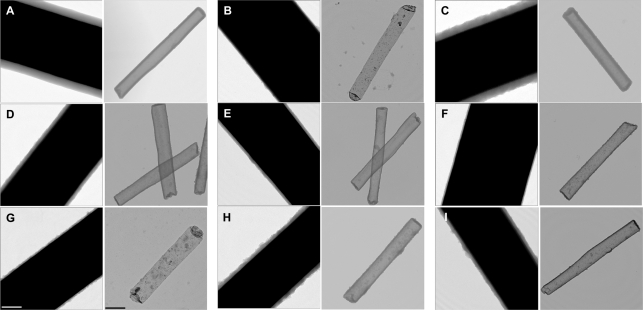
TEM imaging of the resulting ORMOSIL coatings on 6 μm Au nanowires was used to determine their mean thickness, which varied from just 6.0 ± 1.1 nm for three consecutive coatings with AcPTES-containing silica to 50.8 ± 2.6 nm for a single coating synthesized from TEOS. Representative images for each of the coating chemistries are shown in Figure 2 (left panels), and mean thicknesses are reported in Table 1. Low-magnification TEM images of TEOS, BTEB, BTMH, PEO, and NTPDI coated nanowires can be found in Supporting Information Figure 2, which confirms that little to no free silica was present in the sample, and that the nanowires were coated uniformly. ORMOSIL thickness varied with the length of the nanowires (i.e., available surface area for deposition), with thinner coatings for longer wires and thicker coatings for shorter wires. To allow for direct comparisons, all data presented in Figure 2 and Table 1 are for 6 μm Au nanowire coatings. TEM analysis also gave qualitative indications as to the homogeneity of the silica coating; some chemistries led to rougher, textured surfaces (and thus larger surface areas) leading to larger standard deviations in the thickness of the glass, for example, BTEB (Figure 2C) or NTPDI (Figure 2H), (Table 1). The differences in coating thickness and structure indicated, qualitatively, the differences in the silica coatings when different silicon alkoxide precursors are incorporated into the nanowire coatings.
Figure 2.
TEM images of silica-coated nanowires (left panels) and silica tubes (right panels) prepared from the following precursors: (A) TEOS (SiO2), (B) 3TEOS/1AcPTES (acryloxy group), (C) 10TEOS/1BTEB (ethyl benzene linker), (D) 3TEOS/1BTESE (ethane linker), (E) 2TEOS/1BTMH (hexane linker), (F) 3TEOS/1CETES (cyano group), (G) 4TEOS/1ICPTES (reacted isocyanato group), (H) 1TEOS/1NTPDI (dihydromidizole group), (I) 3TEOS/1PEO (polyethylene oxide group). Scale bars = 100 nm all left panels and 500 nm for right panels.
Exposure of the silica-coated nanowires to an acid solution resulted in dissolution of the metallic nanowires to form silica nanotubes (Scheme 1). TEM analysis showed these nanotubes to be intact, hollow structures replicating the nanowire size and shape (Figure 2, right panels). For a 3 μm nanowire, the resulting nanotube would have an estimated interior volume of ∼2 × 10⁻¹⁶ L. Depending on the thickness of the silica walls, nanotubes can be prone to collapse without the structural support of the nanowire scaffold when <10 nm thick; 3TEOS/1AcPTES and 4TEOS/1ICPTES tubes collapsed during drying or under vacuum, even with five coatings. Five coatings produced thick enough 3TEOS/1CETES and 3TEOS/1PEO silica to prevent collapse of the majority of tubes.
The different reaction conditions required for formation of the modified silica coatings, as well as their differences in morphology as compared to TEOS silica coating, suggested that the substituents were getting incorporated. Differences in the thickness and surface roughness of the various ORMOSILs may be due to changes in the reaction kinetics when different silicon alkoxides were incorporated into the reaction solution, thus changing the way in which the silanes were deposited onto the surface of the nanowires. Spectroscopic analysis of the coated nanowires and nanotubes was done to confirm that the different silicon alkoxide precursor molecules were getting incorporated.
Spectroscopic Analysis of Modified Silicas
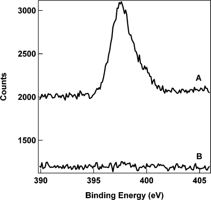
To verify the presence of the desired functional groups in the silica shells formed on the nanowires, we performed spectroscopic analysis of the coated nanowires and nanotubes. First, X-ray photoelectron spectroscopy (XPS) was performed on 1TEOS/1NTPDI coated nanowires, which were selected due to the presence of a nitrogen atom. High-resolution XPS indicated a peak at 397.6 eV in this sample, corresponding to the nitrogen 1s photoelectrons of the imidazole functionality (Figure 3). No corresponding peak was observed in the TEOS control sample. This confirmed that the addition of the imidazole-containing silicon alkoxide precursor into the reaction solution resulted in its incorporation in the silica coatings on the nanowire surface.
Figure 3.
High-resolution XPS data for the nitrogen 1s region for silica coated nanowires prepared from 1TEOS/1NTPDI (A) and TEOS (B).
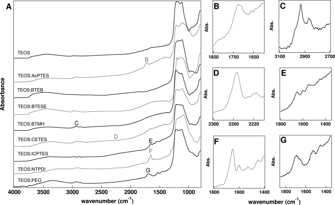
To further evaluate the incorporation of functionalized silicon alkoxides, the coated nanowires were analyzed using Fourier transform infrared spectroscopy using a diffuse reflection accessory. Figure 4 shows the resultant IR spectrum for each of the samples prepared, and Table 1 lists the characteristic peaks. A very strong band at ∼1300−960 cm−1 was observed in each spectrum; this peak is the Si−O−Si asymmetric stretch55−57 and was very intense due to the large number of cross-linked SiO2 in every sample. Given the intensity of this band, some of the peak distortion here is likely due to specular reflection of the sample. The functional groups were observed using FT-IR due to their characteristic vibrational signatures, confirming the incorporation into the silica coating on the nanowires. The presence of more pronounced CH2 asymmetric and symmetric stretches at 2932 cm−1 and 2864 cm−1, respectively,(57) in the BTMH sample with no other peaks observed other than the Si−O−Si stretch indicates the incorporation of this hexane-bridged silicon alkoxide. Likewise, peaks for other functional groups were observed, confirming the incorporation of these silicon alkoxides into the coating material (Table 1).(57) For example, the C=N functionality in the imidazole in the NTPDI sample absorbed at 1651 cm−1, while the C—N absorbed at 1601 cm−1.(57) The amide I and II groups of the PEO coating absorbed at 1692 cm−1 and 1530 cm−1, respectively.(57)
Figure 4.
(A) FT-IR spectra of TEOS and hybrid silica samples on Au nanowires. Characteristic peaks enlarged to the right: (B) carbonyl stretch of AcPTES; (C) alkyl stretch of BTMH; (D) cyano stretch of CETES; (E) peaks indicative of reacted ICPTES; (F) C=N stretch of NTPDI; (G) amide stretches of PEO.
We were unable to unambiguously identify the absorbance due to the C=C functionality in the AcPTES, BTEB, or BTESE materials. This is most likely due to the weak absorption of a carbon−carbon double bond and the low concentration, particularly with the BTEB sample (only 9% added benzene containing silicon alkoxide). The absence of the weak C=C mode in the spectra of the AcPTES, BTEB, or BTESE coated nanowires does not necessarily mean that these groups were absent from the coating on the nanowires; for example, the carbonyl peak at 1726 cm−1 is observed in the AcPTES sample, indicating the presence of the molecule in the coating, even though no C=C vibration was observed. We suspect that BTEB and BTESE may also have been incorporated based on the morphologies of the coatings and necessary modifications to the reaction conditions, but cannot confirm their presence.
It is also interesting to note that no strong peak at 2280 cm−1 was observed from the N=C=O functionality in the ICPTES sample, even after coating the nanowires with three ICPTES coatings.(55) Although this still produced a thin coating in comparison to other chemistries studied, 8.3 ± 2.3 nm, the isocyanate group should strongly absorb at 2300−2250 cm−1.(57) When compared to the TEOS spectrum, there were peaks present in the ICPTES spectrum not present in the TEOS spectrum. The peak at 1653 cm−1 suggested that the ICPTES was incorporated into the coating, but was converted to another species, possibly containing an amide group, due to the reactivity of isocyanates, specifically in the presence of water. It is well-known that isocyanates will react with hydroxyl groups to form urethanes.(58) The peak at 1653 cm−1 could be assigned to the carbonyl stretch, while the peaks at 1548 cm−1 and 1448 cm−1 may be the N−H bend and C−N stretch, respectively, lending evidence to the formation of urethane groups.57,59
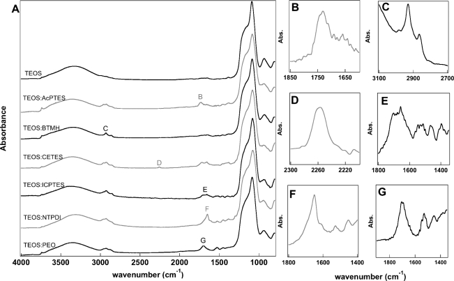
IR analysis of the silica nanotubes prepared by etching silica coated Au nanowires with aqua regia showed the varying functional groups remained present even after the strong acid etchant (Figure 5). IR analysis was done for the same modified silica materials analyzed above as nanowire coatings, except for the silicas containing the C=C functionalities (i.e., BTEB, BTESE), as these peaks were not observed with the initial analysis. New peaks at 3740 cm−1 were observed, corresponding to isolated silanols on the surface.(60) However, vibrational signatures of the functional groups remained, indicating that acid etch conditions did not result in loss of the organic groups.
Figure 5.
(A) FT-IR spectra of nanotubes composed of TEOS and each hybrid silica post acid etching. Identifying peaks enlarged to the right indicating presence of the functional peaks post etching: (B) carbonyl stretch of AcPTES; (C) alkyl stretch of BTMH; (D) cyano stretch of CETES; (E) peaks indicative of reacted ICPTES; (F) C=N stretch of NTPDI; (G) amide stretches of PEO.
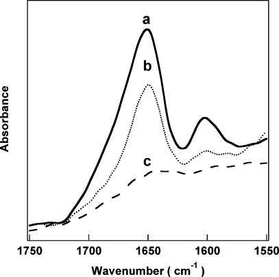
We then varied the ratio of TEOS to NTPDI to test whether this resulted in a change in the amount of modified silicon alkoxide incorporated into the nanowire coating. Supporting Information Figure 3 shows the TEM images of samples prepared with 10:1, 5:1, 3:1, 1:1, and 2:1 TEOS:NTPDI. When more NTPDI was added into the reaction mixture, thicker coatings were observed (Table 1). IR spectra were collected to determine if the concentration of NTPDI in the coating could be controlled, as indicated by the signature peak intensity. We were able to vary the amount incorporated qualitatively (Figure 6); however, a strong quantitative correlation between ratio of precursors added and the amount of functional group in the resulting glass was not observed due to day-to-day variability in the on-wire sol−gel reactions. It is clear from IR spectra of coated wires prepared and analyzed on separate days that the organically modified silane molecules were incorporated into the silica coating, but the exact amount varies due to a number of factors, e.g., the number of wires (loss of wires can occur during rinsing and due to adsorption to centrifuge tube walls), how well the wires are sonicated, the humidity, and so forth, thus contributing to the larger error bars observed in Supporting Information Figure 4.
Figure 6.
FT-IR spectra for silica coatings prepared using different amounts of imidazole-containing precursor: 1:1 TEOS/NTPDI (a), 10:1 TEOS/NTPDI (b), and TEOS alone (c).
Chromate Adsorption on Imidazole-Containing Silica Shells
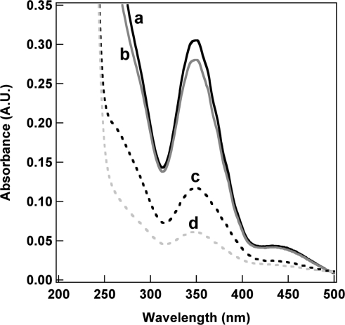
In a proof-of-concept experiment, NTPDI silica coatings were studied to further validate the presence and retained function of the modified silica. Bulk imidazole-containing sol−gel materials have been shown to chelate metal ions, such as chromate, and remove them from solution.8,9 To demonstrate that our ORMOSIL coatings retained the properties conferred by their functional groups in bulk ORMOSILs, we tested the ability of NTPDI-containing silica coated nanowires to remove chromate from solution, as compared to TEOS-silica coated nanowires. The nanowires were vortexed in chromate solution for a given amount of time, spun down, and the supernatant analyzed. Figure 7 shows UV−vis spectra of chromate in solution before and after contact with the coated nanowires. The chromate absorbed at ∼350 nm; a loss of 8.1% of the initially 19 μM chromate was observed upon introduction of the TEOS coated nanowires, presumably due to nonspecific binding. Nanowires with NTPDI incorporated into the silica coating removed a substantially larger amount of chromate from solution (62% and 80% for 10:1 and 1:1 TEOS/NTPDI coatings, respectively), as evident from the decreased chromate absorbance. Approximately an order of magnitude more chromate ions were adsorbed onto the 1TEOS/1NTPDI coated nanowires (1.5 × 10¹⁴/cm2) compared to the TEOS coated nanowires (1.3 × 10¹³/cm2), while ∼1.3 × 10¹⁴ chromate/cm2 was adsorbed onto the 10TEOS/1NTPDI coated nanowires. Integrated IR data for the coatings were prepared with different ratios of TEOS/NTPDI; twice as much NTPDI was incorporated into the silica coating when a 1:1 ratio of TEOS/NTPDI is used in the reaction mixture compared to 10:1 (Supporting Information Figure 4). These data suggest that not every imidazole group was accessible for chromate binding, potentially due to the inaccessibility of a greater percentage of groups in the 10:1 sample or charge repulsion leading to a saturation in chromate binding at higher surface densities.
Figure 7.
UV−vis absorbance for K2CrO4 supernatant before (a) and after incubation with silica coated nanowires prepared from: TEOS alone (b), 10:1 TEOS/NTPDI (c), and 1:1 TEOS/NTPDI (d).
Resistance of Protein Binding by PEO-Functionalized Silica Shells
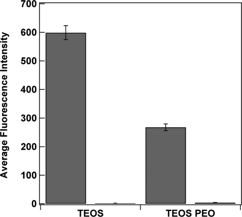
Although there are many advantages to SiO2 surfaces, such as well-understood attachment chemistry, structural support, relatively inert surface, and so forth, proteins are known to adsorb to the surfaces of materials, such as silica.61,62 This undesired adsorption of proteins onto the surface of silica materials needs to be minimized for specific applications, for example, biosensors or implantable devices.(61) The PEO moiety is attractive as a surface coating to resist protein adsorption and prevent biofouling.(63) We compared protein adsorption on PEO modified and standard SiO2 coated nanowires by suspending TEOS and TEOS/PEO coated gold nanowires in solutions of fluorescently labeled proteins. After incubation in a solution of either Alexa-Fluor 555-labeled lactate dehydrogenase (LDH) or Alexa-Fluor 488-labeled goat antimouse IgG, the nanowires were rinsed well with buffer and imaged on a fluorescence microscope (Supporting Information Figure 5). Figure 8 shows nanowires coated with the standard TEOS silica showed strong fluorescence after exposure to the fluorescent proteins; however, very little fluorescence was observed on the TEOS/PEO ORMOSIL coated nanowires, confirming their greater resistance to protein adsorption.
Figure 8.
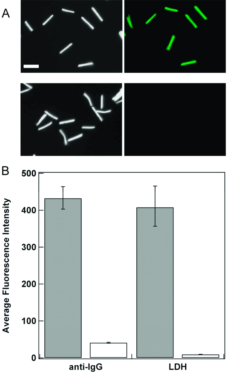
(A) Reflectance and fluorescence microscopy images of Alexa Fluor 555 LDH adsorbed onto TEOS coated Au nanowires (top images) and 3TEOS/1PEO coated Au nanowires (bottom images). (B) Mean intensity data for the adsorbed Alexa Fluor 555 LDH and Alexa Fluor 488 goat antimouse IgG (H+L) on the TEOS (gray) and 3TEOS/1PEO coated Au nanowires (white). Scale bar = 5 μm.
Surface Reaction of ORMOSIL Coatings
The organically modified silica coatings prepared here could also be surface functionalized analogously to standard inorganic silicas in order to attach molecules of interest such as DNA oligonucleotides. We verified this by attaching 5′-thiolated DNA oligonucleotides to the surface of silica and ORMOSIL coatings on metal nanowires and then incubating with fluorescent complementary or noncDNA oligonucleotides. Figure 9 compares fluorescence intensity data for these experiments on inorganic silica and TEOS/PEO coated nanowires. Differences in intensity for the complementary strand on the two samples can be understood in light of both the greater number of reactive groups and the greater separation between the dye molecule and the metal surface for the thicker TEOS coating as compared with TEOS/PEO. Nonetheless, both the standard TEOS silica and the TEOS/PEO exhibited good selectivity between the complementary and noncomplementary sequences.
Figure 9.
DNA oligonucleotide hybridization to covalently attached complementary probe strands on the ORMOSIL-coated nanowires. Thiolated probe DNA was covalently attached to coatings prepared from TEOS alone or TEOS/PEO coated Au nanowires, and mean fluorescence intensity of probe-coated particles was determined after incubation with fluorescently labeled complementary (gray) and noncDNA (white).
Conclusion
We have demonstrated the incorporation of organically modified precursor molecules with TEOS during sol−gel synthesis of silica shells on metallic nanowires. Most of the organically modified precursors evaluated here were successfully incorporated with minor modifications of the protocol used for standard TEOS glass shell formation, which suggests that additional functional groups not tested here should also be able to be incorporated without difficulty. A wide variety of modified silicon alkoxides with different functionalities and properties are commercially available and could potentially be used to synthesize ORMOSIL surface coatings on nanowires or other nano- or microparticulate scaffolds. Such coatings offer functionalities beyond those possible for traditional inorganic silica shells or the surface silanization approaches commonly used to vary the chemistry of these silica shells. Examples include the ability to incorporate desired organic groups covalently throughout the silica shell rather than just on the surface, to control porosity and provide permselectivity and enhanced protection against protein adsorption, biofouling, and/or corrosion.
Acknowledgments
This work was supported by the National Institute of Health (R01 EB000268-05 and R01 GM078352). S.L.D. also acknowledges a Pennsylvania Space Grant Consortium Graduate Research Fellowship for financial support. This publication was supported by the Pennsylvania State University Materials Research Institute Nano Fabrication Network and the National Science Foundation Cooperative Agreement No. 0335765, National Nanotechnology Infrastructure Network, with Cornell University. We appreciate the use of The Huck Institute for Life Sciences Electron Microscopy Facility. We thank Dr. Tad Daniel for assistance with XPS experiments, Vince Bojan for helpful discussions, Benjamin Smith for computer assistance, and William Aumiller, Jr., for providing fluorescently labeled lactate dehydrogenase.
Supporting Information Available
Reflectance optical microscopy images of acid-etched Au/Ni striped nanowires coated with TEOS/AcPTES silica coatings, low-magnification TEM images showing multiple silica coated nanowires for several different ORMOSILs on Au nanowires, TEM images of 10:1, 5:1, 3:1, 1:1, and 1:2 TEOS/NTPDI coated nanowires, IR quantification of amount of NTPDI functional group incorporated for the different TEOS/NTPDI ratios, and reflectance and fluorescence optical microscope images of labeled protein adsorbed to TEOS and PEO coated nanowires. This material is available free of charge via the Internet at http://pubs.acs.org.
Funding Statement
National Institutes of Health, United States
Supplementary Material
References
- Collinson M. M. Mikrochim. Acta 1998, 129, 149–165. [Google Scholar]
- Mackenzie J. D.; Bescher E. P. J. Sol-Gel Sci. Technol. 1998, 13, 371–377. [Google Scholar]
- Schmidt H. J. Non-Cryst. Solids 1985, 73, 681–691. [Google Scholar]
- Tripathi V. S.; Kandimalla V. B.; Ju H. Sens. Actuators, B 2006, 114, 1071–1082. [Google Scholar]
- Mackenzie J. D.; Bescher E. P. Acc. Chem. Res. 2007, 40, 810–818. [DOI] [PubMed] [Google Scholar]
- Walcarius A.; Collinson M. M. Annu. Rev. Anal. Chem. 2009, 2, 121–143. [DOI] [PubMed] [Google Scholar]
- Shea K. J.; Loy D. A.; Webster O. J. Am. Chem. Soc. 1992, 114, 6700–6710. [Google Scholar]
- Kang T.; Park Y.; Choi K.; Lee J. S.; Yi J. J. Mater. Chem. 2004, 14, 1043–1049. [Google Scholar]
- Park H.-J.; Tavlarides L. L. Ind. Eng. Chem. Res. 2008, 47, 3401–3409. [Google Scholar]
- Zheludkevich M. L.; Salvado I. M.; Ferreira M. G. S. J. Mater. Chem. 2005, 15, 5099–5111. [Google Scholar]
- Dash S.; Mishra S.; Patel S.; Mishra B. K. Adv. Colloid Interface Sci. 2008, 140, 77–94. [DOI] [PubMed] [Google Scholar]
- Jeong S.; Kim D.; Lee S.; Park B. K.; Moon J. Thin Solid Films 2007, 515, 7701–7705. [Google Scholar]
- Lee Y.-E. L.; Kopelman R. Wiley Interdiscipl. Rev. Nanomed. Nanobiotechnol. 2009, 1, 98–110. [DOI] [PubMed] [Google Scholar]
- Nicewarner-Peña S. R.; Freeman R. G.; Reiss B. D.; He L.; Peña D. J.; Walton I. D.; Cromer R.; Keating C. D.; Natan M. J. Science 2001, 294, 137–141. [DOI] [PubMed] [Google Scholar]
- Brunker S. E.; Cederquist K. B.; Keating C. D. Nanomedicine 2007, 2, 695–710. [DOI] [PubMed] [Google Scholar]
- a Stoermer R. L.; Cederquist K. B.; McFarland S. K.; Sha M. Y.; Penn S. G.; Keating C. D. J. Am. Chem. Soc. 2006, 128, 16892–16903. [DOI] [PMC free article] [PubMed] [Google Scholar]; b Cederquist K. B.; Golightly R. S.; Keating C. D. Langmuir 2008, 24, 9162–9171. [DOI] [PMC free article] [PubMed] [Google Scholar]; c Sha M. Y.; Yamanaka M.; Walton I. D.; Norton S. M.; Stoermer R. L.; Keating C. D.; Natan M. J.; Penn S. G. NanoBiotechnology 2005, 1, 327–335. [DOI] [PMC free article] [PubMed] [Google Scholar]
- Sioss J. A.; Stoermer R. L.; Sha M. Y.; Keating C. D. Langmuir 2007, 23, 11334–11341. [DOI] [PubMed] [Google Scholar]
- Keating C. D.; Natan M. J. Adv. Mater. 2003, 15, 451–454. [Google Scholar]
- Kotov N.; Tang Z.. Organization of Nanoparticles and Nanowires in Electronic Devices: Challenges, Methods and Perspectives. In Nanoparticle Assemblies and Superstructures, Kotov N. A., Ed.; Taylor and Francis Group: Boca Raton, 2006; pp 3−73. [Google Scholar]
- Kovtyukhova N. I.; Mallouk T. E. Chem.—Eur. J. 2002, 8, 4355–4363. [Google Scholar]
- a Qin L.; Banholzer M. J.; Xu X.; Huang L.; Mirkin C. A. J. Am. Chem. Soc. 2007, 129, 14870–14871. [DOI] [PubMed] [Google Scholar]; b Kline T. R.; Paxton W. F.; Mallouk T. E.; Sen A. Angew. Chem., Int. Ed. 2005, 44, 744–746. [DOI] [PubMed] [Google Scholar]; c Burdick J.; Laocharoensuk R.; Wheat P. M.; Posner J. D.; Wang J. J. Am. Chem. Soc. 2008, 130, 8164–8165. [DOI] [PubMed] [Google Scholar]
- Alkilany A. M.; Frey R. L.; Ferry J. L.; Murphy C. J. Langmuir 2008, 24, 10235–10239. [DOI] [PubMed] [Google Scholar]
- a Li C. Z.; He H. X.; Bogozi A.; Bunch J. S.; Tao N. J. Appl. Phys. Lett. 2000, 76, 1333–1335. [Google Scholar]; b Martin B. R.; St. Angelo S. K.; Mallouk T. E. Adv. Funct. Mater. 2002, 12, 759–765. [Google Scholar]; c Andrew P.; Ilie A. J. Phys. Conf. Ser. 2007, 61, 36–40. [Google Scholar]; d Bogozi A.; Lam O.; He H.; Li C.; Tao N. J.; Nagahara L. A.; Amlani I.; Tsui R. J. Am. Chem. Soc. 2001, 123, 4585–4590. [DOI] [PubMed] [Google Scholar]
- a Birenbaum N. S.; Lai B. T.; Chen C. S.; Reich D. H.; Meyer G. J. Langmuir 2003, 19, 9580–9582. [Google Scholar]; b Fond A. M.; Birenbaum N. S.; Felton E. J.; Reich D. H.; Meyer G. J. J. Photochem. Photobiol., A 2007, 186, 57–64. [Google Scholar]; c Tok J. B.-H.; Chuang F. Y. S.; Kao M. C.; Rose K. A.; Pannu S. S.; Sha M. Y.; Chakarova G.; Penn S. G.; Dougherty G. M. Angew. Chem., Int. Ed. 2006, 45, 6900–6904. [DOI] [PubMed] [Google Scholar]
- Kovtyukhova N. I.; Mallouk T. E.; Mayer T. S. Adv. Mater. 2003, 15, 780–785. [Google Scholar]
- Yin Y.; Lu Y.; Sun Y.; Xia Y. Nano Lett. 2002, 2, 427–430. [Google Scholar]
- Sioss J. A.; Keating C. D. Nano Lett. 2005, 5, 1779–1783. [DOI] [PubMed] [Google Scholar]
- Gorelikov I.; Matsuura N. Nano Lett. 2008, 8, 369–373. [DOI] [PubMed] [Google Scholar]
- Bumb A.; Brechbiel M. W.; Choyke P. L.; Fugger L.; Eggeman A.; Prabhakaran D.; Hutchinson J.; Dobson P. J. Nanotechnology 2008, 19, 1–6. [DOI] [PMC free article] [PubMed] [Google Scholar]
- a Mulvaney S. P.; Musick M. D.; Keating C. D.; Natan M. J. Langmuir 2003, 19, 4784–4790. [Google Scholar]; b Doering W. E.; Nie S. Anal. Chem. 2003, 75, 6171–6176. [DOI] [PubMed] [Google Scholar]
- Hsia C.-H.; Yen M.-Y.; Lin C.-C.; Chiu H.-T.; Lee C.-Y. J. Am. Chem. Soc. 2003, 125, 9940–9941. [DOI] [PubMed] [Google Scholar]
- Obare S. O.; Jana N. R.; Murphy C. J. Nano Lett. 2001, 1, 601–603. [Google Scholar]
- Hunyadi S. E.; Murphy C. J. J. Phys. Chem. B 2006, 110, 7226–7231. [DOI] [PubMed] [Google Scholar]
- Fan R.; Wu Y.; Li D.; Yue M.; Majumdar A.; Yang P. J. Am. Chem. Soc. 2003, 125, 5254–5255. [DOI] [PubMed] [Google Scholar]
- Mitchell D. T.; Lee S. B.; Trofin L.; Li N.; Nevanen T. K.; Söderlund H.; Martin C. R. J. Am. Chem. Soc. 2002, 124, 11864–11865. [DOI] [PubMed] [Google Scholar]
- Bae C.; Yoo H.; Kim S.; Lee K.; Kim J.; Sung M. M.; Shin H. Chem. Mater. 2008, 20, 756–767. [Google Scholar]
- Gasparac R.; Kohli P.; Mota M. O.; Trofin L.; Martin C. R. Nano Lett. 2004, 4, 513–516. [Google Scholar]
- a Meegan J. E.; Aggeli A.; Boden N.; Brydson R.; Brown A. P.; Carrick L.; Brough A. R.; Hussain A.; Ansell R. J. Adv. Funct. Mater. 2004, 14, 31–37. [Google Scholar]; b Shenton W.; Douglas T.; Young M.; Stubbs G.; Mann S. Adv. Mater. 1999, 11, 253–256. [Google Scholar]
- Kim M.; Hong J.; Lee J.; Hong C. K.; Shim S. E. J. Colloid Interface Sci. 2008, 322, 321–326. [DOI] [PubMed] [Google Scholar]
- Chen Y.; Xue X.; Wang T. Nanotechnology 2005, 16, 1978–1982. [Google Scholar]
- a Liu S.; Han M.-Y. Chem. Asian J. 2010, 5, 36–45. [DOI] [PubMed] [Google Scholar]; b Caruso R. A.; Antonietti M. Chem. Mater. 2001, 13, 3272–3282. [Google Scholar]; c Caruso F. Adv. Mater. 2001, 13, 11–22. [Google Scholar]; d Mulvaney P.; Liz-Marzán L. M.; Giersig M.; Ung T. J. Mater. Chem. 2000, 10, 1259–1270. [Google Scholar]
- Lu Y.; Yin Y.; Li Z.-Y.; Xia Y. Nano Lett. 2002, 2, 785–788. [Google Scholar]
- Hardikar V. V.; Matijević E. J. Colloid Interface Sci. 2000, 221, 133–136. [DOI] [PubMed] [Google Scholar]
- Liz-Marzán L. M.; Giersig M.; Mulvaney P. Langmuir 1996, 12, 4329–4335. [Google Scholar]
- Graf C.; Vossen D. L. J.; Imhof A.; van Blaaderen A. Langmuir 2003, 19, 6693–6700. [Google Scholar]
- a Jin Y.; Li A.; Hazelton S. G.; Liang S.; John C. L.; Selid P. D.; Pierce D. T.; Zhao J. X. Coord. Chem. Rev. 2009, 253, 2998–3014. [Google Scholar]; b Jiang X.; Brinker C. J. J. Am. Chem. Soc. 2006, 128, 4512–4513. [DOI] [PubMed] [Google Scholar]; c Martini M.; Perriat P.; Montagna M.; Pansu R.; Julien C.; Tillement O.; Roux S. J. Phys. Chem. C 2009, 113, 17669–17677. [Google Scholar]
- a Al-Mawlawi D.; Liu C. Z.; Moskovits M. J. Mater. Res. 1994, 9, 1014–1018. [Google Scholar]; b Hulteen J. C.; Martin C. R. J. Mater. Chem. 1997, 7, 1075–1087. [Google Scholar]; c Kline T. R.; Tian M.; Wang J.; Sen A.; Chan M. W. H.; Mallouk T. E. Inorg. Chem. 2006, 45, 7555–7565. [DOI] [PubMed] [Google Scholar]
- Use caution when working with aqua regia, as it will cause severe burns. Dispose of strong acid properly.
- All spectra were acquired using: a midband MCT detector, 3.0 mm internal aperture, and a 40.0 kHz scanning velocity. The interferograms were processed using a Mertz phase correction, Norton-Beer medium apodization, and a zerofilling factor of 8.
- Blitz J. P.Diffuse Reflectance Spectroscopy. In Modern Techniques in Applied Molecular Spectroscopy, Mirabella F. M., Ed.; Techniques in Analytical Chemistry; John Wiley & Sons, Inc.: New York; pp 185−219. [Google Scholar]
- Bertoluzza A.; Fagnano C.; Morelli M. A.; Gottardi V.; Guglielmi M. J. Non-Cryst. Solids 1982, 48, 117–128. [Google Scholar]
- Samuels A. C.; Zhu C.; Williams B. R.; Ben-David A.; Miles R. W. Jr.; Hulet M. Anal. Chem. 2006, 78, 408–415. [DOI] [PubMed] [Google Scholar]
- Walton I. D.; Norton S. M.; Balasingham A.; He L.; Oviso D. F. Jr.; Gupta D.; Raju P. A.; Natan M. J.; Freeman R. G. Anal. Chem. 2002, 74, 2240–2247. [DOI] [PubMed] [Google Scholar]
- Brinker C. J.; Scherer G. W.. Hydrolysis and Condensation II: Silicates. In Sol-Gel Science: The Physics and Chemistry of Sol-Gel Processing; Academic Press, Inc.: Boston, 1990; pp 97−234. [Google Scholar]
- Silverstein R. M.; Webster F. X.; Kiemle D. J.. Infrared Spectrometry. In Spectrometric Identification of Organic Compounds, 7th ed.; John Wiley & Sons, Inc.: New Jersey, 2005; pp 72−126. [Google Scholar]
- a Guiton T. A.; Pantano C. G. Colloids Surf., A 1993, 74, 33–46. [Google Scholar]; b Almeida R. M.; Pantano C. G. J. Appl. Phys. 1990, 68, 4225–4232. [Google Scholar]
- Socrates G.Infrared and Raman Characteristic Group Frequencies Tables and Charts, 3rd ed.; John Wiley & Sons, Ltd.: Chichester, 2001. [Google Scholar]
- Clayden J.; Greeves N.; Warren S.; Wothers P.. Polymerization. In Organic Chemistry; Oxford University Press: Oxford, 2001; p 1458. [Google Scholar]
- Seo Y.-K.; Park S.-B.; Park D. H. J. Solid State Chem. 2006, 179, 1285–1288. [Google Scholar]
- Brinker C. J.; Scherer G. W.. Surface Chemistry and Chemical Modifications. In Sol-Gel Science: The Physics and Chemistry of Sol-Gel Processing; Academic Press, Inc.: Boston, 1990; p 620. [Google Scholar]
- Nakanishi K.; Sakiyama T.; Imamura K. J. Biosci. Bioeng. 2001, 91, 233–244. [DOI] [PubMed] [Google Scholar]
- Parida S. K.; Dash S.; Patel S.; Mishra B. K. Adv. Colloid Interface Sci. 2006, 121, 77–110. [DOI] [PubMed] [Google Scholar]
- a Herrwerth S.; Eck W.; Reinhardt S.; Grunze M. J. Am. Chem. Soc. 2003, 125, 9359–9366. [DOI] [PubMed] [Google Scholar]; b Prime K. L.; Whitesides G. M. Science 1991, 252, 1164–1167. [DOI] [PubMed] [Google Scholar]
Associated Data
This section collects any data citations, data availability statements, or supplementary materials included in this article.


