

Abstract
Mechanical testing of collagenous tissues at different length scales will provide improved understanding of the mechanical behavior of structures such as skin, tendon, and bone, and also guide the development of multiscale mechanical models. Using a microelectromechanical-systems (MEMS) platform, stress-strain response curves up to failure of type I collagen fibril specimens isolated from the dermis of sea cucumbers were obtained in vitro. A majority of the fibril specimens showed brittle fracture. Some displayed linear behavior up to failure, while others displayed some nonlinearity. The fibril specimens showed an elastic modulus of 470 ± 410 MPa, a fracture strength of 230 ± 160 MPa, and a fracture strain of 80% ± 44%. The fibril specimens displayed significantly lower elastic modulus in vitro than previously measured in air. Fracture strength/strain obtained in vitro and in air are both significantly larger than those obtained in vacuo, indicating that the difference arises from the lack of intrafibrillar water molecules produced by vacuum drying. Furthermore, fracture strength/strain of fibril specimens were different from those reported for collagenous tissues of higher hierarchical levels, indicating the importance of obtaining these properties at the fibrillar level for multiscale modeling.
Introduction
Significant effort has been put into developing improved methods to assess risk of bone fracture related to osteoporosis and to link known genetic defects to mechanical deficiencies arising from diseases like osteogenesis imperfecta (OI) and Ehlers Danlos syndrome. These efforts include multiscale modeling and experimental studies aimed at isolating the mechanical behavior of relevant tissues at discrete length scales. Multiscale molecular dynamics simulation has been used to study single collagen molecules (1–3) and single collagen fibrils made of multiple collagen molecules (4,5). Buehler and co-workers demonstrated the effects of cross-link density (6) and mineralization (7) on the mechanical properties of collagen fibrils. They also showed that single-point mutation of collagen molecules in OI results in softer collagen molecules (8) and softer and weaker collagen fibrils (9), which contributed to a better understanding of the molecular and microscopic mechanisms underlying OI. Experimental probing at specific length-scales arises from the need to provide constitutive parameter inputs for multiscale models and to test these models to ensure they agree with measurement. As part of this larger effort, we have worked on providing measurements of isolated collagen fibrils. In this article, we present our first measurements of fibrils tested in bulk saline solution showing load to failure for 13 different test specimens.
There are only a few studies testing the mechanical properties of collagen fibrils. Small angle x-ray scattering (10–13) was used to detect deformation of collagen fibrils inside tissue samples. This clever investigation separated molecular stretching seen in the collagen molecular helix diffraction signature from molecular sliding seen from the D-spacing diffraction signature. However, forces were not directly applied to individual fibrils, but calculated from the total force applied to the bulk tendon. This resulted in plots of the average response of thousands of fibrils rather than the response of single fibrils. The statistical power of such a study is quite high, but the ability to investigate individual failure mechanisms of a fibril is impeded by the averaging procedure. Recently, atomic force microscopy (AFM) was used to perform tensile (14,15), bending (16–18), and nanoindentation (19–22) tests on individual collagen fibrils. These are elegant studies that benefit from using instrumentation widely available to many investigators. However, the tensile and three-point bending experiments were limited to strains of only a few percent and thus did not provide any strength or toughness data. Nanoindentation was successfully used to investigate elastic modulus and hardness of single fibrils. Because of tip curvature, the actual loading of the fibril is complex. It is expected that the majority of the applied force is along the fibril radial direction with some force vectors also pointing along the axial direction. In general, we consider this technique to be complementary to our microelectromechanical systems (MEMS) technique with indentation providing primarily radial direction mechanics and MEMS providing primarily axial direction mechanics.
We previously developed a MEMS technique to perform uniaxial tensile tests on collagen fibrils in air at relative humidities of 31–60% (23,24). While our previous reports showed large strain behavior of fibrils with well-defined boundary conditions, the devices used were limited to applicable strains of ∼100% and applicable loads of ∼35 μN, and the devices could not be actuated in bulk water. These tests mimicked physiologically relevant conditions better than in vacuo tests, but the lack of bulk water surrounding the fibrils remained an issue of concern. In addition, while we were able to break a few fibrils previously, the majority required larger loads and displacements than our device could apply. We have overcome all these problems with the device used in the study reported below.
Water is a major constituent of collagenous tissues and an important contributor to their mechanical behavior. A high-resolution x-ray crystallography study (25) showed that a collagen-like peptide was surrounded by a highly structured network of water molecules, and neighboring collagen helices did not directly contact one another. Instead, water molecules mediated the interaction between them. Another study (26) made direct measurements of force-distance curves between collagen triple helices by coupling the osmotic-stress technique with x-ray diffraction. The external force from osmotic pressure dehydrated the collagen fibrils resulting in diminished interaxial spacing of the molecules within each fibril. Dry collagen fibrils had an interaxial molecular spacing of 12 Å, whereas hydrated fibrils had an interaxial spacing up to 18.5 Å. Therefore, collagen molecules within hydrated fibrils were separated by a water layer up to 6.5 Å thick. A later Raman spectrum study (27) showed that the water within the fibril was not bulk-like and continuously rearranged its H-bonding network as pressure was applied to the fibril. This internal water might be expected to affect the mechanical properties of the fibril in several ways. By pushing collagen molecules apart, it would act to decrease interaction strength among collagen molecules thereby weakening the fibrils. Concomitantly, hydrogen bonding among the waters could act as a stabilizing force-impeding glide between adjacent molecules. Finally, hydrogen bonding between the internal waters and specific amino-acid residues is expected to contribute to the overall stability of each collagen molecule, by forcing its minima, with respect to rotation and stretching, to occur at positions different than those for the dehydrated or semihydrated fibril. An earlier differential scanning calorimetry study (28) confirmed this general line of argument by showing that the glass transition temperature of gelatins containing collagen-like structures decreased with increasing water content, suggesting that the bound water acted as a natural plasticizer.
At the tissue level, altering water content of collagenous tissues affects their elastic and viscous behavior. A nanoindentation study (29) on millimeter-scale rectangular cortical bone samples demonstrated that elastic modulus increased by more than a factor of 2 from a wet to a dehydrated state. Another study used Brillouin light scattering to test rat tail tendon at different relative humidity conditions (30). The elastic moduli of the tendon collagen fibril bundles were calculated from the sound velocity and tissue density. The results showed elastic modulus decreased from 20 to 9 GPa when the relative humidity increased from 0% to 85%, respectively. A study on ligaments (31) showed that ligaments with higher water content (soaked in hypotonic solutions) displayed greater cyclic load relaxation compared to those with lower water content (soaked in hypertonic solutions). Other experiments done on ligaments showed that creep decreases with decreasing hydration (32,33). Another work on tendons (34) showed that tendons relaxed faster in hypotonic solutions than in hypertonic solutions.
At the fibrillar level, we expect collagen fibrils to behave differently under different hydration states. In this article, we present stress-strain data from 13 type I collagen fibril specimens tested in vitro using a MEMS device showing, for the first time to our knowledge, the in vitro fracture behavior of isolated collagen fibrils. The results are discussed in comparison with our previous in air study (24), with larger collagenous structures (35,36), and with molecular dynamics simulations (6,37).
Materials and Methods
MEMS devices
MEMS devices designed and fabricated to test collagen fibrils in vitro were similar to those used previously for in air studies (23,24). A typical MEMS device (Fig. 1 a) contained a fixed pad (labeled FP), a movable pad (labeled MP), a force gauge pad (labeled FGP), a force gauge (labeled FG), a pushing hole (labeled PH), four anchor pads (labeled A), and four tether beams (labeled T). One-hundred-mm-diameter silicon wafers were sequentially coated with 3.5 μm of sacrificial SiO2, and 6 μm of polycrystalline Si (polysilicon), via low-pressure chemical vapor deposition. Devices were patterned using optical lithography, then the polysilicon was etched in a SF6 plasma. The remaining photoresist was removed in aqueous H2SO4/H2O2, and devices were released by immersion in aqueous hydrofluoric acid for 32 min, followed by rinsing in methanol and critical point CO2 drying. The release etch dissolved all the sacrificial SiO2 beneath the movable portions of the polysilicon device (labeled T, FG, FGP and MP in Fig. 1 a). The majority of the sacrificial SiO2 beneath the large areas (labeled A and FP in Fig. 1 a) remained to anchor the device.
Figure 1.
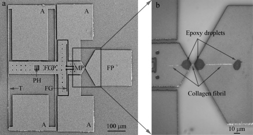
Representative second-generation MEMS device for collagen fibril in vitro fracture test. (a) A low magnification SEM image of MEMS device, consisting of a fixed pad (FP), a movable pad (MP), a force gauge pad (FGP), anchors (A), and tether beams (T). Compared with the first-generation MEMS device used in a previous in-air study (24), two new features were added, including a pushing hole (PH) which allows a sharp probe to mechanically push the device and a force gauge (FG) consisting of two tether beams connecting FGP and MP for force measurement. (b) An optical image of a collagen fibril specimen fixed onto a MEMS device. Three micron-size epoxy droplets were used to fix the specimen, including one on the movable pad and two on the fixed pad. Three portions of collagen fibril specimen were visible. The middle portion (between movable pad and fixed pad) was the testing piece used for in vitro fracture test. The right portion (between the two epoxy droplets on the fixed pad) was used for diameter measurement.
Each experiment began by fixing a fibril specimen between the fixed and movable pads as described previously (23,24). A sharp probe placed inside the pushing hole enabled relative motion between fixed and movable portions of the device resulting in uniaxial tension applied to the specimen. Four tether beams provided support to the movable portion and ensured guidance of motion in a uniaxial manner. A two-beam force gauge was used to measure the force applied to the specimen. Each force gauge beam is 2.1-μm wide, 100-μm long, and 6-μm thick. Given the geometry of these beams and the material properties of polysilicon (e.g., Young's modulus = 160 GPa and Poisson's ratio = 0.22), the force needed to deform the force gauge beam to a given displacement was modeled using nonlinear finite element analysis. Thus, a load-displacement response of the force gauge was obtained. The maximum force measurable before fracture of the force gauge beams was ∼17.5 mN, which was ∼500 times larger than the maximum force of our previous comb-drive-actuated devices, ∼35 μN (24).
Sample preparation
Type I collagen fibrils were isolated from the dermis of sea cucumber, Cucumaria frondosa (38) (see section S1 in the Supporting Material for details). The fibrils were visualized in solution using dark-field illumination because they were too thin to be visualized in bright-field. Glass capillary tubes (TW100F-4, 1 mm OD/0.75 mm ID; World Precision Instruments, Sarasota, FL) were pulled using a micropipette puller (PB-7; Narishige International USA, East Meadow, NY) to fabricate glass micropipettes with tip diameters smaller than 1 μm. The pulled micropipette attached to a hydraulic micromanipulator (MMO-203; Narishige, Tokyo, Japan) was used to transfer a specimen out of a 1–2 μL solution droplet and position it across the two MEMS device pads (labeled MP and FP in Fig. 1 a). Once one fibril was attached to the pipette and we began to translate it toward the air/water interface, a few other fibrils were often entrained in the motion of the pipette tip. We only loaded specimens between the pads that appeared by dark-field imaging to be single fibrils. The specimen was fixed to the MEMS device using another pulled glass micropipette attached to a separate micromanipulator (ITW Devcon, Danvers, MA) to apply two small epoxy droplets (5 min and 30 min epoxies mixed in a 1:1 ratio) over the ends of the specimen close to the edges of the movable and fixed pads. A third epoxy droplet was placed on the fixed pad farther away from the edge (Fig. 1 b) to facilitate cross-sectional area measurement after the specimen had fractured. After in vitro fracture testing, it was difficult to find the specimen in the gauge region so the portion of specimen on the fixed pad between the two epoxy droplets was used to obtain cross-sectional area measurements. Though it required considerable skills, one could reliably align a fibril specimen across the device >80% of the time with enough practice and good manipulators. We intentionally designed the movable and fixed pads of the device to have a triangular shape, so the vertices pointing toward the gauge region could help the fibril alignment. The experiments failed if the fibrils were picked up by the probe that was used to deposit epoxy droplets. Once a fibril specimen was successfully fixed to a MEMS device, the epoxy droplets were allowed to cure overnight in a covered petri dish containing wet lint-free tissue papers (Kimtech Science Kimwipes; Kimberly-Clark, Dallas, TX). As we demonstrated in a previous in-air study (24), the epoxy droplets remain localized and do not spread along the fibril. Briefly, we fixed a fibril to a MEMS device, and then labeled it with fluorescent antibodies. Under fluorescence imaging, antibodies clearly adhered to the fibril in the gauge region and not the epoxy. Thus, antigenic sections of the collagen surfaces were still accessible for antibody binding after the epoxy was applied, indicating that the epoxy remained on the pads and did not spread along the fibril. After the epoxy droplets cured, ∼200 μL 1× phosphate-buffered saline was placed on the MEMS device completely immersing the specimen. The specimen was allowed to rehydrate by storing it in a 4°C refrigerator for at least 24 h before the fracture test. Each MEMS device can only be used once because there are epoxy droplets left on the pads from the first use and the movable portions of the device become stuck to the substrate when the solution evaporates.
In vitro fracture test procedure
MEMS devices with fibril specimens attached were mounted on a piezo stage (P-517; Physik Instruments, Auburn, MA), and a sharp probe (either tungsten or pulled glass micropipette, with a tip diameter of ∼10 μm) was placed in the pushing hole (labeled PH in Fig. 1 a) holding the movable portion of the device stationary. The fixed portion of the device was moved together with the piezo stage at a displacement rate of ∼34 nm/s until the test specimen fractured. A 60× water immersion objective lens (Fluor 60×; Nikon, Tokyo, Japan) was used to visualize the devices in phosphate-buffered saline. A digital camera (Micropublisher 3.3 RTV; QImaging, Surrey, BC, Canada) was used to capture images at a frame rate of either 0.2, 0.4, or 0.5 fps while the specimens were being stretched in vitro at room temperature. The displacement controlled by the piezo stage and the sharp probe was the total displacement of the MEMS device, which equals the sum of the fibril specimen displacement and the force gauge displacement (i.e., dtotal = dfibril specimen + dforce gauge). There was no way to independently control the displacement of the fibril specimen or the displacement of the force gauge (i.e., the applied force). Thus, we did not have a simple displacement-control or force-control testing system.
Force-displacement curves obtained by digital image correlation
To obtain force-displacement curves, images of the MEMS device collected during the fracture test were compared with the zero load image using digital image correlation (DIC). DIC has the ability to detect rigid body motions with precision better than the Abbe diffraction limit (39,40). The technique utilizes grayscale information in the image and applies it using multi-image location analysis as opposed to the better-known single image in-plane resolution analysis. Three separate sets of markers for DIC were chosen to monitor the rigid body displacements of the fixed pad (d1), the movable pad (d2), and the force gauge pad (d3), respectively. Custom-written MATLAB code based on the code developed by Eberl et al. (41) was used to track the positions of the markers and determine the rigid body displacements of the regions of interest (see Fig. S1 a in the Supporting Material). Elongation of the fibril specimen was calculated by comparing relative displacements of the movable and fixed pads, dfibril specimen = d1 – d2 (Fig. S1 b). Deformation of the force gauge was obtained by subtracting displacement of the force gauge pad from displacement of the movable pad, dforce gauge = d2 – d3 (Fig. S1 b). Deformation of the force gauge was converted to force applied to the specimen using the force-displacement response obtained via finite element analysis. Thus, force-displacement curves of fibrils were obtained (Fig. S1 c).
Stress-strain curves
Force-displacement curves were used to calculate nominal stress-engineering strain curves. We recognize that for experiments associated with large strain and significant reduction in cross-sectional area, the true stress (force divided by instantaneous area) and a higher-order strain may be preferable. However, our choice allows for direct comparison with the molecular dynamics results of Buehler (4,6,7) and Tang et al. (37) for the same measures, and eliminates the need to measure the change in cross-sectional area during testing (which we are unable to do). True strengths are likely larger than what we report and the qualitative shapes of stress-strain curves may change when using true stress and a large strain measure such as logarithmic strain. The nominal stress is given by
where F and A0 are applied force and initial cross-sectional area, respectively. The engineering strain is given by
where d and l0 are the measured change in length and the initial gauge length. The value l0 was measured as the distance between the edges of the two epoxy droplets on either end of the gauge region. Scanning electron microscopy (SEM S4500; Hitachi, Tokyo, Japan) and atomic force microscopy (AFM, Multimode Nanoscope IV; Veeco Instruments, Plainview, NY) were used to record radial and axial lengths needed to obtain A0 and l0, respectively. We expected fibrils to dehydrate in the SEM vacuum chamber resulting in aberrantly small radial measurements. To account for differences between the in vacuo SEM measured cross-sectional area and the in vitro cross-sectional area during fracture testing, we performed a separate calibration experiment using AFM in liquid and SEM in vacuo (see sections S2 and S3 in the Supporting Material for details). This allowed us to determine a multiplicative enlargement factor of 4.85, which is necessary to convert the in vacuo SEM measured areas to in vitro mechanically tested areas. In other words, the fibril diameter in vitro is times as large as that in vacuo. AFM imaging of fibrils in liquid is difficult and time-consuming due to difficulty in locating the fibril and moving the AFM tip to the fibril. There is also risk of breaking the MEMS devices when performing the coarse approach to make contact. The purpose of performing this separate AFM experiment is that once we have established the conversion factor, we no longer need to do it for every fibril.
Results
SEM images of collagen fibril specimens
Fig. 2 shows SEM images of two collagen fibril specimens on the fixed pads of their respective MEMS devices. The cobblestone appearance of polysilicon grains is seen in Fig. 2 a. The fibril specimen running from left to right in the middle of Fig. 2 a is roughly cylindrical with a relatively smooth surface. This smooth cylindrical appearance was typical (nine out of 13 specimens) and consistent with SEM fibril specimen images in our prior in air studies (23,24). Although we could distinguish the smooth fibril specimen from the rough polysilicon surface, a more straightforward fibril diameter measurement could be made if the polysilicon surface was smooth. To achieve such a smooth substrate, we coated seven MEMS devices with polyimide before fixing specimens to them. Fig. 2 b shows a collagen fibril specimen on a polyimide-coated fixed pad. In addition to the polyimide coating, this specimen was prepared with a different sputter coater than the one used to produce the image in Fig. 2 a. (All specimens were sputter-coated with ∼5-nm-thick film of palladium before SEM observation to enhance conductivity and image resolution.) The specimen in Fig. 2 b shows the characteristic D-banding pattern of collagen fibrils and appears to be three fibrils (indicated by arrowheads) twisted about one another. Four out of 13 fibril specimens showed D-banding and all four of them showed multiple D-banding consistent with two or three fibrils coiled about each other. Polyimide coating alone was not the reason that we saw D-banding, because some specimens fixed onto polyimide-coated MEMS devices did not show any D-banding, whereas some specimens fixed onto uncoated devices did show D-banding. The appearance of D-banding was more likely related to the use of different sputter coaters. However, under no circumstances were we able to reproducibly obtain D-banded patterns.
Figure 2.
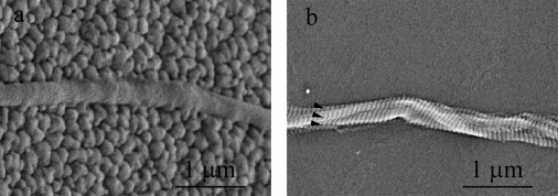
Two high magnification SEM images of collagen fibril specimens. (a) The specimen appeared to be a single fibril on an uncoated fixed pad. The fixed pad showed the typical grains of polysilicon and had a cobblestone-like appearance. The collagen fibril specimen appeared to be a cylinder with a relatively smooth surface, running from left to right in the middle section. No clear D-banding pattern of the specimen was observed. This is not uncommon in SEM imaging of collagen fibrils because the appearance of D-banding pattern of collagen fibrils highly depends on the sample preparation and imaging equipment. (b) The specimen appeared to be multiple fibrils entangled together and twisted with one another on a fixed pad coated with polyimide. The fixed pad appeared to be relatively smooth because of the polyimide coating. Multiple D-banding patterns (arrowheads in b) clearly indicate the existence of multiple fibrils (approximately three fibrils in this case).
In our previously published tests, SEM images of all fibril specimens appeared smooth and did not show any D-banding pattern (see Fig. 1 b in (23) and Fig. 2 b in (24)), leading us to conclude that we had tested individual collagen fibrils. In light of the four specimens showing multiple D-banding patterns in our study and because the same method was used to manipulate fibrils in all our studies, we now entertain the possibility that all our tests may have been done on small groups of entangled fibrils. Only two or three fibrils were identified by SEM, suggesting that mechanical signatures attributable to single fibrils should be readily measureable in our load-deformation tests.
Stress-strain curves obtained from in vitro fracture test
In vitro fracture tests were performed on 13 collagen fibril specimens. The in vacuo measured specimen diameter is in the range of 93–411 nm, similar to that reported previously (38). Considering the swelling due to hydration, the in vacuo diameter was enlarged 2.20 times to obtain the in vitro diameter range of 205–905 nm. The gauge lengths ranged from 6.0 to 18.0 μm. Each specimen was monotonically stretched to fracture at a displacement rate of 34 ± 1 nm/s, which corresponded to strain rates of 0.2–0.6% per second. This range in strain rates existed because, even though we used a constant loading rate, each specimen had a different gauge length determined by the spacing between the epoxy droplets holding the test specimen down. The variability in mechanical behavior can be categorized into three groups:
-
1.
Linear response to brittle fracture (six specimens).
-
2.
Multiple linear regions with discrete slopes before brittle fracture (five specimens).
-
3.
Multiple linear regions followed by a stepwise graceful fracture region (two specimens).
The multiple D-banding patterns mentioned above were distributed among all three types of behavior. However, the two specimens in Group III, which displayed graceful failure, had much larger diameters (657 nm and 905 nm) than the other 11 specimens in Group I and II. It is likely that the stepwise graceful failure region is a result of multiple fibrils.
Fig. 3 shows the mechanical response of four representative collagen fibril specimens. Error bars indicate the measurement uncertainty (see section S4 in the Supporting Material for details). The specimen in Fig. 3 a was from Group I and fractured at a stress (strain) of 290 MPa (53%). The specimen in Fig. 3 b was from Group II and was fit with a single change of slope at a stress (strain) of 90 MPa (6%), and eventually fractured at a stress (strain) of 380 MPa (66%). The specimen in Fig. 3 c was also from Group II and showed a double change of slope, with a stress (strain) of 150 MPa (31%) at the first intersection point and a stress (strain) of 240 MPa (59%) at the second intersection point, and eventually fractured at a stress (strain) of 270 MPa (99%). The specimen in Fig. 3 d was from Group III and showed multiple linear regions with a double change of slope at a stress (strain) of 20 MPa (12%) and a stress (strain) of 50 MPa (39%), followed by a stepwise graceful failure region (indicated by the open arrowheads), and fractured at a stress (strain) of 40 MPa (126%). Individual stress-strain curves of the other specimens are shown in Fig. S4, Fig. S5, and Fig. S6.
Figure 3.
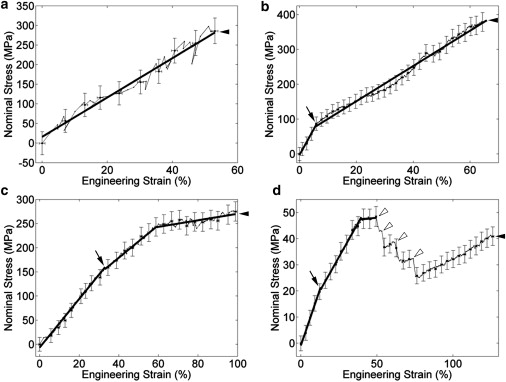
Mechanical behavior of four representative collagen fibril specimens. The four specimens display differing behavior during the in vitro fracture test, as follows: (a) relatively linear behavior all the way to brittle fracture; (b) two linear regions with a single change of slope before brittle fracture; (c) three linear regions with a double change of slope before brittle fracture; and (d) three linear regions with a double change of slope before a stepwise graceful fracture region. For the sake of clarity, the error bars are shown every five data points. (Thick solid lines) Least-squares fits to relatively linear regions. The initiation of damage is defined as the intersection of the first two fitted lines (indicated by arrows). The fracture point is defined as the point where the stress dropped back to zero (indicated by solid arrowheads). (d) Multiple drops in the graceful fracture region (indicated by open arrowheads), suggesting multiple partial fractures before the complete fracture (solid arrowhead).
Mechanical properties obtained from the stress-strain curves
Mechanical properties of collagen fibrils such as elastic modulus, strength/strain at the initiation of damage, fracture strength/strain, and toughness, were measured from the stress-strain curves and will be discussed in the following subsections. The two specimens in Group III had much larger diameters and likely consisted of more fibrils than the other 11 specimens. Thus, we only used the 11 specimens in Group I and II, with diameters ranging from 205 nm to 448 nm, for the following analysis.
Elastic modulus
All 11 specimens showed initial linear regions which were least-squares fitted to single lines. The small strain elastic modulus obtained from the slopes of the fitted lines was 470 ± 410 MPa (mean ± SD; range, 110–1470 MPa; n = 11).
Strength/strain at the initiation of damage
The five specimens in Group II showed nonlinear behavior which was least-squares fitted to multiple lines. Previous in-air experiments showed, using unloading curves, that nonelastic behavior was present during loading (24). Thus, the nonlinear behavior seen in our in vitro tests may be attributed to the initiation of irreversible deformation mechanisms including the breaking of cross-links. Based on this assumption, we defined the initiation of damage as the intersection of the first two fitted lines (arrows in Fig. 3). The strength at the initiation of damage was 150 ± 120 MPa (mean ± SD; range, 30–350 MPa; n = 5), while the strain at the initiation of damage was 24% ± 20% (mean ± SD; range, 6–55%; n = 5).
Fracture strength/strain
The fracture point was defined as the first point followed by a dramatic unrecovered drop in the stress (solid arrowheads in Fig. 3). The in vitro fracture strength was 230 ± 160 MPa (mean ± SD; range, 40–490 MPa; n = 11), while the in vitro fracture strain was 80% ± 44% (mean ± SD; range, 33–183%; n = 11).
Toughness
The toughness, defined as the area underneath the stress-strain curve up to the fracture point, was 140 ± 180 × 106 J/m3 (mean ± SD; range, 7–660 × 106 J/m3; n = 11). As explained in a previous molecular dynamics simulation study, because fibril specimens have relatively large aspect ratios (length/diameter > 10), they can be associated with snap-back instabilities in their force-displacement response; both force and displacement decrease in the postpeak region (see Fig. 7 in (37)). However, our fracture tests cannot capture the potential snap-back response. As a consequence, the toughness we reported here is likely an overestimation of the energy dissipated in the failure process.
The spread in the mechanical properties reported above is relatively large. The possible reasons are explained in section S5 in the Supporting Material.
Discussion
Comparison of mechanical properties of collagen fibrils obtained in vitro versus in air versus in vacuo
Previous work showed specimens tested under ambient air conditions behaved differently from vacuum-dried conditions (24). In that study, only three out of 13 specimens broke when tested in air, while all seven specimens broke when tested after exposure to dehydration in the SEM vacuum chamber. This was attributed to intrafibrillar water present in the semihydrated in air samples that was removed by vacuum drying. The data presented in this article were obtained from specimens surrounded by bulk water during testing. Mechanical properties of collagen fibril specimens (including elastic modulus, fracture strength, and fracture strain) obtained under these different experimental conditions (in vitro, in air, and in vacuo) are shown in Fig. 4. Specimens usually broke at very small strains after exposure to dehydration in vacuo, resulting in insufficient data points for determining the elastic modulus in vacuo. Thus, elastic modulus is only shown for the in vitro and in air cases.
Figure 4.
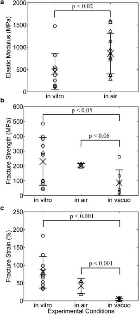
Comparison of mechanical properties of collagen fibril specimens obtained at different experimental conditions (i.e., in vitro, in air, and in vacuo), including the (a) elastic modulus, (b) fracture strength, and (c) fracture strain. The data obtained in vitro, in air, and in vacuo were displayed by symbols ○, ▵, and □, respectively. The mean and standard derivation of each mechanical property are indicated by × and the error bar. The elastic modulus obtained in vitro was significantly lower than that obtained in air (panel a). The fibril specimens tested after imaging in the SEM vacuum chamber fractured at significantly smaller strength (panel b) and strain (panel c) than those tested in vitro and in air. Due to the large data scattering and limited number of data points, other mechanical properties (data not shown) did not show statistically significant differences when tested at different experimental conditions.
Fig. 4 a shows the elastic modulus obtained in vitro (470 MPa) is significantly lower than that obtained in air (860 MPa). Our in vitro results (110–1470 MPa) are in reasonable agreement with earlier results obtained in aqueous conditions using nanobending (70–170 MPa) (18) and force spectroscopy (200–800 MPa) (15). However, our result is two to three orders of magnitude larger than that obtained in nanoindentation (1.2 ± 0.1 MPa) (21). This is probably a reflection of anisotropy in mechanical properties which arises from the axial and radial alignment of the collagen molecules within the fibril. Our finding that collagen fibrils had a lower modulus in vitro than in air also agrees with previous axial load deformation studies on collagen fibrils (15,18). This trend is consistent with the findings of Leikin et al. (26), who showed that increasing states of hydration lead to increasing intermolecular radial spacing within collagen fibrils. Furthermore, an NMR titration method utilizing spin-lattice relaxation at different levels of hydration developed by Fullerton and co-workers (42,43) was used to investigate the structural arrangement of water molecules around collagen molecules during sequential dehydration of bovine flexor tendon. They showed that there are three changes in water motion with hydration level:
-
1.
At low hydration with correspondingly short intermolecular separation, a single water bridge (Ramachandran water bridge (44)) forms every three peptide residues between a positive amide group on one α-chain and a negative carbonyl group on another α-chain in the same collagen molecule.
-
2.
At intermediate hydration with correspondingly intermediate intermolecular separation, three additional water molecules per tripeptide bind in a hydrogen-bonded network to the collagen as well as the Ramachandran water bridge to form a four water-molecule chain (Berendsen water chain or cleft water) per tripeptide in the molecular grooves of the collagen triple helix.
-
3.
At native full hydration with correspondingly large intermolecular separation, full monolayer coverage forms with six water chains per cleft or 18 water chains per collagen molecule.
In other words, with increasing water content and increasing intermolecular separation, the water molecules around a collagen molecule continuously change their structural arrangement from single water bridges to water chains and then to a monolayer of interfacial water. Because the interaction forces between molecules in a fibril are inversely proportional to their separation distance, the more highly hydrated fibrils are expected to show both more freedom to rotate without impinging on their neighbors (intramolecular contribution to modulus) as well as more freedom to slide axially with respect to their neighbors (intermolecular contribution to modulus).
Fig. 4 b shows a monotonic trend of decreasing fracture strength going from in vitro (230 MPa) to in air (200 MPa) to in vacuo (90 MPa). Similarly, Fig. 4 c shows a monotonic trend of decreasing fracture strain going from in vitro (80%) to in air (42%) to in vacuo (4%). Assigning statistical significance to this trend is complicated by the fact that we were only able to break three of the fibril specimens using our previous-generation electrostatically actuated devices (the devices used to collect all the in-air data reported in this article). The very tight grouping of the in vacuo data does, however, allow us to assign statistical significance to that data mean, it being lower than either of the others. Evidently, the plasticizing effect water has on collagen (28) is present under both in vitro and in air conditions but is extinguished upon vacuum dehydration. Moreover, the amount of water needed to obtain plasticization is not able to reenter the vacuum-dried fibril specimens over a time period of a few hours after being reintroduced to ambient air conditions.
Comparison with larger collagenous structures (i.e., fibril bundles, fascicles, and tendons)
Some mechanical properties determined at the fibrillar level were different from those obtained from larger collagenous structures in the literature (13,35,36,46,47) (see Table S1 in the Supporting Material), indicating the importance of testing these mechanical properties at the fibrillar level for multiscale modeling. There was a relatively clear trend in the fracture strain, which decreased from 80% (1–3 fibrils, present work) to 22% (fibril bundles (35)), 11% (fascicles (36)), and 6% (tendon (36)). In other words, the fracture strain decreased with increasing specimen diameter. This suggests one of two possible failure mechanisms for collagen tissue substructures. First, larger structures fail by slippage among fibrils rather than by fracture of individual fibrils. Second, defects within larger structures result in stress concentrations with concomitantly high localized strains causing fibrils at the point of failure to fracture, while the overall strain of the larger assembly never gets much larger than 10%.
While the fracture strength of collagen fibril specimens was higher than those obtained from larger structures (35,36), there was no clear trend in the fracture strength with respect to the diameters of these different structures. This is consistent with the failure mechanism proposed involving failure by slippage among fibrils rather than fracture of individual fibrils. It is known that ground substance exists in all the structures larger than fibrils. If ground substance is weaker than the collagen fibril, then the larger structure will fracture in the ground substance at a lower strength than the fibril. Once the ground substance is introduced at the suprafibrillar level, fracture strengths are expected to remain approximately constant.
For elastic modulus, our fibrillar data were comparable to studies at fibril bundle, fascicle, and tissue levels. The finding that collagen fibrils had a similar elastic modulus to larger collagenous structures suggests that individual fibrils rather than the other components, such as interfibrillar cross-links and/or interfibrillar glycosaminoglycan bridges, determine the stiffness of collagenous tissues.
Comparison with molecular dynamics simulation
A molecular dynamics simulation by Buehler (6) demonstrated that collagen fibrils could show dissipative deformation after yield when the fibril had a low cross-link density, or have a brittle-like deformation when the fibril had a high cross-link density. However, Buehler's initial fibril model (6) contained only two collagen molecules along the fibril length. A more recent study using the same model applied to longer test pieces (37) demonstrated that fibrils of at least 10 molecules along their length exhibited only brittle fracture with no graceful ductile-like character.
The minimum length of our tested specimens was 6 μm. Assuming the length of a collagen molecule is 300 nm (48), our fibril specimens contain at least 20 collagen molecules along the fibril length. According to the findings by Tang et al. (37), we should only observe brittle failure. Indeed, a majority (11 out of 13, in Group I and II) of the fibril specimens displayed brittle behavior, while the two in Group III which showed graceful failure had the largest diameters and consisted of many fibrils. It is likely that the stepwise graceful fracture of the two fibrils in Group III is attributable to their multiple fibril construction. One model that would explain this involves having fibrils of unequal lengths within the gauge region. The shortest fibril reaches its failure point first, causing a stepwise drop before the remaining fibrils pick up the load. This could occur multiple times until finally the entire remaining specimen fails. Another model to explain the stepwise behavior, even if the multiple fibrils have similar lengths in the gauge region, involves a specimen in which some fibrils are weaker than others (e.g., containing more defects). The weakest fibril in the specimen fractures first. At the moment when this fibril breaks, the force applied to the remaining specimen stays the same but the stress increases because of the decreased cross-sectional area. This increased stress strains the specimen considerably causing it to elongate. As mentioned in Materials and Methods, we can only control the total displacement of the MEMS device, which equals the sum of the fibril specimen displacement and the force gauge displacement (i.e., dtotal = dfibril specimen + dforce gauge). Thus, when the specimen elongates, the force gauge displacement decreases, resulting in a decreased measured load producing a drop in the plotted stress-strain curve when a fibril breaks. The other fibrils in the remaining specimen would hold the load until the next weakest fibril breaks. This process repeats until all fibrils in the specimen break. One reason why this stepwise behavior might not be seen with the smaller fibrils is that if only two or three fibrils exist in the gauge region to start, failure of one fibril might be sufficient to overload the remaining fibrils causing the whole system to fail at once. This would lead to the observed brittle failure seen with the smaller diameter test specimens.
The fracture strains (33–183%) of collagen fibril specimens obtained in this experiment agree well with those (10–125%) obtained via molecular dynamics simulation (37). This indicates that the choice of input parameters used in the molecular dynamics simulation of Tang et al. (37) were appropriate for obtaining a match with our in vitro experiment. The elastic modulus and the fracture strength of collagen fibrils determined from our in vitro experiments, however, were one to two orders of magnitude lower than the computational results. As Buehler (6) and Tang et al. (37) pointed out, this is an expected discrepancy because the theoretical model used an extremely large deformation rate compared to experimentally or physiologically relevant rates. In addition, their models did not consider spatial inhomogeneities of cross-link distributions, changes of molecular properties along the molecular length, and realistic size boundary condition. All these factors result in larger elastic modulus and larger fracture strength of collagen fibrils from the molecular dynamics simulation compared with the experiments.
Another possibly important discrepancy between the molecular dynamics model and our experiments involves water. In Buehler's molecular dynamics simulation (1,4,6), full-atomistic modeling with explicit water was used to study individual collagen molecules and assemblies of two collagen molecules. These results were used to derive parameters for the mesoscale molecular dynamics simulation in which each collagen molecule was represented by beads connected by different types of springs. The geometry used during the explicit water part of the computation allowed for bulk water bonding to occur in almost every direction moving radially away from the collagen. In a real fibril, the presence of nearest-neighbor collagen molecules prevents bulk water bonding from occurring inside the fibril. Because water contributes a large portion of the total energy of formation in the collagen fibril system, this may play a large role in defining the mechanics of the system.
Conclusions
We performed in vitro fracture tests on type I collagen fibril specimens isolated from sea cucumber dermis using MEMS devices. We obtained stress-strain curves from 13 specimens with diameters in the range of 205–905 nm, which to our knowledge are the first measurements of in vitro fracture behavior of these biologically ubiquitous submicron-size objects. Three types of different mechanical behavior were observed, including
-
1.
A relatively linear region all the way to brittle fracture.
-
2.
Multiple linear regions before brittle fracture.
-
3.
Multiple linear regions followed by a stepwise graceful fracture region.
A majority (11 out of 13) of the specimens showed brittle failure, while the two largest specimens showed graceful failure which may be a result of multiple fibrils. After excluding the two largest specimens, we found an elastic modulus of 470 ± 410 MPa, a fracture strength of 230 ± 160 MPa, a fracture strain of 80% ± 44%, and a toughness of 140 ± 180 × 106 J/m3 in vitro. The collagen fibril specimens displayed statistically significantly lower elastic modulus in vitro than in air. However, there are no statistically significant differences in the other mechanical properties such as the fracture strength, the fracture strain, and the toughness when comparing the in vitro study to the in air study. Both the fracture strength and fracture strain obtained in vitro and in air are significantly larger than those obtained in vacuo, indicating the difference rises from the lack of intrafibrillar water molecules produced by vacuum drying. Some mechanical properties of collagen fibrils, such as the fracture strength and fracture strain, were significantly different from those obtained at the fibril bundle, fascicle, and tissue levels, confirming the importance of obtaining these properties at the fibrillar level for multiscale hierarchical modeling. Future work could include a study of the effect of cross-link density, genetic variation, and mineralization on the mechanical properties of collagen fibrils.
Acknowledgments
We thank Prof. John A. Trotter of the University of New Mexico for providing the collagen fibrils, Prof. Ioannis Chasiotis and Dr. Mohammad Naraghi of the University of Illinois at Urbana-Champaign for help on DIC, and Prof. Markus J. Buehler of the Massachusetts Institute of Technology for enlightening conversation.
This work was funded by National Science Foundation grant No. 0532320 and National Institutes of Health grant No. 1 R21 EB004985-01A1. The content is solely the responsibility of the authors and does not necessarily represent the official views of the National Science Foundation or the National Institute of Health. This investigation was conducted in a facility constructed with support from Research Facilities Improvement Program grant No. C06 RR12463-01 from the National Center for Research Resources, National Institutes of Health. Z.L.S. was supported by an Innovation Incentive Fellowship grant from the Ohio Board of Regents. R.B. acknowledges the support by National Science Foundation grant NSF CMMI 0800896.
Footnotes
Mohammad Reza Dodge's present address is College of Optical Sciences, University of Arizona, Tucson, AZ.
Contributor Information
Roberto Ballarini, Email: broberto@umn.edu.
Steven J. Eppell, Email: sje@case.edu.
Supporting Material
References
- 1.Buehler M.J. Atomistic and continuum modeling of mechanical properties of collagen: elasticity, fracture, and self-assembly. J. Mater. Res. 2006;21:1947–1961. [Google Scholar]
- 2.Gautieri A., Buehler M.J., Redaelli A. Deformation rate controls elasticity and unfolding pathway of single tropocollagen molecules. J. Mech. Behav. Biomed. Mater. 2009;2:130–137. doi: 10.1016/j.jmbbm.2008.03.001. [DOI] [PubMed] [Google Scholar]
- 3.Buehler M.J., Wong S.Y. Entropic elasticity controls nanomechanics of single tropocollagen molecules. Biophys. J. 2007;93:37–43. doi: 10.1529/biophysj.106.102616. [DOI] [PMC free article] [PubMed] [Google Scholar]
- 4.Buehler M.J. Nature designs tough collagen: explaining the nanostructure of collagen fibrils. Proc. Natl. Acad. Sci. USA. 2006;103:12285–12290. doi: 10.1073/pnas.0603216103. [DOI] [PMC free article] [PubMed] [Google Scholar]
- 5.Buehler M.J. Molecular architecture of collagen fibrils: a critical length scale for tough fibrils. Curr. Appl. Phys. 2008;8:440–442. [Google Scholar]
- 6.Buehler M.J. Nanomechanics of collagen fibrils under varying cross-link densities: atomistic and continuum studies. J. Mech. Behav. Biomed. Mater. 2008;1:59–67. doi: 10.1016/j.jmbbm.2007.04.001. [DOI] [PubMed] [Google Scholar]
- 7.Buehler M.J. Molecular nanomechanics of nascent bone: fibrillar toughening by mineralization. Nanotechnology. 2007;18:1–9. [Google Scholar]
- 8.Gautieri A., Vesentini S., Buehler M.J. Single molecule effects of Osteogenesis Imperfecta mutations in tropocollagen protein domains. Protein Sci. 2009;18:161–168. doi: 10.1002/pro.21. [DOI] [PMC free article] [PubMed] [Google Scholar]
- 9.Gautieri A., Uzel S., Buehler M.J. Molecular and mesoscale mechanisms of Osteogenesis Imperfecta disease in collagen fibrils. Biophys. J. 2009;97:857–865. doi: 10.1016/j.bpj.2009.04.059. [DOI] [PMC free article] [PubMed] [Google Scholar]
- 10.Sasaki N., Odajima S. Elongation mechanism of collagen fibrils and force-strain relations of tendon at each level of structural hierarchy. J. Biomech. 1996;29:1131–1136. doi: 10.1016/0021-9290(96)00024-3. [DOI] [PubMed] [Google Scholar]
- 11.Puxkandl R., Zizak I., Fratzl P. Viscoelastic properties of collagen: synchrotron radiation investigations and structural model. Philos. Trans. R. Soc. Lond. B Biol. Sci. 2002;357:191–197. doi: 10.1098/rstb.2001.1033. [DOI] [PMC free article] [PubMed] [Google Scholar]
- 12.Gupta H.S., Seto J., Fratzl P. Cooperative deformation of mineral and collagen in bone at the nanoscale. Proc. Natl. Acad. Sci. USA. 2006;103:17741–17746. doi: 10.1073/pnas.0604237103. [DOI] [PMC free article] [PubMed] [Google Scholar]
- 13.Misof K., Rapp G., Fratzl P. A new molecular model for collagen elasticity based on synchrotron x-ray scattering evidence. Biophys. J. 1997;72:1376–1381. doi: 10.1016/S0006-3495(97)78783-6. [DOI] [PMC free article] [PubMed] [Google Scholar]
- 14.Graham J.S., Vomund A.N., Grandbois M. Structural changes in human type I collagen fibrils investigated by force spectroscopy. Exp. Cell Res. 2004;299:335–342. doi: 10.1016/j.yexcr.2004.05.022. [DOI] [PubMed] [Google Scholar]
- 15.van der Rijt J.A., van der Werf K.O., Feijen J. Micromechanical testing of individual collagen fibrils. Macromol. Biosci. 2006;6:697–702. doi: 10.1002/mabi.200600063. [DOI] [PubMed] [Google Scholar]
- 16.Heim A.J., Koob T.J., Matthews W.G. Low strain nanomechanics of collagen fibrils. Biomacromolecules. 2007;8:3298–3301. doi: 10.1021/bm061162b. [DOI] [PubMed] [Google Scholar]
- 17.Yang L., van der Werf K.O., Feijen J. Micromechanical bending of single collagen fibrils using atomic force microscopy. J. Biomed. Mater. Res. A. 2007;82:160–168. doi: 10.1002/jbm.a.31127. [DOI] [PubMed] [Google Scholar]
- 18.Yang L., van der Werf K.O., Feijen J. Mechanical properties of native and cross-linked type I collagen fibrils. Biophys. J. 2008;94:2204–2211. doi: 10.1529/biophysj.107.111013. [DOI] [PMC free article] [PubMed] [Google Scholar]
- 19.Heim A.J., Matthews W.G., Koob T.J. Determination of the elastic modulus of native collagen fibrils via radial indentation. Appl. Phys. Lett. 2006;89:181902. [Google Scholar]
- 20.Wenger M.P.E., Bozec L., Mesquida P. Mechanical properties of collagen fibrils. Biophys. J. 2007;93:1255–1263. doi: 10.1529/biophysj.106.103192. [DOI] [PMC free article] [PubMed] [Google Scholar]
- 21.Grant C.A., Brockwell D.J., Thomson N.H. Effects of hydration on the mechanical response of individual collagen fibrils. Appl. Phys. Lett. 2008;92:233902. [Google Scholar]
- 22.Grant C.A., Brockwell D.J., Thomson N.H. Tuning the elastic modulus of hydrated collagen fibrils. Biophys. J. 2009;97:2985–2992. doi: 10.1016/j.bpj.2009.09.010. [DOI] [PMC free article] [PubMed] [Google Scholar]
- 23.Eppell S.J., Smith B.N., Ballarini R. Nano measurements with micro-devices: mechanical properties of hydrated collagen fibrils. J. R. Soc. Interface. 2006;3:117–121. doi: 10.1098/rsif.2005.0100. [DOI] [PMC free article] [PubMed] [Google Scholar]
- 24.Shen Z.L., Dodge M.R., Eppell S.J. Stress-strain experiments on individual collagen fibrils. Biophys. J. 2008;95:3956–3963. doi: 10.1529/biophysj.107.124602. [DOI] [PMC free article] [PubMed] [Google Scholar]
- 25.Bella J., Eaton M., Berman H.M. Crystal and molecular structure of a collagen-like peptide at 1.9 Å resolution. Science. 1994;266:75–81. doi: 10.1126/science.7695699. [DOI] [PubMed] [Google Scholar]
- 26.Leikin S., Rau D.C., Parsegian V.A. Direct measurement of forces between self-assembled proteins: temperature-dependent exponential forces between collagen triple helices. Proc. Natl. Acad. Sci. USA. 1994;91:276–280. doi: 10.1073/pnas.91.1.276. [DOI] [PMC free article] [PubMed] [Google Scholar]
- 27.Leikin S., Parsegian V.A., Walrafen G.E. Raman spectral evidence for hydration forces between collagen triple helices. Proc. Natl. Acad. Sci. USA. 1997;94:11312–11317. doi: 10.1073/pnas.94.21.11312. [DOI] [PMC free article] [PubMed] [Google Scholar]
- 28.Tseretely G.I., Smirnova O.I. DSC study of melting and glass-transition in gelatins. J. Therm. Anal. 1992;38:1189–1201. [Google Scholar]
- 29.Bembey A.K., Koonjul V., Boyde A. Contribution of collagen, mineral and water phases to the nanomechanical properties of bone. Mater. Res. Soc. Symp. Proc. 2005 [Google Scholar]
- 30.Harley R., James D., White J.W. Phonons and the elastic moduli of collagen and muscle. Nature. 1977;267:285–287. doi: 10.1038/267285a0. [DOI] [PubMed] [Google Scholar]
- 31.Chimich D., Shrive N., Bray R. Water content alters viscoelastic behavior of the normal adolescent rabbit medial collateral ligament. J. Biomech. 1992;25:831–837. doi: 10.1016/0021-9290(92)90223-n. [DOI] [PubMed] [Google Scholar]
- 32.Hoffman A.H., Robichaud D.R., 2nd, Grigg P. Determining the effect of hydration upon the properties of ligaments using pseudo Gaussian stress stimuli. J. Biomech. 2005;38:1636–1642. doi: 10.1016/j.jbiomech.2004.07.032. [DOI] [PubMed] [Google Scholar]
- 33.Thornton G.M., Shrive N.G., Frank C.B. Altering ligament water content affects ligament pre-stress and creep behavior. J. Orthop. Res. 2001;19:845–851. doi: 10.1016/S0736-0266(01)00005-5. [DOI] [PubMed] [Google Scholar]
- 34.Haut T.L., Haut R.C. The state of tissue hydration determines the strain-rate-sensitive stiffness of human patellar tendon. J. Biomech. 1997;30:79–81. doi: 10.1016/s0021-9290(96)00108-x. [DOI] [PubMed] [Google Scholar]
- 35.Miyazaki H., Hayashi K. Tensile tests of collagen fibers obtained from the rabbit patellar tendon. Biomed. Microdevices. 1999;2:151–157. [Google Scholar]
- 36.Yamamoto E., Hayashi K., Yamamoto N. Mechanical properties of collagen fascicles from the rabbit patellar tendon. J. Biomech. Eng. 1999;121:124–131. doi: 10.1115/1.2798033. [DOI] [PubMed] [Google Scholar]
- 37.Tang Y., Ballarini R., Eppell S.J. Deformation micromechanisms of collagen fibrils under uniaxial tension. J. R. Soc. Interface. 2010;7:839–850. doi: 10.1098/rsif.2009.0390. [DOI] [PMC free article] [PubMed] [Google Scholar]
- 38.Trotter J.A., Lyons-Levy G., Koob T.J. Covalent composition of collagen fibrils from the dermis of the sea cucumber, Cucumaria frondosa, a tissue with mutable mechanical properties. Comp. Biochem. Physiol. Physiol. 1995;112:463–478. [Google Scholar]
- 39.Naraghi M., Chasiotis I., Dzenis Y. Novel method for mechanical characterization of polymeric nanofibers. Rev. Sci. Instrum. 2007;78:085108. doi: 10.1063/1.2771092. [DOI] [PubMed] [Google Scholar]
- 40.Naraghi M., Chasiotis I., Dzenis Y. Mechanical deformation and failure of electrospun polyacrylonitrile nanofibers as a function of strain rate. Appl. Phys. Lett. 2007;91:151901. [Google Scholar]
- 41.Eberl, C., R. Thompson, …, K. Hemker. 2006. Digital image correlation and tracking. http://www.mathworks.com/matlabcentral/fileexchange/12413.
- 42.Fullerton G.D., Nes E., Cameron I. An NMR method to characterize multiple water compartments on mammalian collagen. Cell Biol. Int. 2006;30:66–73. doi: 10.1016/j.cellbi.2005.09.009. [DOI] [PubMed] [Google Scholar]
- 43.Fullerton G.D., Amurao M.R. Evidence that collagen and tendon have monolayer water coverage in the native state. Cell Biol. Int. 2006;30:56–65. doi: 10.1016/j.cellbi.2005.09.008. [DOI] [PubMed] [Google Scholar]
- 44.Ramachandran G.N., Chandrasekharan R. Interchain hydrogen bonds via bound water molecules in the collagen triple helix. Biopolymers. 1968;6:1649–1658. doi: 10.1002/bip.1968.360061109. [DOI] [PubMed] [Google Scholar]
- 45.Reference deleted in proof.
- 46.Screen H.R., Lee D.A., Shelton J.C. An investigation into the effects of the hierarchical structure of tendon fascicles on micromechanical properties. Proc. Inst. Mech. Eng. H. 2004;218:109–119. doi: 10.1243/095441104322984004. [DOI] [PubMed] [Google Scholar]
- 47.Derwin K.A., Soslowsky L.J. A quantitative investigation of structure-function relationships in a tendon fascicle model. J. Biomech. Eng. 1999;121:598–604. doi: 10.1115/1.2800859. [DOI] [PubMed] [Google Scholar]
- 48.Kadler K.E., Holmes D.F., Chapman J.A. Collagen fibril formation. Biochem. J. 1996;316:1–11. doi: 10.1042/bj3160001. [DOI] [PMC free article] [PubMed] [Google Scholar]
Associated Data
This section collects any data citations, data availability statements, or supplementary materials included in this article.