Abstract
Purpose: To develop a 4D volumetric modulated arc therapy (VMAT) inverse planning framework.
Methods: 4D VMAT inverse planning aims to derive an aperture and weight modulated arc therapy treatment plan that optimizes the accumulated dose distribution from all gantry angles and breathing phases. Under an assumption that the gantry rotation and patient breathing are synchronized (i.e., there is a functional relationship between the phase of the patient breathing cycle and the beam angle), the authors compute the contribution from different respiration phases through the registration of the phased CT images. The accumulative dose distribution is optimized by iteratively adjusting the aperture shape and weight of each beam through the minimization of the planning objective function. For comparison, traditional 3D VMAT plans are also performed for the two cases and the performance of the proposed technique is demonstrated.
Results: A framework for 4D VMAT inverse planning has been proposed. With the consideration of the extra dimension of time in VMAT, a tighter target margin can be achieved with a full duty cycle, which is otherwise not achievable simultaneously by either 3D VMAT optimization or gated VMAT.
Conclusions: The 4D VMAT planning formulism proposed here provides useful insight on how the “time” dimension can be exploited in rotational arc therapy to maximally compensate for the intrafraction organ motion.
Keywords: VMAT, inverse planning, intensity modulation, dose optimization, arc therapy
INTRODUCTION
Volumetric modulated arc therapy (VMAT) is an advanced form of rotational arc radiation therapy,1, 2, 3, 4, 5, 6, 7, 8, 9 which produces conformal dose distribution through the modulation of beam shape and weight while gantry rotates continuously. By spreading out the delivered dose angularly through a continuous arc delivery, VMAT has the potential to improve sparing of organs-at-risk (OARs) and reduce treatment time. Practically, a limiting factor that may hinder the maximal utilization of VMAT dose delivery scheme is the intrafractional organ motion when treating tumors in the thorax or upper abdomen. Several studies based on fluoroscopic and 4D imaging have revealed that the intrafraction motion can be as large as 0.5–5 cm for tumors in these regions.10, 11 The actual received dose distribution of the patient may well differ from the planned distribution if the intrafractional anatomy change is not taken into account properly.12 Commonly, a large safety planning target volume (PTV) margin is used in VMAT to avoid possible target miss, which unavoidably irradiates a large amount of adjacent normal tissues with high doses and thus increases the toxicity. Respiratory gating is an option in fixed-gantry IMRT to reduce the PTV margin.10, 13, 14, 15 Gated VMAT is possible at the cost of increased duty cycle of dose delivery, but requires frequent stopping of the heavy LINAC gantry during dose delivery.
A 4D plan optimization strategy16, 17, 18 presents a logical solution to account for the intrafractional organ motion. In essence, 4D VMAT is an extension of the 4D IMRT scheme, first proposed by Trofimov et al.,16 to rotational arc therapy. In this delivery, the beam aperture and weight at each angle are determined by minimizing the difference between the prescribed dose and the accumulative dose from all phases and gantry angles. Coupled with the recent advances in real-time monitoring of tumor motion and MLC-based tracking, this delivery scheme may become a viable choice in future radiation therapy armamentarium. An important and necessary step toward the realization of 4D VMAT is the development of an effective treatment planning framework. In this work, we provide a feasibility study of such an inverse planning formalism and demonstrate the potential advantage of 4D VMAT.
MATERIALS AND METHODS
Formulation of 4D VMAT inverse planning
The aim of 4D VMAT planning is to find a series of beam segments with optimal beam weight wθ and segment shape, defined by the coordinates of leaf ends {xθ,A,xθ,B} or each gantry angle θ. A quadratic objective function is utilized to find the 4D VMAT solution19
| (1) |
where is the prescription dose for the ith structure, n is the voxel index, Dc(n) is the calculated dose distribution over voxel index, σi,1 and σi,2 are weighting factors for underdosing and overdosing of the structure i, Ni is the total number of voxels of the structure i, and H(x) is the Heaviside step function (it takes 1 for positive x and 0 otherwise). In this objective function, a penalty is applied to the voxels that receive doses higher than the upper-bound or lower than the lower-bound . For OARs, the lower-bound dose is set to zero and only overdosing of the structures is penalized.
In 4D VMAT treatment planning, the dose to a voxel is a superposition of the doses from all phases and segmented fields at different gantry angles. For a given phase, the dose distribution is computed by summing the contribution from each segment or gantry angle. When multiple phases are involved, a deformable registration model is used to track the movement of each voxel. The cumulative dose is expressed as
| (2) |
where Ka(n) is the dose at a voxel n from the segment depicted by aθp with unit intensity and waθp is the weight of aperture aθp. Tp→r is the matrix that links voxels of a voxel in a phase (p) to the reference phase (r) through the use of a deformable model, which transforms the dose contribution computed in the pth phase into the dose in the rth (reference) phase. In some special cases (e.g., when only the target moves back and forth in the system), however, the registration matrix takes a simple form and the 4D dose calculation is thus simplified.
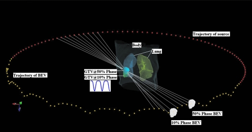
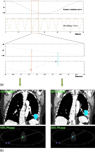
For demonstration of principle, an assumption is made that the gantry rotation and patient breathing are synchronized, such that there is a functional relationship p=p(θ) between the breathing phase p and the gantry angle θ. For example, if the gantry rotates with constant rotational speed, the phase number depends on the gantry position in a deterministic manner, provided that the initial phase of the breathing motion is known. An example of 4D VMAT dose delivery scheme with constant gantry speed and sinusoidal breathing pattern is illustrated in Figs. 12, in which the trajectory of the source and aperture center are shown in flat arc trajectory and wiggle arc trajectory, respectively. The white (or the radial) lines are central lines of the beams at different gantry angles. As the target moves, the aperture center follows accordingly. For computational purposes, the arc in 4D VMAT planning is approximated by evenly spaced discrete source positions and the dose is a sum of contributions from all source position.
Figure 1.
A schematic view of 4D VMAT. The trajectory of the source and aperture center are represented by flat arc trajectory and wiggle arc trajectory dots, respectively. As the target oscillates in the SI direction, the aperture center follows. Target at 10% phase and 50% phase and the corresponding BEVs are plotted. The white lines are the central lines of the beams at different gantry angles.
Figure 2.
Synchronization of gantry and organ motions. (a) The kinetic curves for gantry motion and patient breathing. (b) The patient CT images at 10% and 50% phases with apertures overlaid on them (upper panel) and the corresponding the schematic views (lower panel).
Optimization Algorithm
The objective function [Eq. 1] was optimized by using simulated annealing (SA) technique.20 The segment shapes were initialized to conform to the projection of the target in the beam’s eye view (BEV) at the corresponding breathing phase and gantry angle. A positive weight value randomly selected was initially assigned to each segment. The shapes and weights of the segments were updated for each SA iteration, which is similar to the typical segment based optimization method.21 For every variation in segment shape, the check whether the MLC constraint is violated or not is performed. The MLC constraint ensures that the leaf displacement in two source points does not exceed a maximum value determined by maximum MLC leaf travel speed and gantry angular rotational speed ϖgantry
| (3) |
where Δθ is the angular separation between consecutive angles. For Varian Trilogy system, the values of and ϖgantry are 2 cm∕s and 6 deg∕s, respectively. If the MLC constraint test is satisfied, the change of objective function ΔS was evaluated and the calculation continues; otherwise, a new trial was sampled. A trial was either accepted or rejected according to the conventional SA probability determined by the change of the objective function Δε and system temperature T. The SA procedure is repeated until either the objective function stops decreasing or the maximum number of iterations is reached.
Case study
Two digital phantom cases were used to demonstrate the performance of the proposed 4D VMAT planning scheme. For simplicity, a tumor motion pattern proposed by Lujan et al.22, 23 was used to model the tumor motion in the superior-inferior (SI) direction
| (4) |
where z0 is the organ position at end-expiration, b is the amplitude of motion, z0−b is the organ position at end-inspiration, τ is the period of breathing cycle, ϕ is the start phase of the breathing cycle, and n is the parameter that describes the asymmetric feature of the model. Studies on the Lujan model observed that the intrafraction motion of liver is well correlated with the diaphragm motion.24 In this work, we set τ=4.0s, n=3, and b=3.0 cm. With the gantry rotational speed being 6 deg∕s, the angular separation between consecutive control points is 2.4°. The 4D VMAT dose optimization was done using an in-house treatment planning system written with PYTHON programming language. The voxel-based Monte Carlo algorithm dose calculation engine25, 26 is used for the dose calculation. For evaluation purpose, the 3D VMAT inverse plans were also created for the two study cases. For these studies, a composite target volume (the union of target volumes of different phases) was used as the internal target volume (ITV).
RESULTS AND DISCUSSION
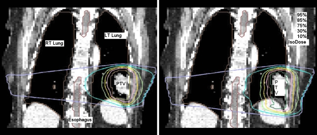
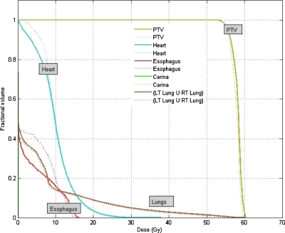
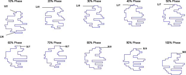
The resultant dose distributions and the corresponding dose-volume histograms (DVHs) of the lung cancer case are presented in Figs. 34, respectively. In Fig. 3, the isodose lines (95%, 85%, 75%, 30%, and 10%) for the cumulative dose of the 4D VMAT plan is plotted on the left panel as compared to the 3D VMAT plan on the right panel. It is observed that in the case of 4D VMAT plan, the 95% isodose line conforms tightly around the PTV. This conformality results from the fact that the treatment beam is tracking the target’s motion in the SI direction while the gantry is rotating around the patient. The dose is effectively delivered to the target while avoiding irradiation of the surrounding regions. In the case of 3D VMAT, the PTV is defined as the union of the target at all phases and thus is an elongated region in SI direction leading to isodose lines that are elongated. As a result, the OARs and other regions receive more dose than in the 4D VMAT plan. The DVHs in Fig. 4 show that although the PTV achieves similar coverage, the heart and esophagus receive a less dose by using the 4D VMAT. The percentage volumes of heart that receives 5 Gy or more (V5) are 85% for 4D planning versus 95% for 3D planning. The V5 values for esophagus are 24% for 4D planning versus 40% for 3D planning. The conformity index (CI) is 1.38 for 4D planning versus 1.41 for 3D planning (Table 1). Figure 5 shows the resultant apertures for ten consecutive control points covering a full duty cycle for the 4D planning of the lung case. The first aperture represents the optimized segment shape at 0° of the gantry angle (i.e., 10% phase as shown in Fig. 5).
Figure 3.
Dose distribution for the lung case. 4D VMAT (left) versus 3D VMAT (right).
Figure 4.
DVHs for the lung case. The solid and dotted lines represent the results of 4D VMAT planning and 3D VMAT planning, respectively.
Table 1.
Summary of the lung IMRT plan statistics for the 4D and 3D planning. In this table, V5 are defined as percentage volume that receives 5 Gy or more dose. Conformity index is defined as the ratio of volume of reference isodose (95% isodose) and target volume.
| Lung | 4D VMAT | 3D VMAT |
|---|---|---|
| GTV mean dose | 58 Gy | 58 Gy |
| GTV dose std | 2.5 Gy | 2.5 Gy |
| GTV D90 | 95.1% | 95.0% |
| Esophagus V5 | 24% | 40% |
| Heart V5 | 85% | 95% |
| Conformity index | 1.38 | 1.41 |
Figure 5.
Resultant apertures for ten consecutive control points for the lung case. The leaf index is indicated by the label. R19 indicates the 19th leaf on the right bank, for example.
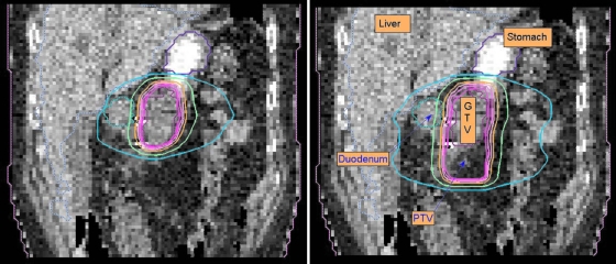
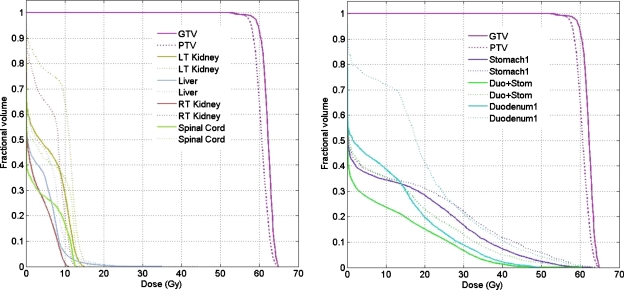
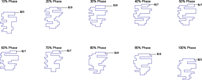
The resultant dose distributions and the corresponding DVHs of the pancreas cancer case are presented in Figs. 67, respectively. In Fig. 6, the isodose lines (95%, 90%, 80%, 50%, and 10%) for the accumulative dose of 4D VMAT plan is plotted on the left panel as compared to the 3D VMAT plan (right). It is observed that in the case of 4D VMAT planning the 95% isodose line conforms very well the ITV, because the treatment beam tracks the target motion while the gantry is rotating around the patient. The dose is effectively delivered to the target while avoiding the irradiating of the surrounding region. In 3D plan, the isodose lines are elongated and OARs and other regions receive more dose than that of 4D VMAT plan. The DVHs in Fig. 7 shows that although the PTV achieves similar coverage, the kidneys, liver, stomach, and duodenum receive much less dose by using the 4D VMAT. The percentage volumes of duodenum that receives 20 Gy or more (V20) are 20% for 4D planning versus 41% for 3D planning. The V20 values for stomach are 28% for 4D planning versus 31% for 3D planning. The CI is 1.24 for 4D planning versus 1.37 for 3D planning (Table 2). The resultant apertures for ten consecutive control points covering a full duty cycle is shown in Fig. 8 for the 4D planning of the pancreas case. The first aperture represents the optimized segment shape at 0° of gantry angle (i.e., 10% phase as shown in Fig. 8).
Figure 6.
Dose distribution for the pancreas case. 4D and 3D VMAT plans are shown in the left and right panels, respectively. In these figures, isodose lines (95%, 90%, 80%, 50%, and 10%) are plotted.
Figure 7.
DVHs for the pancreas case. The solid and dotted lines represent the results of 4D VMAT planning and 3D VMAT planning, respectively.
Table 2.
Summary of the pancreas IMRT plan statistics for the 4D and 3D planning. In this table, V20 is defined as percentage volume that receives 20 Gy or more dose. Conformity index is defined as the ratio of volume of reference isodose (95% isodose) and target volume.
| Pancreas | 4D VMAT | 3D VMAT |
|---|---|---|
| GTV mean dose | 60 Gy | 62 Gy |
| GTV dose std | 2.9 Gy | 2.9 Gy |
| GTV D90 | 98.0% | 98.0% |
| Stomach V20 | 28% | 31% |
| Duodenum V20 | 20% | 41% |
| Conformity index | 1.24 | 1.37 |
Figure 8.
Resultant apertures for ten consecutive control points for the pancreas case. The leaf index is indicated by the label. R19 indicates the 19th leaf on the right bank, for example.
In this work, we have presented a feasibility study of 4D VMAT inverse planning and demonstrated the potential benefit of the modality. For simplicity, we have only studied the ideal situation where the breathing motion is regular. In practice, this sets the theoretical limit of the dosimetric gain against 3D VMAT. Real-time monitoring of tumor motion and effective feedback of the tumor motion information plays an important role in dealing with realistic clinical situation where breathing irregularities may occur. This and issues related to the practical delivery of 4D VMAT will be a logical subject of future studies.
CONCLUSION
An inverse planning framework for 4D VMAT has been proposed to provide tempospatially optimized arc therapy plans. A significant dosimetric benefit of the 4D VMAT has been observed as compared to its 3D counterpart. 4D VMAT has the potential of reducing treatment time and producing highly conformal dose distribution.
ACKNOWLEDGMENTS
This project is supported partially by National Cancer Institute (Grant Nos. 1R01 CA98523 and CA104205), NSFC Joint Research Fund for Overseas Research Chinese, and Varian Medical Systems.
Conflicts of interest: None to disclose.
References
- Yu C. X., “Intensity-modulated arc therapy with dynamic multileaf collimation: An alternative to tomotherapy,” Phys. Med. Biol. 40(9), 1435–1449 (1995). 10.1088/0031-9155/40/9/004 [DOI] [PubMed] [Google Scholar]
- Otto K., “Volumetric modulated arc therapy: IMRT in a single gantry arc,” Med. Phys. 35(1), 310–317 (2008). 10.1118/1.2818738 [DOI] [PubMed] [Google Scholar]
- Crooks S. M., Wu X., Takita C., Matzich M., and Xing L., “Aperture modulated arc therapy,” Phys. Med. Biol. 48(10), 1333–1344 (2003). 10.1088/0031-9155/48/10/307 [DOI] [PubMed] [Google Scholar]
- Zhang P., Happersett L., Hunt M., Jackson A., Zelefsky M., and Mageras G., “Volumetric modulated arc therapy: Planning and evaluation for prostate cancer cases,” Int. J. Radiat. Oncol., Biol., Phys. 76(5), 1456–1462 (2010). 10.1016/j.ijrobp.2009.03.033 [DOI] [PubMed] [Google Scholar]
- Wong E., Chen J. Z., and Greenland J., “Intensity-modulated arc therapy simplified,” Int. J. Radiat. Oncol., Biol., Phys. 53(1), 222–235 (2002). 10.1016/S0360-3016(02)02735-9 [DOI] [PubMed] [Google Scholar]
- Ma Y., Popple R., Suh T. S., and Xing L., “Beam’s-eye-view dosimetrics-guided inverse planning for aperture-modulated arc therapy,” Int. J. Radiat. Oncol., Biol., Phys. 75(5), 1587–1595 (2009). 10.1016/j.ijrobp.2009.05.003 [DOI] [PubMed] [Google Scholar]
- Bedford J. L., “Treatment planning for volumetric modulated arc therapy,” Med. Phys. 36(11), 5128–5138 (2009). 10.1118/1.3240488 [DOI] [PubMed] [Google Scholar]
- Zygmanski P., Hogele W., Cormack R., Chin L., and Loschel R., “A volumetric-modulated arc therapy using sub-conformal dynamic arc with a monotonic dynamic multileaf collimator modulation,” Phys. Med. Biol. 53(22), 6395–6417 (2008). 10.1088/0031-9155/53/22/009 [DOI] [PubMed] [Google Scholar]
- Zhang P., Happersett L., Yang Y., Yamada Y., Mageras G., and Hunt M., “Optimization of collimator trajectory in volumetric modulated arc therapy: Development and evaluation for paraspinal SBRT,” Int. J. Radiat. Oncol., Biol., Phys. 77, 591–599 (2010). 10.1016/j.ijrobp.2009.08.056 [DOI] [PubMed] [Google Scholar]
- Mageras G. S. and Keall P., in Image Guided and Adaptive Radiation Therapy, edited by Timmerman R. and Xing L. (Lippincott Williams and Wilkins, Baltimore, 2009), pp. 64–84. [Google Scholar]
- Langen K. M. and Jones D. T., “Organ motion and its management,” Int. J. Radiat. Oncol., Biol., Phys. 50(1), 265–278 (2001). 10.1016/S0360-3016(01)01453-5 [DOI] [PubMed] [Google Scholar]
- Xing L., Lee L., and Timmerman R., in Image Guided and Adaptive Radiation Therapy, edited by Timmerman R. and Xing L. (Lippincott Williams and Wilkins, Baltimore, 2009), pp. 16–40. [Google Scholar]
- Kubo H. D., Len P. M., Minohara S., and Mostafavi H., “Breathing-synchronized radiotherapy program at the University of California Davis Cancer Center,” Med. Phys. 27(2), 346–346 (2000). 10.1118/1.598837 [DOI] [PubMed] [Google Scholar]
- Mageras G. S. and Yorke E., “Deep inspiration breath hold and respiratory gating strategies for reducing organ motion in radiation treatment,” Semin. Radiat. Oncol. 14(1), 65–75 (2004). 10.1053/j.semradonc.2003.10.009 [DOI] [PubMed] [Google Scholar]
- Wink N., Chao M., Antony J., and Xing L., “Individualized gating windows based on four-dimensional CT information for respiration gated radiotherapy,” Phys. Med. Biol. 53, 165–174 (2008). 10.1088/0031-9155/53/1/011 [DOI] [PubMed] [Google Scholar]
- Trofimov A., Rietzel E., Lu H. M., Martin B., Jiang S., Chen G. T., and Bortfeld T., “Temporo-spatial IMRT optimization: Concepts, implementation and initial results,” Phys. Med. Biol. 50(12), 2779–2798 (2005). 10.1088/0031-9155/50/12/004 [DOI] [PubMed] [Google Scholar]
- Suh Y., Weiss E., Zhong H., Fatyga M., Siebers J. V., and Keall P. J., “A deliverable four-dimensional intensity-modulated radiation therapy-planning method for dynamic multileaf collimator tumor tracking delivery,” Int. J. Radiat. Oncol., Biol., Phys. 71(5), 1526–1536 (2008). 10.1016/j.ijrobp.2008.04.018 [DOI] [PMC free article] [PubMed] [Google Scholar]
- Lee L., Ma Y., Ye Y., and Xing L., “Conceptual formulation on four-dimensional inverse planning for intensity modulated radiation therapy,” Phys. Med. Biol. 54(13), N255–N266 (2009). 10.1088/0031-9155/54/13/N01 [DOI] [PubMed] [Google Scholar]
- Ma Y., Lee L., Keshet O., Keall P., and Xing L., “Four-dimensional inverse treatment planning with inclusion of implanted fiducials in IMRT segmented fields,” Med. Phys. 36(6), 2215–2221 (2009). 10.1118/1.3121425 [DOI] [PMC free article] [PubMed] [Google Scholar]
- Pugachev A. and Xing L., “Pseudo beam’s-eye-view as applied to beam orientation selection in intensity-modulated radiation therapy,” Int. J. Radiat. Oncol., Biol., Phys. 51(5), 1361–1370 (2001). 10.1016/S0360-3016(01)01736-9 [DOI] [PubMed] [Google Scholar]
- Cotrutz C. and Xing L., “Segment-based dose optimization using a genetic algorithm,” Phys. Med. Biol. 48, 2987–2998 (2003). 10.1088/0031-9155/48/18/303 [DOI] [PubMed] [Google Scholar]
- Lujan A. E., Larsen E. W., Balter J. M., and Ten Haken R. K., “A method for incorporating organ motion due to breathing into 3D dose calculations,” Med. Phys. 26(5), 715–720 (1999). 10.1118/1.598577 [DOI] [PubMed] [Google Scholar]
- Lujan A. E., Balter J. M., and Ten Haken R. K., “A method for incorporating organ motion due to breathing into 3D dose calculations in the liver: Sensitivity to variations in motion,” Med. Phys. 30(10), 2643–2649 (2003). 10.1118/1.1609057 [DOI] [PubMed] [Google Scholar]
- Davies S. C., Hill A. L., Holmes R. B., Halliwell M., and Jackson P. C., “Ultrasound quantitation of respiratory organ motion in the upper abdomen,” Br. J. Radiol. 67(803), 1096–1102 (1994). 10.1259/0007-1285-67-803-1096 [DOI] [PubMed] [Google Scholar]
- Kawrakow I. and Fippel M., “VMC++, a MC algorithm optimized for electron and photon beam dose calculations for RTP,” in Proceedings of the 22nd Annual International Conference of the IEEE Engineering in Medicine and Biology Society, Piscataway, NJ, 2000.
- Kawrakow I., “VMC++, electron and photon Monte Carlo calculations optimized for radiation treatment planning,” in Advanced Monte Carlo for Radiation Physics, Particle Transport Simulation and Applications: Proceedings of the Monte Carlo 2000 Meeting, Lisbon, Portugal, edited by Kling A., Barao F., Nakagawa M., Távora L., and Vaz P. (Springer, Berlin, 2001), pp. 229–238.


