Abstract
Purpose: To develop a binary image reconstruction method for the autolocalization of metallic object(s) in CT with sparse projections.
Methods: The authors divide the system into two types of contents: Metal(s) and nonmetal(s). The boundaries of metallic objects are obtained by using a penalized weighted least-squares algorithm with the adequate intensity gradient-controlled. A novel mechanism of “amplifying” the difference between metal(s) and nonmetallic substances is introduced by preprocessing the sinogram data, which is shown to be necessary in dealing with a case with sparse projection data. A series of experimental studies are performed to evaluate the proposed approach.
Results: A novel binary CT image reconstruction formalism is established for the autodetermination of the shape and location of metallic objects in the presence of limited number of projections. Experimental studies reveal that the presented algorithm works well even when the embedded metal object(s) has different shape(s). It is also shown that when the projection data are sparse, a differential manipulation of projection data can greatly facilitate the binary reconstruction process and allow the authors to obtain accurate binary CT images that would otherwise be unattainable.
Conclusions: Binary CT reconstruction provides a viable method for determining the geometric distribution information of the implanted metal objects in CT imaging.
Keywords: CT, metal artifacts, sparse projections, iterative method, image reconstruction
INTRODUCTION
The presence of metals in patients may cause streaking artifacts in x-ray CT,1, 2, 3 which has long been recognized as a problem that not only limits the quality of CT images, but also makes dose calculation in radiation therapy planning problematic. In the past three decades, numerous methods have been published to reduce the metal artifacts,1, 2, 3, 4, 5, 6 but a practical solution applicable in all clinical situations remains illusive. A critical step in these methods is to identify the shape and location of metals in either image space or projection space.
In general, finding the shape and location of metal objects and determining the remaining density distribution can be considered as two different, separate problems because of their dramatically different mathematical properties. The former can be formulated as a problem of binary image reconstruction with the pixels occupied by metal to be unity and the rest of the pixels zero. The binary image reconstruction for convex shaped metals has, generally, an exact solution, which can be utilized as prior knowledge in the second reconstruction problem of determining the tissue density distribution of the remaining part. The importance of metal object extraction is threefold: (1) It represents the first and necessary step in CT metal artifact removal; (2) it presents a viable technique for metal object localization with sparse projection data; and (3) it has practical implications (even without obtaining the detailed images) in a number of clinical applications, such as dose reconstruction in brachytherapy and seeds implantation.
In this work, we propose a novel sinogram preprocessing technique and a binary image reconstruction algorithm for the identification of the metal objects from either full or sparse projections. Instead of developing a full-fledged iterative algorithm to obtain the tissue and metal density distribution simultaneously, we aim to obtain a binary image of the patient, such that the high density metals possess a “density” 1 and the remaining regions 0 with any anatomic detail ignored. For this purpose, the projection data or sinogram is first manipulated numerically, such that the difference of intensities of the projections passing and nonpassing metal(s) is enhanced. An edge-preserving iterative algorithm7, 8, 9, 10, 11 is then applied to obtain the binary image based on the preprocessed projection data. It is shown that the proposed binary reconstruction works well even when the number of projections is sparse and∕or the metal(s) is of different shape(s). The obtained geometric information of the metal objects is by itself valuable for many clinical applications, such as providing real-time image guidance during a dose delivery process with the use of implanted fiducial markers and post-therapy evaluation in permanent seeds implant based brachytherapy. The binary image information will also be indispensable to provide critical prior information for future development of artifact-free CT imaging in the future.
MATERIAL AND METHODS
In the presence of a metal object, the linear attenuation coefficient (LAC) at the boundary of the metal changes suddenly and the detection of the metal boundary is equivalent to finding the edge of a signal. In other words, an image containing metal(s) can generally be divided into two prominent components with different intensity levels. Different from conventional CT reconstruction, where the focus is to derive the density distribution within the field of view, here we propose to divide the image into two different but closely related steps: (i) Binary reconstruction to localize the metal(s) and (ii) CT image reconstruction to determine the LAC distribution of the remaining tissues with the obtained binary information about the metallic objects as prior knowledge. This work is focused on solving the first problem: To develop a binary image reconstruction method for localizing the boundary between the high and low density regions with a set of CT projections, possibly sparse projection data.
Preprocessing of projection data
The performance of binary reconstruction can be greatly improved by preprocessing the projection data, especially when the number of projections is limited. Reducing the number of projections not only decreases the angular coverage of the metal object, which results in streaking artifacts, but also reduces the difference of image intensity between a metal and its adjacent tissues in the image space, which makes it difficult to localize the metal object(s). To faithfully reconstruct a binary image, it is useful to enhance the difference of the signals characterizing the metal objects and tissues (in either image space or projection space). In this work, the difference of the projections passing and nonpassing through the metal(s) is magnified in the projection space by setting
| (1) |
where pi is the line integral of projection measurements at ith projection pixel after log-transformation and α is a constant which increases the pixel intensity to its αth power. This operation is applied for all projection pixels, allowing us to more effectively differentiate the metal and tissues. Image reconstruction with the nonlinearly amplified projections makes the metal objects localization easy, especially in the presence of sparse projections.
Gradient-controlled PWLS algorithm
We use an image intensity threshold-based method to identify the metal objects based on the nonlinearly “amplified” projection data. An iterative image reconstruction algorithm based on the PWLS criterion7, 9, 10 is implemented to accomplish the goal. In this algorithm, images are reconstructed through minimizing an objective function, which consists of a data fidelity term and a regularization term. The regularization characterizes the a priori property of the system and its role is to find a sharp edge between regions with the difference of image intensities exceeding a threshold.
The difference of LACs between metal and anatomic structures is usually much larger than that between different structures. The preprocessing step, which enlarges the difference of projections passing and nonpassing metal objects in the projection domain, leads to images more close to binary form.
The idea behind the method is that regularization is only applied for the neighbors of which the gradient is smaller than the preselected threshold. By setting a proper gradient threshold, the regularization term is applied within the metal objects or normal tissues and the reconstructed image contains only the metal object and a background with the masked patient structure information. Mathematically, the PWLS criterion can be written as7, 12
| (2) |
The first term in the right side of Eq. 2 is the weighted least-squares criterion and symbol ′ denotes the transpose operator. is the processed projection data and μ is the vector of image intensity to be reconstructed. Note that the aim here is to find a binary solution with the metal object(s) having a higher intensity, instead of searching for the attenuation coefficient distribution. By enlarging the difference of image intensity between metal(s) and soft tissue through Eq. 1, the cost function in Eq. 2 favors the u that converges to a binary distribution. In other words, the u in Eq. 2 is not the conventional linear attenuation coefficients, but a quantity close to be binary. The dimension of is the selected number of total measured projection data and the dimension of μ is the total number of voxels in the reconstructed images. Matrix A represents the projection matrix and its element aij is the length of the intersection of projection ray i with pixelj. Σ is a diagonal matrix with ith element of, i.e., an estimate of the variance of measured pi at detector bini, which can be estimated from the measured projection data according to a mean-variance relationship of projection data.9, 10, 13 The second term in the right side of Eq. 2 is a prior constraint, where β is the parameter which controls relative contribution from the measurement and the prior constraint. The intensity map μ is estimated by minimizing the objective function 2 using the Gauss–Seidel updating strategy.
For metal boundary reconstruction, we design a special quadratic penalty term for the prior constraint in Eq. 3. The form of the penalty is expressed as
| (3) |
where
| (4) |
index j runs over all image elements in the image space, and Nj represents the set of neighbors of the jth image pixel. The parameter wij is set to 1 for the first-order neighbors and for the second-order neighbors in previous applications.9, 13 By adding the parameter cjm in front, the regularization is only applied for the neighbors of which the gradient is smaller than the thresholdδ. Since the projection data are preprocessed and the difference of intensity in image space is enhanced, the threshold δ can be set accordingly to the most distinguishable level. Generally, with higher power of amplification or more projections, the suitable value of δ tends to be larger to provide clear boundaries of metal(s) and other tissues.
Experimental studies
An anthropomorphic head phantom is first used to illustrate the performance of the presented method. There exists a cubic empty space inside of the head phantom designed for holding materials for dosimetric measurement. In this study, three different types of metallic objects embedded in a tissue equivalent bolus are placed in the space, including (1) fiducial markers made of steel, (2) a brass of triangular shape, and (3) a 1∕2 in. metal screw of hexagon shape.
The CT projection data are acquired by a Varian Acuity simulator (Varian Medical Systems, Palo Alto, CA). The tube voltage is set to 125 kVp. The x-ray tube current is set to 80 mA and the duration of the x-ray pulse at each projection view is 25 ms. The distance of source-to-axis is 100 cm and source-to-detector distance is 150 cm. The total number of projections for a full 360° rotation is 680. To test the binary image reconstruction with sparse projections, a limited number of projections are chosen uniformly in the angular space out of the total 680 projections. The dimension of each acquired projection image is397 mm×298 mm, containing1024×768 pixels. To save reconstruction time, the projection data at each projection view are downsampled by a factor of 2 and only the central 16 out of 768 projection data along the axial direction are used. The size of reconstructed image is 350×350×16 and the voxel size is0.776×0.776×0.776 mm3.
RESULTS
Head phantom with embedded fiducial markers
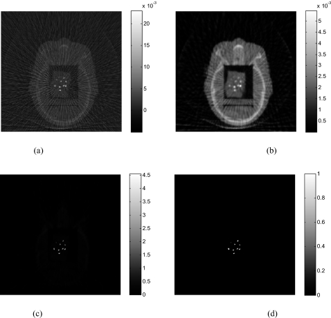
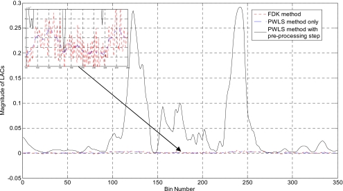
Figure 1 illustrates the results with ten ball bearings (BBs) inserted in the head phantom. Sixty-two projections are used to reconstruct the image. The FDK algorithm [Fig. 1a] exhibits strong artifacts caused by the BBs, which blurs the image and makes the identification of the BBs difficult. As is well known, FDK result is problematic even when the number of projections is not sparse (i.e., satisfying the classical Shannon–Nyquist requirement). Figure 1b shows the image reconstructed by the PWLS algorithm without preprocessing the projection data(δ=0.01). Reduced, as compared to the FDK results, but still severe artifacts are observed in the image. The image reconstructed using the proposed method (α=4andδ=1.1) is shown in Fig. 1c. Ten BBs are clearly identified with the structure of the head as background. Preprocessing the sinogram enhances the difference between the projections passing and nonpassing through the metal(s) and the choice of the threshold δ becomes much easier to locate the metal objects. The reconstructed BBs appear in different sizes in Fig. 1c because they are not placed exactly on the same image plane. Figure 1d is the reconstructed binary image of the phantom. In Fig. 2, 1D profiles extracted from the reconstructed image using different methods are plotted, providing useful insights into the benefit of the proposed sinogram preprocessing method. As can be seen, the PWLS method smoothes the nonmetallic objects while keeping a sharp edge between BBs and tissues. However, the intensity difference between projections passing and nonpassing the metal does not change much. The inset in upper-left corner of Fig. 2 is a zoomed-in picture of Fig. 2, which illustrates that the PWLS method smoothes out the nonmetallic objects in the FDK reconstruction. From Figs. 12, it is clear that preprocessing of the projection data greatly facilitates the localization of the metals.
Figure 1.
The head phantom with BBs reconstructed using 62 projections: (a) FDK algorithm; (b) PWLS algorithm without preprocessing of the projections; (c) the proposed algorithm (α=4). The binary image extracted from (c) is shown in (d).
Figure 2.
1D profiles along the horizontal midlines of images in Figs. 1a, 1b, 1c. The inset shown in the upper-left corner is a zoomed-in image of the original 1D profiles.
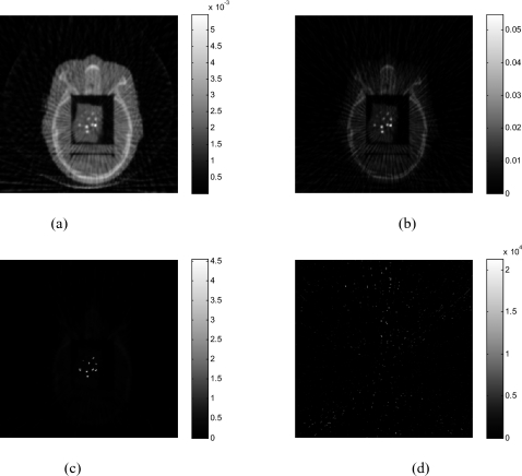
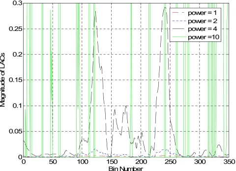
Figure 3 shows the effect of parameter α on the reconstructed images. The image obtained without preprocessing the projection data is shown in Fig. 3a(α=1). The resulting image is improved as the value of α increases. Whenα=4, the metal objects are clearly seen in the reconstructed image with little artifacts. However, the value of α should not be increased unlimited. Figure 3d indicates that whenα=10, the image is totally destroyed by the overamplification of the difference between the projections passing and nonpassing through the metals. The 1D profile along the horizontal midlines of those images (Fig. 3) is plotted in Fig. 4. The metal-tissue contrast is increased as α increases. The solid line in Fig. 4 represents the situation ofα=10, illustrating that the algorithm fails to faithfully reconstruct the image.
Figure 3.
The head phantom with BBs reconstructed using 62 projections. (a) α=1; (b) α=2; (c) α=4; (d) α=10.
Figure 4.
The 1D profile along the horizontal midline in images shown in Fig. 3.
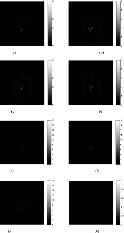
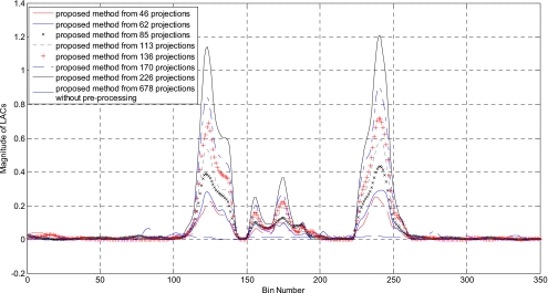
Figure 5 demonstrates the gradual improvement of the resultant image quality as the number of projection takes 46, 62, 85, 113, 136, 170, and 226, respectively(α=4). The image reconstructed with the proposed method without preprocessing from 678 projections is provided in Fig. 5h. In Fig. 6, 1D profiles along the horizontal midlines of those images are plotted to illustrate the gradual improvement. As the projection number increases, the metal-tissue contrast increases, though the intensity of the adjacent tissues is also scaled up slightly.
Figure 5.
(a) Head phantom with embedded BBs reconstructed using 46 projections; (b) 62 projections; (c) 85 projections; (d) 113 projections; (e) 136 projections; (f) 170 projections; (g) 226 projections. The image reconstructed by proposed method without preprocessing from 678 projections is displayed in (h).
Figure 6.
The 1D profiles along the horizontal midline for the images shown in Fig. 5.
Head phantom with triangularly shaped brass insert
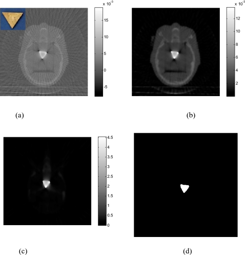
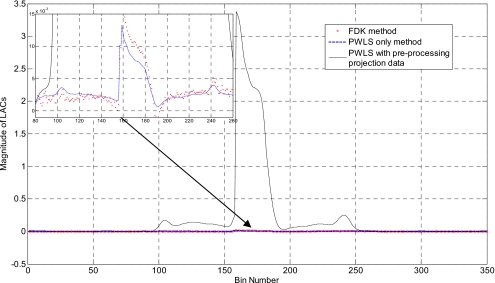
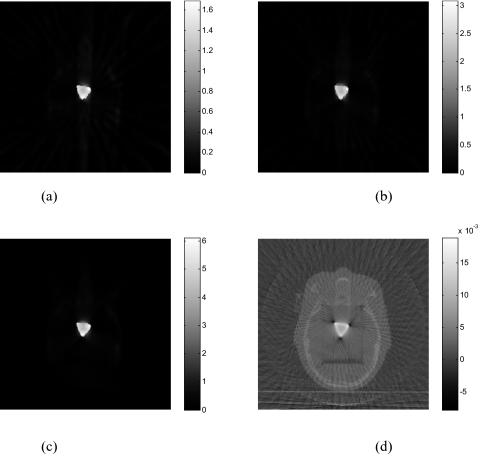
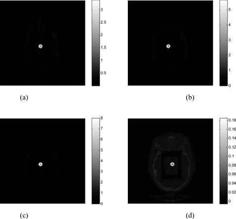
Results of the head phantom embedded with a triangularly shaped brass are shown in Fig. 7 [the upper-left corner of Fig. 7a shows the inserted triangle brass]. The number of projections used for reconstruction is only 76. In the FDK-reconstructed image [Fig. 7a], severe artifacts surrounding the brass are observed and the brass shape in the reconstructed image is geometrically distorted. The image reconstructed using the gradient-controlled PWLS algorithm (β=109andδ=0.01) and the proposed method (α=4and δ=1.3) are shown in Figs. 7b, 7c, respectively. Figure 7d shows the binary image extracted from Fig. 7c through thresholding. The rough edge of the object in the reconstructed image is a true reflection of the uneven boundaries of the triangular brass. In Fig. 8, the 1D profiles extracted from the images in Fig. 7 illustrate that sinogram preprocessing can enhance the contrast between the metal and tissue in image space.
Figure 7.
The head phantom with brass reconstructed using 76 projections: (a) FDK algorithm; (b) PWLS algorithm without sinogram preprocessing; (c) the proposed algorithm. The binary image extracted from (c) in shown in (d). The inset in (a) shows the brass.
Figure 8.
1D profiles along the horizontal midlines of images shown in Figs. 7a, 7b, 7c. Upper-left corner: Zoomed-in picture of the original image in the denoted part.
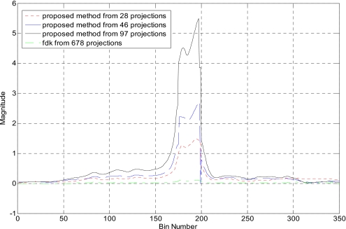
Figure 9 shows the reconstructed image of the same phantom with 28, 46, and 97 projections using the proposed method. The FDK reconstruction using 678 projections is displayed in Fig. 9d for comparison. As can be seen, the streaking artifacts are reduced when more projections are used. Figure 10 shows 1D profiles along the horizontal midlines of images in Fig. 9, which indicates that the proposed method clearly enlarges the intensity difference between metal and tissues as compared to FDK method.
Figure 9.
Head phantom with brass from (a) 28, (b) 46, and (c) 97 projections. The FDK-reconstructed image using 678 projections is provided in (d).
Figure 10.
1D profile along the horizontal midline of the reconstructed images in Fig. 9.
Head phantom with metal screw inserted
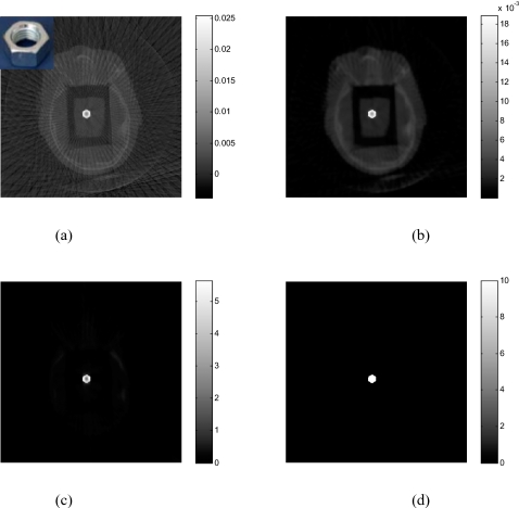
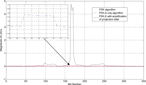
Figure 11a shows an FDK-reconstructed image of the head phantom with a 1∕2 in. screw inserted. The images obtained using PWLS with and without sinogram preprocessing are shown in Figs. 11b, 11c. Here we use 76 projections with amplificationα=4. Severe streaking artifacts appear in the FDK algorithm. The PWLS algorithm smoothes these artifacts, but the edge of the metal is still blurred by the surrounding tissues [Fig. 11b]. With preprocessing of the projection data, the edge of the screw is sharpened in Fig. 11c. The binary image extracted [Fig. 11d] accurately localizes the metal screw. The 1D profiles along the horizontal midlines of the images in Fig. 11 are plotted in Fig. 12.
Figure 11.
(a) The head phantom with metal screw inserted reconstructed using 76 projections by FDK algorithm; (b) PWLS algorithm without preprocessing projection data; (c) PWLS combined with preprocessing projection data. The binary image extracted from (c) is shown in (d). The inset in (a) shows the 1∕2 in. screw.
Figure 12.
1D profiles along the horizontal midline of images in Fig. 11. The inset is the zoomed-in plot around the metal.
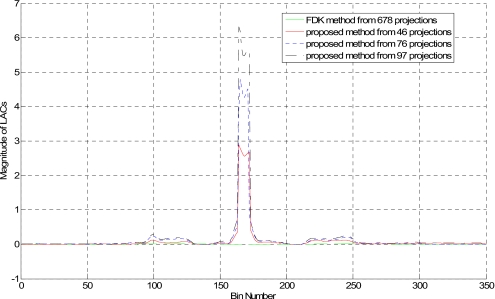
Figure 13 shows the reconstructed images by the proposed method using 46, 76, and 97 projections, along with the FDK-reconstructed image using 678 projections. Even though only 46 projections are used, the binary image [Fig. 13d] delineates the metal much clearer than that of FDK reconstruction [Fig. 13d]. Figure 14 shows the 1D profiles along the horizontal midlines in images in Fig. 13.
Figure 13.
Reconstructed images of metal screw using proposed method from different projection numbers: (a) 46 projections; (b) 76 projections; (c) 97 projections. (d) Using FDK method from 678 projections.
Figure 14.
1D profiles along the horizontal midline passing through the metal screw shown in images of Fig. 13.
DISCUSSION AND CONCLUSION
An effective technique has been described for accurate localization of metal objects in CT. The proposed metal localization technique involves two novelties: (i) Preprocessing the sinogram to enhance the contrast between the metal and adjacent tissues and (ii) gradient-controlled PWLS criterion to extract binary image information. In this work, we modify the projection data by adjusting the value of the parameter α in Eq. 1, which is quite natural because for any two projections p1>1 andp2>1, a value of α>1 will enlarge the difference between them, i.e., . It would be interesting to consider other sinogram preprocessing methods to achieve the same goal.
An interplay exists between the number of projections and the sinogram modification parameterα. In general, the image quality improves (less streaking artifacts and enhanced contrast between the metal and tissue) as the number of projection increases. The search of the metal boundary using the PWLS algorithm is facilitated by the enhanced metal-tissue contrast. In principle, any edge-preserving iterative method is applicable to solve the binary problem here. The PWLS is chosen because of its demonstrated ability in this type of applications.9 When the projection data are sparse, the metal-tissue contrast is dramatically reduced, making the metal localization intractable. The situation can be compensated by preprocessing the sinogram to enlarge the difference between the projections passing and nonpassing the metal(s). We found that the preprocessing of sinogram is necessary for cases with a small number of projections. It is important to emphasize that there is an optimal range of the parameterα. The interplay between the nonlinear modification of the sinogram and the number of projections is an interesting subject of study in the future for better understanding their influence on the reconstruction results individually and jointly.
Metal objects localization with sparse projections has many potential applications,14, 15, 16, 17 especially in 4D cone beam CT (CBCT) imaging.18, 19, 20, 21 When onboard CBCT is used for scanning the thorax or upper abdomen, motion artifacts appear in the reconstructed images due to intrascanning organ motion within the field of view. 4D CBCT or respiration-correlated CBCT technique groups the acquired projection data into several bins according to their respiratory phases and reconstructs each phase bin independently to obtain a series of volumetric images corresponding to different phases.18 In this case, since the projections are divided into several phase groups during 4D CBC imaging, the number of projections available for each phase (∼70projections) becomes much less than that in a regular 3D CBCT. The proposed method provides a natural solution for localizing the metals and for artifact removal on 4D CBCT imaging. In other applications, the use of a limited number of projections will greatly reduce the radiation dose incurred to the patients and thus lead to improved patient care.
In conclusion, a novel binary image reconstruction technique has been proposed for accurate determination of the locations and shapes of metal objects. Combining the effective preprocessing of the projection data and a gradient-controlled PWLS algorithm, the technique can readily localize implanted metal objects with an accuracy comparable with CT pixel size. Given the widespread clinical use of CT∕CBCT imaging, the proposed method should have practical implications in diagnostics and image guided interventions through more accurate localization of the implanted∕embedded metal objects and, in the future, possible artifact-free CT image reconstruction with effective use of extracted binary information.
ACKNOWLEDGMENTS
This project was supported in part by grants from the National Science Foundation (Grant No. 0854492), the National Cancer Institute (Grant No. R01CA104205), and the Department of Defense (Grant No. W81XWH-08-1-0127).
References
- Robertson D. D., Yuan J., Wang G., and Vannier M. W., “Total hip prosthesis metal-artifact suppression using iterative deblurring reconstruction,” J. Comput. Assist. Tomogr. 21(2), 293–298 (1997). 10.1097/00004728-199703000-00024 [DOI] [PubMed] [Google Scholar]
- Kalender W. A., Hebel R., and Ebersberger J., “Reduction of CT artifacts caused by metallic implants,” Radiology 164(2), 576–577 (1987). [DOI] [PubMed] [Google Scholar]
- Veldkamp W. J., Joemai R. M., van der Molen A. J., and Geleijns J., “Development and validation of segmentation and interpolation techniques in sinograms for metal artifact suppression in CT,” Med. Phys. 37(2), 620–628 (2010). 10.1118/1.3276777 [DOI] [PubMed] [Google Scholar]
- Prell D., Kyriakou Y., Struffert T., Dorfler A., and Kalender W. A., “Metal artifact reduction for clipping and coiling in interventional C-arm CT,” AJNR Am. J. Neuroradiol. 31(4), 634–639 (2009). 10.3174/ajnr.A1883 [DOI] [PMC free article] [PubMed] [Google Scholar]
- Liu J. J. and Lutkin J. E., “Imaging of patients having metal implant using x-ray computed tomography,” J. X-Ray Sci. Technol. 17(4), 355–365 (2009). [DOI] [PubMed] [Google Scholar]
- Bal M. and Spies L., “Metal artifact reduction in CT using tissue-class modeling and adaptive prefiltering,” Med. Phys. 33(8), 2852–2859 (2006). 10.1118/1.2218062 [DOI] [PubMed] [Google Scholar]
- Fessler J. A., “Penalized weighted least-squares image-reconstruction for positron emission tomography,” IEEE Trans. Med. Imaging 13(2), 290–300 (1994). 10.1109/42.293921 [DOI] [PubMed] [Google Scholar]
- Li T. F., Li X., Wang J., Wen J. H., Lu H. B., Hsieh J., and Liang Z. R., “Nonlinear sinogram smoothing for low-dose x-ray CT,” IEEE Trans. Nucl. Sci. 51(5), 2505–2513 (2004). 10.1109/TNS.2004.834824 [DOI] [Google Scholar]
- Wang J., Li T., and Xing L., “Iterative image reconstruction for CBCT using edge-preserving prior,” Med. Phys. 36(1), 252–260 (2009). 10.1118/1.3036112 [DOI] [PMC free article] [PubMed] [Google Scholar]
- Zhu L., Wang J., and Xing L., “Noise suppression in scatter correction for cone-beam CT,” Med. Phys. 36(3), 741–752 (2009). 10.1118/1.3063001 [DOI] [PMC free article] [PubMed] [Google Scholar]
- La Rivière P. J., “Penalized-likelihood sinogram smoothing for low-dose CT,” Med. Phys. 32(6), 1676–1683 (2005). 10.1118/1.1915015 [DOI] [PubMed] [Google Scholar]
- Wang J., Li T., Lu H. B., and Liang Z. R., “Penalized weighted least-squares approach to sinogram noise reduction and image reconstruction for low-dose x-ray computed tomography,” IEEE Trans. Med. Imaging 25(10), 1272–1283 (2006). 10.1109/TMI.2006.882141 [DOI] [PMC free article] [PubMed] [Google Scholar]
- Wang J., Li T., Liang Z., and Xing L., “Dose reduction for kilovotage cone-beam computed tomography in radiation therapy,” Phys. Med. Biol. 53(11), 2897–2909 (2008). 10.1088/0031-9155/53/11/009 [DOI] [PubMed] [Google Scholar]
- Stradiotti P., Curti A., Castellazzi G., and Zerbi A., “Metal-related artifacts in instrumented spine. Techniques for reducing artifacts in CT and MRI: State of the art,” Eur. Spine J. 18, 102–108 (2009). 10.1007/s00586-009-0998-5 [DOI] [PMC free article] [PubMed] [Google Scholar]
- Xia D., Roeske J. C., Yu L., Pelizzari C. A., Mundt A. J., and Pan X., “A hybrid approach to reducing computed tomography metal artifacts in intracavitary brachytherapy,” Brachytherapy 4(1), 18–23 (2005). 10.1016/j.brachy.2004.11.001 [DOI] [PubMed] [Google Scholar]
- Roeske J. C., Lund C., Pelizzari C. A., Pan X., and Mundt A. J., “Reduction of computed tomography metal artifacts due to the Fletcher-Suit applicator in gynecology patients receiving intracavitary brachytherapy,” Brachytherapy 2(4), 207–214 (2003). 10.1016/j.brachy.2003.08.001 [DOI] [PubMed] [Google Scholar]
- De Man B., Nuyts J., Dupont P., Marchal G., and Suetens P., “Reduction of metal streak artifacts in x-ray computed tomography using a transmission maximum a posteriori algorithm,” in IEEE Nuclear Science Symposium Conference Record, 1999, Vol. 2, pp. 850–854.
- Sonke J. J., Zijp L., Remeijer P., and van Herk M., “Respiratory correlated cone beam CT,” Med. Phys. 32(4), 1176–1186 (2005). 10.1118/1.1869074 [DOI] [PubMed] [Google Scholar]
- Li T., Xing L., McGuinness C., Munro P., Loo B., and Koong A., “Four-dimensional cone-beam CT using an on-board imager,” Med. Phys. 33, 3825–3833 (2006). 10.1118/1.2349692 [DOI] [PubMed] [Google Scholar]
- Li T. and Xing L., “Optimizing 4D cone-beam CT acquisition protocol for external beam radiotherapy,” Int. J. Radiat. Oncol., Biol., Phys. 67(4), 1211–1219 (2007). 10.1016/j.ijrobp.2006.10.024 [DOI] [PubMed] [Google Scholar]
- Lu J., Guerrero T. M., Munro P., Jeung A., Chi P. C., Balter P., Zhu X. R., Mohan R., and Pan T., “Four-dimensional cone beam CT with adaptive gantry rotation and adaptive data sampling,” Med. Phys. 34(9), 3520–3529 (2007). 10.1118/1.2767145 [DOI] [PubMed] [Google Scholar]


