Abstract
Higher complication rates and lower survivorship are still seen for total elbow arthroplasties compared to total knee and hip arthroplasties. This is partly due to polyethylene wear of the articular surface induced by excessive articular contact stress during elbow motion. The aim of this study was to dynamically evaluate in vivo three-dimensional elbow motion after total elbow arthroplasty. Twelve patients (15 elbows) who underwent operation with the Osaka University Model Total Elbow System were analysed using X-ray fluoroscopic imaging and a two-dimensional/three-dimensional registration technique, which could accurately estimate the three-dimensional spatial position of components. Valgus/varus angle and rotation between humeral and ulnar components showed wide variations among patients. Elbows with valgus angle and internal rotation >10° could induce edge-loading of the articular surface. Component alignment, articular configuration, and soft-tissue balance can affect the kinematics of total elbow arthroplasty.
Introduction
Total elbow arthroplasty (TEA) is one surgical treatment option for painful destruction of the elbow joint due to rheumatoid arthritis. With the introduction of linked semi-constrained TEA and non-linked resurfacing TEA, favourable mid- and long-term outcomes have been reported [1–8]. However, compared with total knee and total hip arthroplasties, survivorship remains lower and complication rates are higher [9, 10]. With a loose-hinged articular surface, linked semi-constrained TEAs can compensate for soft-tissue imbalance and are thought to recreate physiological joint kinematics. Conversely, given the nature of hinged joints, wear and breakage of the polyethylene bush may occur due to excessive rotational torque during flexion/extension of the elbow joint resulting from positioning-alignment of components [11]. As for non-linked resurfacing TEAs, although no problem is seen with the polyethylene bush, dislocation or subluxation is a matter of concern. To avoid post-operative instability, resurfacing TEAs are designed to have relatively high intrinsic constraint that is determined by the articular configuration of engaging humeral and ulnar components. However, when soft-tissue imbalance exceeds the intrinsic constraints of the prosthesis, edge loading or line contact between components may occur, leading to excessive polyethylene wear. Furthermore, a common problem with both semi-constrained and resurfacing TEAs is high contact stress at the prosthesis–cement interface or prosthesis–bone interface, resulting from indirect articular rotational torque that can induce early aseptic loosening. To predict the likelihood of polyethylene wear and aseptic loosening, detection of soft tissue imbalances by dynamic evaluation is very important. However, with regard to resurfacing TEAs, detailed articular kinematics during flexion/extension have never been reported. One reason for this lack of information may be the absence of suitable techniques for dynamic analyses. We have reported in vivo three-dimensional (3D) kinematics for total knee arthroplasty using kinematic analysis techniques from single-view X-ray images, such as the ‘2D/3D registration technique’ [12]. Using this technique, we found that differences in articular design and surgical technique can lead to vastly different kinematics [12–14]. The unknown in vivo articular kinematics of resurfacing TEA should be amenable to analysis using this approach.
The purpose of this study was thus to dynamically evaluate elbow motion after TEA by 3D analysis of in vivo kinematics between humeral and ulnar components.
Patients and methods
Patients
Between October 1997 and September 2006, 51 patients (57 elbows) who suffered from rheumatoid arthritis underwent surgery at our institute using the Osaka University Model Total Elbow System (OU-Elbow; Finsbury Orthopaedics, Surrey, UK) (Fig. 1). Of these, 12 consecutive patients (15 elbows) who agreed to participate in the investigation were included in the study (Table 1). All study protocols were approved by the institutional review board. One senior author (T.T.) performed all TEA procedures. One patient was male (two elbows) and eleven were female (13 elbows). Mean age at the time of surgery was 57.3 years (range, 42–64 years). Mean duration between operation and fluoroscopic surveillance was 36.7 months (range, 3–117 months). Pre-operative plain radiography showed that two elbows were Larsen grade III, nine were grade IV, and two were grade V. According to the Mayo Elbow Performance Index (MEPI) [15], eight elbows were excellent and seven elbows were good (Table 1).
Fig. 1.
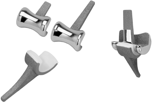
Osaka University Model Total Elbow System (OU-Elbow). This prosthesis is a non-linked type without a radial head component. Each component is designed to align 5° valgus to the articular surface
Table 1.
Demographic data
| Elbow | Age (years) | Gender | Follow-up (months) | Larsen grade | Mayo elbow performance index | |
|---|---|---|---|---|---|---|
| Points | Classification | |||||
| 1 | 53 | F | 117 | NA | 95 | Excellent |
| 2 | 54 | F | 3 | IV | 100 | Excellent |
| 3 | 55 | F | 12 | IV | 85 | Good |
| 4 | 55 | F | 20 | IV | 95 | Excellent |
| 5 | 64 | F | 60 | IV | 75 | Good |
| 6 | 60 | F | 56 | IV | 95 | Excellent |
| 7 | 58 | F | 35 | III | 85 | Good |
| 8 | 60 | F | 8 | IV | 100 | Excellent |
| 9 | 63 | M | 3 | V | 80 | Good |
| 10 | 63 | M | 44 | V | 85 | Good |
| 11 | 42 | F | 94 | NA | 95 | Excellent |
| 12 | 58 | F | 23 | IV | 100 | Excellent |
| 13 | 58 | F | 52 | III | 95 | Excellent |
| 14 | 63 | F | 3 | IV | 85 | Good |
| 15 | 53 | F | 21 | IV | 75 | Good |
F female, M male, NA not available
Prosthesis
The OU-Elbow, developed at our institute, is a non-linked, resurfacing type prosthesis (Fig. 1) that was first implanted in 1997. Articular surfaces of the humeral and ulnar components have constant radial geometry in the sagittal plane. The humeral component is made of cobalt-chromium alloy, with part of the stem porous-coated using a plasma spray of titanium alloy. The ulnar component is either entirely polyethylene or metal-backed with a porous-coated stem of titanium alloy. All patients in the study were treated using metal-backed components. Each component was designed to align 5° valgus to the articular surface, to reproduce physiological alignment. This prosthesis was designed to provide relatively high valgus/varus and a particularly strong rotational constraint from the concave articular geometry of the humeral component in the coronal plane.
Operative technique
All procedures were performed using a posterior approach. Medial and lateral collateral ligaments were transected and not reattached. Radial head resection was performed. Components were fixed with cement when initial fixation seemed unstable. Triceps tendon and fascial layers were sutured at 90° elbow flexion and neutral rotational position. Two elbows had humeral components fixed with cement and 11 elbows had ulnar components fixed with cement.
In vivo kinematic measurement technique
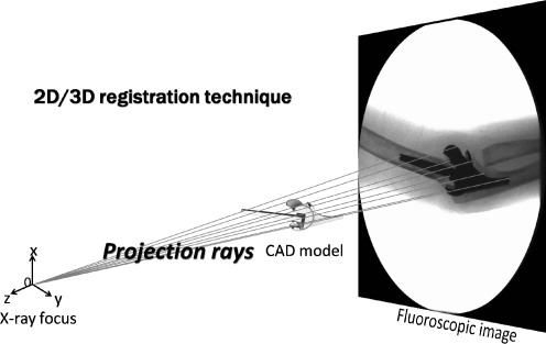
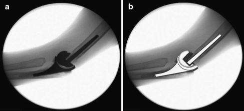
Under fluoroscopic examination in the sagittal plane, each patient was in the upright standing position and asked to bend the elbow from full extension to full flexion at a comfortable rate. Successive elbow movements were recorded as serial digital X-ray images (1024 × 1024 × 12 bits/pixels, 7.5 Hz; serial spot images saved as digital imaging and communication in medicine [DICOM] files) using a 12-inch digital image intensifier system (C-vision PRO-T; Shimadzu, Kyoto City, Japan) and 1.2–2.0-ms pulsed X-ray beams. In vivo 3D positions of the humeral and ulnar components were estimated using the two-dimensional (2D)/3D registration technique (Figs. 2 and 3) [12], which uses computer-aided design (CAD) models to reproduce spatial postures of the humeral and ulnar components from calibrated (including distortion correction) single-view fluoroscopic imaging. The registration algorithm proposed by Zuffi et al. [16] was implemented. This algorithm uses a feature-based approach to minimise distances between lines drawn from a contour found in the 2D image to the X-ray source, and a surface CAD model with iterative computations. Original validation work for the 2D/3D registration technique for TKA was performed and reported using phantom experiments [12]. An Optotrak 3020 system (Northern Digital Inc., Ontario, Canada), which is a 3D optical localiser that tracks infrared light-emitting diode (LED)-mounted markers with an accuracy of about 0.1 mm, was used to determine ‘grand-truth’ positions for comparison with the 2D/3D registration described. Root-mean-square errors of the relative position for the femoral component in the tibial component coordinate system were 0.2°, 0.6°, and 0.6° for rotation in the coronal, axial, and sagittal planes, respectively, and 0.6, 0.3, and 1.0 mm for translation perpendicular to the coronal, axial, and sagittal planes, respectively.
Fig. 2.
Scheme of 2D/3D registration technique. The 2D/3D registration technique is a 3D kinematic measurement using CAD models to reproduce spatial postures of the humeral and ulnar components from calibrated single-view fluoroscopic images. The registration algorithm utilizes a feature-based approach to minimize distances between lines drawn from a contour found on the 2D fluoroscopic image to the X-ray source and surface of the CAD model with iterative computations
Fig. 3.
An example of the 2D/3D registration technique. a Fluoroscopic image. b After registration, spatial positions of components were estimated in a 3D manner
Coordinate systems and kinematic descriptions
In each component, lateral and medial faces of the articular surfaces in the sagittal plane represented an accurate single-radius circle. The coordinate system of the humeral component was defined with the origin at the midpoint of the centres of bilateral articular surfaces, the axial plane parallel to the distal fixation interface, and the coronal and sagittal planes perpendicular to the axial plane. Similarly, the coordinate system of the ulnar component was defined with the origin at the midpoint of the centres of bilateral articular surfaces, the coronal plane parallel to the dorsal fixation interface, and the axial and sagittal planes perpendicular to the coronal plane. The X, Y and Z axes were defined as the axes perpendicular to the coronal, axial and sagittal planes, respectively. Magnitudes of rotation about the X, Y and Z axes of the ulnar component relative to the humeral component were expressed as varus/valgus, internal/external rotation, and extension/flexion, respectively, using Euler’s method. All data are expressed as mean with standard deviation (SD).
Measurement of component alignment
Using post-operative plain AP radiography, angles between the axis of the shaft of humerus and the stem of the humeral component and between the axis of the shaft of ulna bone and the stem of the ulnar component were measured using a goniometer, describing humeral alignment and ulnar alignment each. Valgus alignment was denoted as positive.
Evaluation of quasi-contact area of the articular surface
Our kinematic analysis system is able to visualise quasi-contact areas between two 3D CAD models [17]. Since position of the radiolucent polyethylene of the ulnar component can be determined from the estimated position of the ulnar component, applying this system to the results of relative positions between humeral and ulnar components allows a dynamic display of the quasi-contact area of the articular surface on the polyethylene. Wear of polyethylene was not assumed. According to the type of articular contact, all elbows were divided into one of three groups (Fig. 4):
Quasi-contact area equally distributed throughout flexion
Quasi-contact area laterally (or medially) loaded at some time during flexion
Quasi-contact area laterally (or medially) loaded throughout flexion
Nonparametric Mann-Whitney tests were used for comparisons of valgus angle, rotation, and component alignment between groups 1 and 2 and between groups 1 and 3. Values of p < 0.05 were considered statistically significant.
Fig. 4.
According to the type of articular contact with the polyethylene, each elbow was placed into one of three groups. a Group 1, during flexion, contact area was widely distributed. b Group 2, contact area was laterally edge-loaded at some time during flexion. c Group 3, contact area was laterally edge-loaded during flexion
Results
Range of motion
Between the humeral and ulnar components, mean maximum flexion was 132.1 ± 7.0°. Restriction of elbow extension was 33.5 ± 13.3° and the arc of the range of elbow flexion/extension was 98.6 ± 12.4°.
Valgus/varus angle
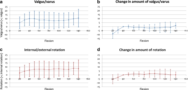
Figure 5a shows the transition of valgus/varus angle between components during flexion. Mean ± 1 SD values at any 10° of flexion are shown on the graph. Valgus angle between components was 6.3 ± 6.6° at full extension, and 7.8 ± 8.4° at full flexion. On average, valgus/varus angle between components was about 8° throughout flexion, although inter-patient variation was very large. However, from 40 to 130° of flexion, the change in amount of valgus/varus angle was very small in each elbow (1.7 ± 8.4°; Fig. 5b).
Fig. 5.
Relative valgus/varus angle and rotation between components during flexion. The horizontal scale shows flexion angle between components and the vertical scale shows valgus/varus angle and rotation. Positive values represent valgus and internal rotation. a, c Mean ± SD for valgus angles and rotation of 15 elbows. b, d Change in amount of valgus/varus angle and rotation from that at 40° flexion
Rotation
Figure 5c shows the transition of rotation between components during flexion. Internal rotation between components was 4.1 ± 6.3° at full extension and 6.9 ± 8.3° at full flexion. Mean internal rotation between components was about 7° throughout flexion, although inter-patient variation was very large. However, from 40 to 130° of flexion, change in amount of rotation was very small in each elbow (1.6 ± 2.7°, Fig. 5d).
Component AP alignment
Table 2 shows the results of AP alignment of components. Humeral alignment of all the elbows was 4.0 ± 3.9°, and ulnar alignment of all the elbows was 5.9 ± 4.3°.
Table 2.
Components’ valgus alignment into the bones
| Elbow | Humeral alignment (°) | Ulnar alignment (°) |
|---|---|---|
| 1 | 9 | 6 |
| 2 | 1 | 6 |
| 3 | 1 | 12 |
| 4 | 5 | 8 |
| 5 | 2 | 7 |
| 6 | 12 | 6 |
| 7 | 2 | 1 |
| 8 | 12 | 9 |
| 9 | 4 | −5 |
| 10 | 3 | 5 |
| 11 | 4 | 13 |
| 12 | 2 | 7 |
| 13 | 2 | 2 |
| 14 | −2 | 8 |
| 15 | 3 | 3 |
| Mean | 4.0 | 5.9 |
| SD | 3.9 | 4.3 |
Valgus alignment was denoted as positive
SD standard deviation
Quasi-contact area of polyethylene
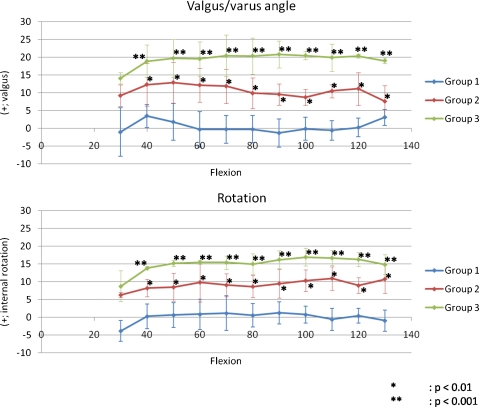
Classification was group 1 in seven of 15 elbows, group 2 in four elbows, and group 3 in four elbows. Valgus angle and internal rotation of group 1 were between −10° and 10° throughout flexion. Elbows in group 2 exhibited valgus angle or internal rotation >10° at some point during elbow flexion. Elbows in group 3 exhibited valgus and internal rotation >10° throughout flexion. All through flexion from 40 to 130°, valgus angle was significantly less in group 1 than in group 2 (p < 0.01) or group 3 (p < 0.001) and internal rotation was significantly less in group 1 than in group 2 (p < 0.01) or group 3 (p < 0.001) (Fig. 6).
Fig. 6.
Valgus/varus angles and rotation in groups 1–3 during flexion. There were six elbows in group 1, four in group 2, and four in group 3. From 40 to 130°, valgus angle was significantly less in group 1 than in group 2 (p < 0.01) or group 3 (p < 0.001) and internal rotation was significantly less in group 1 than in group 2 (p < 0.01) or group 3 (p < 0.001)
Humeral alignment in group 3 was significantly larger than that in group 1. Humeral alignment in group 2 had no significant difference compared with that in group 1. With regard to ulnar alignment, there was no significant difference between group 1 and group 2 and between group 1 and group 3 (Fig. 7).
Fig. 7.
Component alignment in group 1–3. Valgus alignment was denoted as positive. Valgus alignment in group 3 was significantly larger than in group 1 (p < 0.05). a Humeral alignment. b Ulnar alignment
Discussion
As a means of achieving in vivo 3D motion analysis of artificially replaced joints using a single-view X-ray fluoroscopic image and a computer analysis system, the 2D/3D registration technique offers several advantages over other methods of measuring relative position between humeral and ulnar components, such as the surgeon’s manual tests or 2D plain radiography. Manual tests are not objective and radiographic measurements can differ depending on patient position during X-ray examination. Both evaluation methods show critical problems in accuracy. Several reports have described kinematic evaluations of cadaver elbow joints [15, 18–24]. However, those reports used kinematic analyses of passive motion under non-physiological conditions, which may differ substantially from in vivo kinematics. Ericson et al. used radio-stereometric analysis (RSA) to examine in vivo variations in position of the elbow flexion axis after TEA with three different prostheses; they reported changes in instantaneous flexion axis between 30°, 60°, 90°, and 120° of elbow flexion that did not comprise a true successive motion analysis [25].
The 2D/3D registration technique, in which continuous joint motion can be analysed three-dimensionally by extracting silhouettes of the prosthesis from single-view fluoroscopic images and superimposing CAD models of the prosthesis components on these silhouettes, has become mainstream for motion studies after total knee arthroplasty [12–14, 26, 27]. Our institute has also developed one of the 2D/3D image-matching techniques and has investigated in vivo 3D kinematics of various types of total knee arthroplasty [12–14]. Using this technique, we can evaluate 3D relative positions between components under dynamic conditions. Furthermore, using an improved version of this technique, quasi-contact areas between components can be estimated [17].
Our study quantitatively evaluated relative positions of one of the resurfacing TEAs between humeral and ulnar components during elbow flexion from full extension to maximum flexion and visualised this motion. Relative positions between humeral and ulnar components showed extremely wide variation among patients throughout flexion. Standard deviation was sometimes >10°. Conversely, each elbow exhibited relatively constant valgus/varus angle and rotation between components from full extension to maximum flexion. That is, an elbow with large valgus angle at extension maintained that angle to maximum flexion, while an elbow with small valgus angle at extension kept that angle to maximum flexion. The same was true for rotation. We considered that the primary reason for this kinematic consistency despite large valgus angle and rotation during flexion is mal-positioning of the components in the bones. The results shown in Fig. 7 indicate that valgus alignment of the components, especially humeral alignment, can influence the kinematics. The more valgus humeral alignment, the less was the quasi-contact area of the polyethylene. The humeral valgus alignment may widely vary because of the large bone canal relative to the thin stem of the component. Surgical technique and instruments for TEA are not as well established as for TKA; therefore, it is not easy to determine valgus/varus and rotational alignment of the components intra-operatively. Mal-positioning of the components leads to loss of congruent articulation and uneven loading to the joint surface. TEA is mostly indicated for elbows destroyed by rheumatoid arthritis, which erodes not only bone and joints, but also soft tissues, including collateral ligaments. This damage to soft tissues is one of the reasons why optimising the intra-operative soft-tissue balance is difficult. Furthermore, intra-operative invasion to soft tissues, such as release of collateral ligaments and resection of the radial head, can induce further post-operative soft-tissue imbalances. However, whether such soft-tissue imbalances occur because of the surgical technique or occur over time post-operatively remains unclear and should be investigated in the future. One reason for intra-operative soft-tissue imbalance probably lies in the design of components. The prosthesis we used has one size only and the components themselves may thus be excessively bulky for individuals with small elbow joints, making accurate soft-tissue balance difficult to obtain.
Excessive valgus angle and internal rotation between components can cause edge-loading of the articular surface. In this study, each elbow was classified into three general categories according to the type of quasi-contact area of the articular surface. Elbows in group 2 that had unequally loaded kinematics and group 3 with linear contact throughout flexion showed significantly larger valgus and internal rotation. From the results of this study, valgus and rotational mal-alignment >10° can cause edge-loading of the articular surface and pose a risk for early polyethylene wear. In addition, decreased articular contact area may lead to decreased articular constraint and increased risk of dislocation and subluxation. Accurate component positioning and soft-tissue balance may reduce excessive articular contact stress and critical complications such as polyethylene wear and aseptic loosening. Achieving appropriate component positioning and accurate intra-operative soft-tissue balance is thus crucial to achieve better long-term clinical results with TEA.
In this study, component alignment was measured only from AP radiography. However, not only valgus/varus alignment but also rotational alignment can influence the mal-alignment/rotation between humerus and ulna bones, one probable cause of soft-tissue imbalance. Therefore, further study will be needed to elucidate the effects of 3D alignment and position of the components on joint kinematics.
The results of this study indicate that relative position of valgus/varus angle and rotation between components might rely on component alignment and soft-tissue balance. Development of sophisticated surgical techniques to obtain appropriate component positioning and accurate soft-tissue balance would thus allow appropriate articular congruency and lead to better post-operative clinical results.
References
- 1.Kelly EW, Coghlan J, Bell S. Five-to thirteen-year follow-up of the GSB III total elbow arthroplasty. J Shoulder Elbow Surg. 2004;13(4):434–440. doi: 10.1016/j.jse.2004.01.028. [DOI] [PubMed] [Google Scholar]
- 2.Gill DRJ, Morrey BF. The Coonrad-Morrey total elbow arthroplasty in patients who have rheumatoid arthritis. A ten to fifteen-year study. J Bone Joint Surg Am. 1998;80(9):1327–1335. doi: 10.2106/00004623-199809000-00012. [DOI] [PubMed] [Google Scholar]
- 3.Morrey BF, Adams RA. Semiconstrained arthroplasty for the treatment of rheumatoid arthritis of the elbow. J Bone Joint Surg Am. 1992;74(4):479–490. [PubMed] [Google Scholar]
- 4.Tanaka N, Kudo H, Iwano K, et al. Kudo total elbow arthroplasty in patients with rheumatoid arthritis: A long-term follow-up study. J Bone Joint Surg Am. 2001;83(10):1506–1513. doi: 10.2106/00004623-200110000-00008. [DOI] [PubMed] [Google Scholar]
- 5.Mori T, Kudo H, Iwano K, et al. Kudo type-5 total elbow arthroplasty in mutilating rheumatoid arthritis. J Bone Joint Surg Br. 2006;88(7):920–924. doi: 10.1302/0301-620X.88B7.17356. [DOI] [PubMed] [Google Scholar]
- 6.Rozing P. Souter-Strathclyde total elbow arthroplasty. A long-term follow-up study. J Bone Joint Surg Br. 2000;82(8):1129–1134. doi: 10.1302/0301-620X.82B8.10148. [DOI] [PubMed] [Google Scholar]
- 7.Ovesen J, Olsen BS, Johannsen HV, et al. Capitellocondylar total elbow replacement in late-stage rheumatoid arthritis. J Shoulder Elbow Surg. 2005;14(4):414–420. doi: 10.1016/j.jse.2004.10.010. [DOI] [PubMed] [Google Scholar]
- 8.Ewald FC, Simmons ED, Sullivan JA, et al. Capitellocondylar total elbow replacement in rheumatoid arthritis: long-term results. J Bone Joint Surg Am. 1993;75(4):498–507. doi: 10.2106/00004623-199304000-00004. [DOI] [PubMed] [Google Scholar]
- 9.Vessely MB, Whaley AL, Harmsen WS, et al. Long-term survivorship and failure modes of 1000 cemented condylar total knee arthroplasties. Clin Orthop Relat Res. 2006;452:28–34. doi: 10.1097/01.blo.0000229356.81749.11. [DOI] [PubMed] [Google Scholar]
- 10.Sathappan SS, Teicher ML, Capeci CC, et al. Clinical outcome of total hip arthroplasty using the normalized and proportionalized femoral stem with a minimum 20-year follow-up. J Arthroplasty. 2007;22(3):356–362. doi: 10.1016/j.arth.2006.04.004. [DOI] [PubMed] [Google Scholar]
- 11.Goldberg SH, Robert M, et al. Modes of wear after semiconstrained total elbow arthroplasty. J Bone Joint Surg Am. 2008;90(3):609–619. doi: 10.2106/JBJS.F.01286. [DOI] [PubMed] [Google Scholar]
- 12.Watanabe T, Yamazaki T, Sugamoto K, et al. In vivo kinematics of mobile-bearing knee arthroplasty in deep knee bending motion. J Orthop Res. 2004;22(5):1044–1049. doi: 10.1016/j.orthres.2003.12.013. [DOI] [PubMed] [Google Scholar]
- 13.Tamaki M, Tomita T, Yamazaki T, Hozack WJ, Yoshikawa H, Sugamoto K. In vivo kinematic analysis of a high-flex posterior stabilized fixed-bearing knee prosthesis in deep knee-bending motion. J Arthroplasty. 2008;23(6):879–885. doi: 10.1016/j.arth.2008.04.009. [DOI] [PubMed] [Google Scholar]
- 14.Tamaki M, Tomita T, Watanabe T, Yamazaki T, Yoshikawa H, Sugamoto K. In vivo kinematic analysis of a high-flexion, posterior-stabilized, mobile-bearing knee prosthesis in deep knee bending motion. J Arthroplasty. 2009;24(6):972–978. doi: 10.1016/j.arth.2008.06.012. [DOI] [PubMed] [Google Scholar]
- 15.O’Driscoll SW, An KN, Korinek S, et al. Kinematics of semi-constrained total elbow arthroplasty. J Bone Joint Surg Br. 1992;74(2):297–299. doi: 10.1302/0301-620X.74B2.1544973. [DOI] [PubMed] [Google Scholar]
- 16.Zuffi S, Leardini A, Catani F, et al. A model-based method for the reconstruction of total knee replacement kinematics. IEEE Trans Med Imaging. 1999;18(10):981–991. doi: 10.1109/42.811310. [DOI] [PubMed] [Google Scholar]
- 17.Yamazaki T, Watanabe T, Nakajima Y, Sugamoto K, Tomita T, Maeda D, Sahara W, Yoshikawa H, Tamura S. Visualization of femorotibial contact in total knee arthroplasty using X-ray fluoroscopy. Eur J Radiol. 2005;53:84–89. doi: 10.1016/j.ejrad.2003.09.018. [DOI] [PubMed] [Google Scholar]
- 18.Kamineni S, O’Driscoll SW, Urban M, et al. Intrinsic constraint of unlinked total elbow replacements—the ulnotrochlear joint. J Bone Joint Surg Am. 2005;87(9):2019–2027. doi: 10.2106/JBJS.C.00983. [DOI] [PubMed] [Google Scholar]
- 19.An KN. Kinematics and constraint of total elbow arthroplasty. J Shoulder Elbow Surg. 2005;14(1 Suppl S):168S–173S. doi: 10.1016/j.jse.2004.09.035. [DOI] [PubMed] [Google Scholar]
- 20.Ramsey M, Neale PG, Morrey BF, et al. Kinematics and functional characteristics of the Prithchard ERS unlinked total elbow arthroplasty. J Shoulder Elbow Surg. 2003;12(4):385–390. doi: 10.1016/S1058-2746(02)86885-9. [DOI] [PubMed] [Google Scholar]
- 21.Inagaki K, O’Driscoll SW, Neale PG, et al. Importance of a radial head component in Sorbie unlinked total elbow arthroplasty. Clin Orthop Relat Res. 2002;400:123–131. doi: 10.1097/00003086-200207000-00016. [DOI] [PubMed] [Google Scholar]
- 22.Schneeberger AG, King GJW, Song SW, et al. Kinematics and laxity of the Souter-Strathclyde total elbow prosthesis. J Shoulder Elbow Surg. 2000;9(2):127–134. doi: 10.1016/S1058-2746(00)90041-7. [DOI] [PubMed] [Google Scholar]
- 23.Herren DB, O’Driscoll SW, An KN. Role of collateral ligaments in the GSB III-linked total elbow prosthesis. J Shoulder Elbow Surg. 2001;10(3):260–264. doi: 10.1067/mse.2001.113497. [DOI] [PubMed] [Google Scholar]
- 24.Schuind F, O’Driscoll S, Korinek S, et al. Loose-hinge total elbow arthroplasty: an experimental study of the effects of implant alignment on three-dimensional elbow kinematics. J Arthroplasty. 1995;10(5):670–678. doi: 10.1016/S0883-5403(05)80214-1. [DOI] [PubMed] [Google Scholar]
- 25.Ericson A, Stark A, Arndt A. Variation in the position of the elbow flexion axis after total joint replacement with three different prostheses. J Shoulder Elbow Surg. 2008;17(5):760–767. doi: 10.1016/j.jse.2008.03.003. [DOI] [PubMed] [Google Scholar]
- 26.Dennis DA, Komistek RD, Mahfouz MR, Haas BD, Stiehl JB. Multicenter determination of in vivo kinematics after total knee arthroplasty. Clin Orthop Relat Res. 2003;416:37–57. doi: 10.1097/01.blo.0000092986.12414.b5. [DOI] [PubMed] [Google Scholar]
- 27.Delport HP, Banks SA, Schepper J, et al. A kinematic comparison of fixed-and mobile-bearing knee replacements. J Bone Joint Surg Br. 2006;88(8):1016–1021. doi: 10.1302/0301-620X.88B8.17529. [DOI] [PubMed] [Google Scholar]


