Abstract
This review article presents how microfluidic technologies and biological materials are paired to assist in the development of low cost, green energy fuel cell systems. Miniaturized biological fuel cells, employing enzymes or microorganisms as biocatalysts in an environmentally benign configuration, can become an attractive candidate for small-scale power source applications such as biological sensors, implantable medical devices, and portable electronics. State-of-the-art biofuel cell technologies are reviewed with emphasis on microfabrication compatibility and microfluidic fuel cell designs. Integrated microfluidic biofuel cell prototypes are examined with comparisons of their performance achievements and fabrication methods. The technical challenges for further developments and the potential research opportunities for practical cell designs are discussed.
INTRODUCTION
A fuel cell generates electrical power through electrochemical reactions between a fuel and an oxidant. In order to accelerate its reactions, noble metal catalysts such as platinum are commonly used. At the anode side, the fuel is consumed and oxidized to release electrons that flow through an external wire, while the oxidant is reduced by accepting electrons at the cathode. In order to minimize reactant mixing, the anodic and cathodic compartments are separated by an ion conducting membrane, commonly named proton exchange membrane (PEM). During cell operation, ions are transferred through this membrane and finally reach the cathode to close the reaction loop. A wide span of fuel cell applications includes transportation, consumer electronics, and stationary power systems. For example, fuel cells can be a power source for electric vehicles as a clean and efficient alternative to internal combustion engines.1
This review article presents how microfluidic technologies and biological materials are paired to assist in the development of inexpensive, green energy fuel cell systems that can be manufactured on-chip and do not require any noble metal catalysts. With emphasis on the advantages offered by microfabrication, the configurations of microfluidic biofuel cells available in literature are reviewed, and current research challenges and opportunities are discussed.
BIOFUEL CELLS
Over the past decade, biofuel cells have drawn significant attention due to their unique advantages over the conventional fuel cells.2 First, biofuel cells generate electric power using biological catalysts such as microorganisms and enzymes, which can be extremely cost-effective compared to the conventional noble metal catalysts. Second, fuel substances can be selected in a wide range provided the variety of reactions that can be catalyzed with properly selected enzymes. Third, biofuel cells can be operated under mild temperatures of 20–40 °C and near neutralpH. Therefore, if mild operating conditions are required, biofuel cells can be an attractive candidate.
The typical components of biofuel cells are analogous to the conventional fuel cells that consist of anodic and cathodic compartments. In general, these compartments are separated by an ion conducting membrane or a salt bridge with a few exceptions of one-compartment designs.3 As fuel is supplied to the anodic compartment, it is partially or fully oxidized by biological species to release electrons. An electron mediator (cofactor) is frequently utilized in order to promote transfer rates and increase the fuel cell efficiency.
An essential and distinct step required in the biofuel cells is the immobilization of microbes or enzymes on an electrically conductive support, i.e., an electrode surface. Immobilizing these biocatalysts can provide reduced electron transfer resistance (or Ohmic loss) and increased compliance to changes in conditions such as pH or temperature.4 It also allows them to be held in place throughout the reaction, following which they are easily separated from the products and may be used again.
Microbial biofuel cells
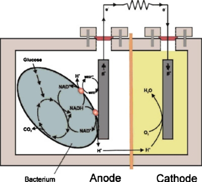
The use of microorganisms as catalysts allows thorough oxidation of biofuels since the microbes contain all the enzymes necessary to complete multistep reaction processes. Even more importantly, microbes have a superior characteristic over enzymes, which is a long period of lifetime. Microbial systems are “live” and can therefore live as long as proper metabolic conditions are provided, while enzymes typically degrade over time.2 In addition, microbes can be less susceptible to poisoning and loss of activity under normal operating conditions. The efficiency of microbial fuel cells is, however, constrained by diffusion of oxygen into the anode chamber due to the severe potential drops associated with microbial consumption of oxygen.5 Consequently, although there are a few exceptions, typical microbial fuel cell designs require physical barriers, such as PEM, for separating anodes and cathodes, as shown schematically in Fig. 1. A membraneless, one-compartment design of the microbial fuel cell was introduced by Liu and Logan.6 The PEM was eliminated by utilizing an air-breathing cathode exposed to the surrounding air. Using glucose as fuel, the maximum power density generated was494 μW m−2, which was more than double the power of an otherwise similar cell with PEM. However, rapid potential drops were observed within 20 h, while the potential of the PEM cell slowly decreased over 95 h. This was mainly due to aerobic oxidation by bacteria in the anode chamber.
Figure 1.
Typical two-compartment layout of a microbial biofuel cell (Ref. 40).Reproduced with permission from Logan et al., Environ. Sci. Technol.ESTHAG0013-936X 40, 5181 (2006). Copyright © 2006 by ACS Publications.
Although microbial bioanodes are well-established in literature, microbial biocathodes are relatively uncommon. Bergel et al.7 introduced a microbial biocathode for oxygen reduction using seawater biofilm that grows in substances immersed in seawater. The biofilm-covered stainless steel cathode was able to support a current density up to0.189 mA m−2, and a power density of 0.032 mW m−2 was achieved.
Enzyme-based biofuel cells
Another pathway toward biofuel cell development is using enzymes as catalysts. Enzymes are directly exposed to fuels during operation, in contrast to microbial cells where the cell wall or cell membrane prevents direct contact with fuels and results in slow mass transport characteristics. Due to the improved mass transport rates, enzyme-based biofuel cells typically produce orders of magnitude higher power densities than microbial biofuel cells.8 Some enzymes such as laccase and bilirubin oxidase can be used for the cathodic oxygen reduction reaction. Recently, Gellett et al.9 published a paper on a biocathode with very promising results. Coupled with a PtRu anode in a direct methanol fuel cell, the laccase-based air-breathing biocathode achieved a maximum current density of 50 mA cm−2 and a peak power density of8.5 mW cm−2, which is the highest overall biofuel cell performance reported so far. This level of power density is comparable to nonbiological microfluidic fuel cells that typically produce power densities on the order of0.1–100 mW cm−2.10
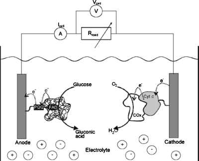
Most enzymes used in biofuel cells have selective active sites that catalyze the fuel much faster than the oxidant; consequently, the cell can be a single-compartment configuration without any physical barrier. Katz and Willner3 designed a single-compartment biofuel cell using glucose and oxygen as fuel and oxidant, respectively, as shown schematically in Fig. 2. One critical drawback associated with this enzyme-based approach is that enzymes commonly have limited lifetimes on the order of 10 days, which needs to be increased considerably for practical applications.2
Figure 2.
A single-compartment enzyme-based biofuel cell running on glucose and O2. Reproduced with permission from Katz and Willner, Environ. Sci. Technol.ESTHAG0013-936X 125, 6803 (2003). Copyright © 2003 by ACS Publications.
MICROFLUIDIC BIOFUEL CELLS
Miniaturization of fuel cells by microfabrication technology
Fuel cells can be an attractive candidate for microelectromechanical system application because they are relatively simple in structure without requiring any moving parts, which potentially results in high yields during mass production. In addition, recent increasing demands on small-scale power sources for portable electronics and implantable devices have significantly boosted the interest in miniaturized fuel cells. More importantly, it has been reported that miniaturized fuel cells enable higher overall energy densities than conventional batteries.10
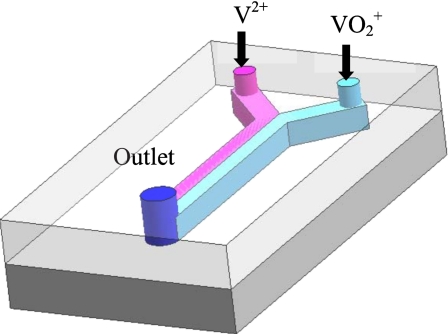
Fuel cell technologies often adopt microfluidic techniques for miniaturization of the devices.10 The typical scale of microfluidic channels is submillimeter in height. As the surface to volume ratio is inversely proportional to the length scale, this ratio can become very high in microfluidic channels and results in more surface area at a given volume, which is beneficial for surface-based fuel cell reactions. Additionally, at small scales, the Reynolds numbers are relatively low and, therefore, the flow is completely laminar, i.e., the viscous effects are dominating over the momentum effects. Consequently, the mixing between multiple fluids occurs mainly by diffusion, while convectional mixing is minimized. In microfluidic fuel cells,10 this retarded mixing can eliminate a physical barrier or a membrane that would be required to separate fuel and oxidant in conventional fuel cells. Ferrigno et al.11 invented a membraneless microfluidic fuel cell using vanadium redox electrolyte, shown schematically in Fig. 3. During operation of the cell, the anolyte (V2+, pink) and the catholyte (VO2+, light blue) were independently introduced into an approximately 200 μm high microfluidic channel featuring colaminar, stratified side by side flow characteristics toward the outlet without a physical barrier between the two streams.
Figure 3.
Schematic of a membraneless fuel cell with a microfluidic channel.
There are two microfabrication methods widely used to build microfluidic fuel cells. Silicon-based micromachining utilizes the conventional chip-manufacturing techniques previously established in semiconductor industries. A silicon substrate is patterned by the lithography step and then wet- or dry-etched in order to form desired cavity-like structures. Finally, either glass or additional silicon wafers are bonded onto the substrate for air tight sealing. The most substantial benefit of the micromachining is the potential for great cost reduction when manufacturing in high volume due to the characteristics of the batch processes.12 The second microfabrication approach is called “soft lithography,”13 which is relatively inexpensive and therefore suitable for rapid prototyping. The desired channel structure is commonly molded in polydimethyl siloxane (PDMS) and subsequently sealed to a solid substrate such as glass, silicon, silicon oxide, silicon nitride, etc.
Very few microfluidic biofuel cells have been reported to date. From the microfabrication point of view, there are two principal explanations for this. First, biocatalytic materials are rarely used in the semiconductor industries and are typically not compatible with clean-room environments. Second, the immobilization of microbes or enzymes has not been well-established in the microfluidic application until recently.8, 14, 15, 16, 17 The first microfluidic biofuel cell with an immobilized enzyme in a microchannel was introduced by Moore et al.8 in 2004, which is 2 years after the first reported microfluidic fuel cell.10
Microfluidic microbial biofuel cells
Microsized microbial fuel cells have several advantages compared to conventional cell architectures including enhanced mass transfer rates, increased surface to volume ratio, and fast response time.18 As mentioned in Sec. 2A, without a physical barrier between two compartments, the microbes or microorganisms at the anode side easily react with the oxidant diffusing from the cathode side and, consequently, reduce the fuel cell performance. The need for a PEM poses a significant constraint for the development of microfluidic microbial fuel cells. The PEM can be placed either in parallel with substrates or orthogonal to substrates. However, due to the nature of microfabrication that mainly depends on the use of planar substrates and two-dimensional lithographic techniques, the parallel configuration that vertically divides two compartments seems more realistic since the PEM can be readily stacked onto the substrates in a sandwich structure between the anode and the cathode layers.
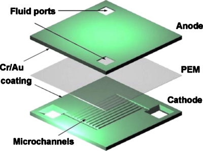
A bulk silicon micromachined microbial biofuel cell was recently introduced by Chiao et al.19 and the exploded view of the cell is shown in Fig. 4. In order to make 80 μm deep microchannels, the silicon wafers for both anode and cathode layers were wet-etched using KOH solution. The obtained channels were 100 μm wide and 6200 μm long. The PEM was then glued to the silicon wafers at the edges using silicone glue. Cultured yeast, S. cerevisiae, was mixed with glucose and fed into the anode chamber, while the catholyte was 0.02M potassium ferricyanide in a 0.1M phosphate buffer. Although the cell performance was relatively low with a peak power density of2.3 nW cm−2, this was an important technical contribution as a feasible miniaturization strategy for microbial fuel cells.
Figure 4.
A bulk micromachined microbial biofuel cell assembled in a sandwich structure. Reproduced with permission from Chiao et al., Environ. Sci. Technol.ESTHAG0013-936X 16, 2547 (2006). Copyright © 2006 by IOP.
Siu and Chiao20 developed a soft lithography-based PDMS biofuel cell using the same yeast, S. cerevisiae, which converts chemical energy stored in blood glucose in the blood stream into electric power. Human plasma containing blood glucose was used as a combined electrolyte and fuel producing a maximum cell voltage of 0.488 V, current density of30.2 μA cm−2, and power density of401.2 nW cm−2. Methylene blue (MB) was used as an electron mediator, which can penetrate the cell wall to the microbial interior. More than 70 000 micropillars (8 μm high and 40 μm×40 μm wide) favorably increased the active electrode area on the PDMS by a factor of 1.8. With the aid of microfluidics, the use of human blood component both as the electrolyte and as the fuel supply tremendously opens the possibility of a long-term miniature power source for implantable devices.
Qian et al.21 reported a microfluidic biofuel cell based on marine bacteria, S. oneidensis strain MR-I, with lactate as fuel. The cell consisted of a vertically stacked 1.5 μl anode chamber and 4 μl cathode chamber made of SU-8 and PDMS, respectively, and separated by a Nafion membrane. A maximum current density of 13 μA cm−2 and a power density of 150 nW cm−2 were achieved.
A microfabricated microbial fuel cell that uses exoelectrogenic bacteria, G. sulfurreducens, and acetate as fuel was reported by Parra and Lin.22 The cell structure followed a typical two-compartment design with a PEM in the middle and the anode consisted of an array of patterned gold electrodes. The system polarization and the power density increased over time as the bacteria gradually colonized the electrode surface. With 1 mm2 anode area, the fuel cell reached a peak power density of 0.012 mW cm−2 and a maximum current density of0.14 mA cm−2.
Microfluidic enzymatic biofuel cells
Complementary to the cell performance advantage, the enzyme-based biofuel cells allow particular merits over the microbial biofuel cells if combined with the microfluidics. Unlike microbes or microorganisms, enzymes can react preferably to a fuel in the anode or an oxidant in the cathode if carefully treated and the fuel crossover becomes less problematic.23 This eliminates the needs for the PEM and therefore leads to simplified structures, making microfabrication more applicable. Immobilization techniques of some enzymes on conductive supports in the microfluidic applications are available in literature8, 24, 25 and was pioneered by Moore et al.8 Alcohol dehydrogenase (ADH) was successfully immobilized onto a carbon microelectrode placed in a 100 μm deep microchannel. Supported by NAD+ and methylene green immobilized electron mediator layers, the microfluidic bioanode produced a maximum current density of 53 μA cm−2 when paired with an external platinum cathode. The modest performance was limited by the diffusion rate of NADH within the enzyme immobilization layers.
A membraneless microfluidic biofuel cell using 2,2′-azinobis (3-ethylbenzohiazoline-6-sulfonate) (ABTS) as a redox mediator was introduced by Lim and Palmore.26 Colaminar flows of anolyte and catholyte were supplied through a microchannel. ABTS was used to reduce oxygen to water using the fungal enzyme, laccase, as a catalyst for electron transfer. Parametric studies were performed to identify the impact of electrode length and spacing on the cell performance. It was found that splitting a single electrode into two or more smaller electrodes and separating them by a distance equal to three times their length increased the maximum power density by 25%, compared to a single electrode configuration with identical electroactive area.
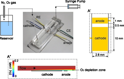
Togo et al.24 developed an enzyme-based bioanode using vitamin K3 as a mediator during catalytic oxidation of NADH by diaphorase (Dp). Glucose was oxidized by a Dp∕glucose dehydrogenase (GDH) enzyme bilayer and the inner Dp layer was coimmobilized with VK3-modified poly-L-lysine(PLL-VK3). The schematic of the bioanode is shown in Fig. 5. In a more recent report from Togo et al.,25 an immobilized bilirubin oxidase-adsorbed O2 biocathode was developed to supplement the bioanode and integrated into a microfluidic biofuel cell format, as illustrated in Fig. 6. The cathode was strategically placed upstream of the anode and, therefore, when the mixture of fuel and oxidant (air saturated glucose solution) was supplied, the consumption of O2 at the upstream cathode protected the downstream anode from interfering O2 molecules and consequently improved cell performance.
Figure 5.
A glucose fuelled bioanode catalyzed by PLL-VK3∕Dp∕GDH. Reproduced with permission from Togo et al., Environ. Sci. Technol.ESTHAG0013-936X 52, 4669 (2007). Copyright © 2007 by Elsevier.
Figure 6.
Schematic illustration of a microfluidic biofuel cell consisting of an upstream biocathode and a downstream bioanode integrated in a PDMS structure with immobilized enzymes as catalysts. A cross-sectional view of the O2 distribution along the channel is shown at the bottom. Reproduced with permission from Togo et al., Environ. Sci. Technol.ESTHAG0013-936X 178, 53 (2008). Copyright © 2008 by Elsevier.
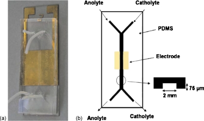
An enzymatic biofuel cell using colaminar flow of glucose and O2 in a Y-shaped microfluidic channel was developed by Zedba et al.,27 as illustrated in Fig. 7. At the anode, the glucose was oxidized by glucose oxidase (GOD) with Fe(CN)63−, whereas at the cathode, the oxygen was reduced by the laccase in the presence of ABTS as a reduction mediator. The anolyte consisted of GOD (0.5 mg ml−1) and Fe(CN)63− (10 mM) in neutral phosphate buffer, while the catholyte solution had laccase (0.5 mg ml−1) and ABTS (5 mM) in 0.2M citrate buffer atpH 3. The assembled biofuel cell produced a maximum power density of 110 μW cm−2 at 0.3 V with 10 mM glucose at 23 °C and a maximum current density of690 μA cm−2, and demonstrated the feasibility of independently tuned colaminar microfluidic streams to optimize enzyme activity.
Figure 7.
An enzymatic glucose/ O2 microfluidic biofuel cell.Reproduced with permission from Zebda et al., Environ. Sci. Technol.ESTHAG0013-936X 11, 592 (2009). Copyright © 2009 by Elsevier.
CHALLENGES AND OPPORTUNITIES IN MICROFLUIDIC BIOFUEL CELLS
Immobilization and lifetime
Immobilization techniques that allow the biocatalysts to be fixed to the electrode surface provide many benefits when dealing with biological materials. The immobilized biomaterials typically have increased compliance to changes in temperature orpH, which can improve stabilities as well as lifetimes.4 Additionally, the close proximity to the electrodes of the immobilized biocatalysts potentially reduces Ohmic losses because the electrodes can collect electrons directly from the reaction sites with less electrical resistance.
The benefits from immobilizing biocatalysts can also be applied to the microfluidic fuel cells. Immobilization strategies of several different enzymes, such as alcohol dehydrogenase,8 glucose dehydrogenase,24 diaphorase,24 and bilirubin oxidase,25 have been reported for microfluidic fuel cell applications. In general, a solution containing enzyme, sometimes with a mediator, is mixed with a polymer agent and coated on the electrode surface. After the solvent is evaporated, the enzyme and the mediator are held in place by the polymerized films. This approach, however, potentially reduces the activity of the enzyme because the active site of the immobilized enzyme may be blocked by the polymer films.8 The immobilization of enzymes can be improved by employing the cross-linking method in which the enzyme is covalently bonded to a substrate through a chemical reaction. The active sites of the enzymes are then fully exposed to the fuel so that their activities are maximized, consequently improving cell performance.28 He et al.29 introduced another immobilization method for monolith microreactors in which a GOD enzyme is immobilized by electrostatic attraction between electronegative enzymes and electropositive polyethylenimine polymer. More than 98% of the immobilized enzyme remained in an active conformation, thus improving enzyme kinetics.
An intrinsic drawback of enzymatic biofuel cells is the relatively short lifetime of enzymes, which is on the order of 10 days.30 An effective way to increase the stability, longevity, and reusability of the enzymes using magnetic iron nanoparticles was recently reported.31 The magnetic iron nanoparticles effectively shielded trypsin and peroxidase enzymes from getting oxidized and self-digested, thereby dramatically increasing the enzyme lifetimes from a few hours to several weeks.
In the microfluidic microbial fuel cells reported so far, the biocatalytic microbes were typically suspended in electrolytes and immobilizing microorganisms in microscale channels have not yet been fully explored. A significant research thrust in this area is expected and would likely have a major impact on the development of next generation microbial fuel cells. A major advantage of microbes over enzymes is longevity and stability over time. Microorganisms can live as long as proper metabolic conditions are maintained, while enzymes tend to degrade over time.2 In this context, microfluidic fuel cell designs can provide improved control over local conditions by exposing the organisms to a continuous microfluidic flow of fresh, nutritional solution while rapidly removing products and waste.
Mediated electron transfer
In order to improve the overall efficiency, biofuel cells frequently adopt a mediator (cofactor) molecule as an electron relay.2 The identification of more robust and efficient mediators, microbes, and enzymes has been an active research area for decades. For example, Davis and Yarborough32 showed that much larger currents could be obtained upon the addition of methylene blue as a mediator to a system of glucose oxidase-based cell. In the microfluidic biofuel cell application, a methylene-blue-mediated microbial fuel cell was introduced by Siu and Chiao,20 and Togo et al.24 used vitamin K3 as a mediator for a microfluidic enzyme-based bioanode. Further research is required to identify mediators with electrochemical potentials very close to those of the enzyme active sites,2 improve mediator arrangements, and coimmobilize mediators and biocatalysts more effectively in the microfluidic environment.
Fabrication and design
As previously discussed, oxygen crossover causes severe problems in microbial fuel cells since the microbes at the anode side can easily react with the oxidant if it diffuses across from the cathode side. This makes the PEM an inevitable component in microbial fuel cells and the same applies to the microfluidic microbial fuel cells. Since the silicon-based microfabrication mainly depends on the use of planar substrates and two-dimensional lithographic techniques, a sandwich structure with a stack of substrates and PEM layers is the preferred approach. Stacking multiple layers of substrate and PEM, however, is still at the proof-of-concept level due to the lack of assembly techniques in the wafer-level batch processes. The process flow must be drawn in advance, depending on whether a wafer-level assembly or individual chip-level bonding is more appropriate. A precise aligning and bonding strategy for PEM with substrates must be established accordingly, which can be another significant technical challenge.
On the other hand, microfluidic enzyme-based biofuel cells can be designed without the PEM. The retarded mixing maintained toward the outlet of a microfluidic channel allows the fuel and oxidant to be supplied individually in a colaminar stratified flow without a separator between the streams. As a consequence of the selective properties of some enzymes and enzyme∕mediator combinations, the fuel and oxidant can even be introduced as a single mixed solution provided the preferential reaction routes of these biocatalytic entities. Katz and Willner3 designed a single-compartment biofuel cell and employed a cross-linked, reconstituted glucose oxidase (GOx) that operated at a high electron transfer rate exceeding that of native GOx with oxygen, making the anode insensitive to the presence of oxygen. From the microfabrication point of view, the single-compartment design tremendously simplifies the device layouts and the standard batch processes can potentially be applicable.
In addition to the topics covered in this section, although some preliminary analytical33 and computational models34 are available, more fundamental research is required to support the development and design of more practical microfluidic biofuel cell devices. More thorough understanding of the bioelectrochemical kinetics and mass transport phenomena are anticipated to lead to material, component, and cell-level design improvements as well as re-engineered microfluidic biofuel cell architecture.
Performance
The performance of the biofuel cells reviewed in this paper is summarized in Table 1 in the form of maximum cell voltage, current density, and power density. In general, the microfluidic microbial fuel cells had relatively low power densities of 10−4 mW cm−2 or less. The fuel must be transported through the cell membrane of the microorganism, which significantly slows down the rate of fuel delivery and consequently reduces the power density. In addition, microbes tend to consume electrons for maintaining cell functions, which again lowers the cell performance.
Table 1.
Performance data of the biofuel cells reviewed in this paper. The current and power densities are based on the electrode surface area.
| Category | Ref. | Fuel | Oxidant | Maximum cell voltage (V) | Maximum current density (mA cm−2) | Maximum power density (mW cm−2) | Comments |
|---|---|---|---|---|---|---|---|
| Microbial | Liu and Logana | Glucose | Air | 0.52 | ⋯ | 0.0494 | Single compartment |
| Enzymatic | Gellett et al.b | Methanol | Air | 0.65 | 50 | 8.5 | PtRu anode |
| Enzymatic | Katz and Willnerc | Glucose | O2 | 0.12 | 0.55 | 0.021 | Single compartment |
| Microfluidic∕ microbial | Chiao et al.d | Glucose | [Fe(CN)6]3− | 0.45 | 0.016 | 2.3×10⁻⁶ | PEM |
| Microfluidic∕ microbial | Siu and Chiaoe | Glucose | [Fe(CN)6]3− | 0.488 | 0.03 | 4.01×10⁻⁴ | PEM |
| Microfluidic∕ microbial | Qian et al.f | Lactate | [Fe(CN)6]3− | ⋯ | 0.013 | 1.5×10⁻⁴ | PEM |
| Microfluidic∕ microbial | Parra and Ling | Acetate | O2 | 0.619 | 0.14 | 0.012 | PEM |
| Microfluidic∕ enzymatic | Moore et al.h | Ethanol | Air | 0.34 | 0.053 | 5×10⁻³ | External cathode |
| Microfluidic∕ enzymatic | Lim and Palmorei | Acetate | Air | 0.4 | 0.45 | 25×10−3 | |
| Microfluidic∕ enzymatic | Togo et al.10 | Glucose | O2 | 0.55 | 0.065 | ⋯ | Fuel∕ O2 mixture |
| Microfluidic∕ enzymatic | Zebda et al.11 | Glucose | O2 | 0.55 | 0.69 | 0.11 | Y-shaped channel |
The microfluidic enzymatic biofuel cells produced several orders of magnitude higher power densities than the microbial fuel cells (∼10−3 mW cm−2or higher). Zedba et al.27 achieved a power density of 0.11 mW cm−2 with a Y-shaped microfluidic fuel cell architecture, which is the highest power density reported in microfluidic biofuel cells to date. Further advancements would, however, be required for microfluidic biofuel cells to compete with nonbiological cells that are often capable of producing∼10–100 mW cm−2.10 Improved microfluidic cell designs with advanced immobilization schemes incorporating high-performance enzymes such as the laccase-based biocathode recently demonstrated by Gellett et al.9 combined with high-surface area electrodes and enhanced rates of convective-diffusive reactant transport could conceivably achieve this target.
FUTURE PERSPECTIVES
Microfluidic microbial fuel cells
Despite their relatively low performance, microbial fuel cells can still be an attractive alternative power source for a host of low-power, long-term applications when integrated on-chip in a microfluidic device. Implantable medical devices such as heart pacemaker and glucose sensor can be potential customers of microfluidic microbial fuel cells since they require longevities of years for in vivo operations at a compact size. As previously mentioned in Sec. 3B, S. cerevisiae converts chemical energy stored in glucose in the human blood stream into electrical energy20 and would be readily applicable to implantable power generation with “infinite” reactant supply. Typical requirements for pacemaker batteries, which include 5 yr lifetime, open circuit voltage of 2.8 V, total energy delivered of25 μJ∕pulse,35 can serve as relevant targets for the development of microfluidic microbial fuel cells.
For further improved performance, significant research activities on immobilizing microbes are anticipated in microfluidic applications. The use of mediator molecules would be combined for higher efficiencies and immobilizing both microbes and mediators will be explored in parallel. Some microbe immobilization methods are already available on larger scales; for instance, Meena and Raja36 showed immobilization of S. cerevisiae by gel entrapment using various metal alginates.
Biocompatibility must be addressed for implantable device applications. During in vivo operation, the devices must be capable of existing in the physiological environment without unacceptable biofouling occurring over time, which otherwise would lead to fouling of the devices and potentially to physiological harm to the human body.5 Maluf37 claimed that preliminary medical evidence indicates that silicon is benign in the human body. However, biocompatibility issues on the commonly used materials in microfabrication, including silicon, still cause scientific arguments and require further investigations.38
Microfluidic enzymatic fuel cells
Due to the limited lifetime of enzymes, a microfluidic enzyme-based fuel cell can find its potential applications where the device does not require long-term operations(<10 days). Portable electronic devices can be a good example;2 if mass produced in high volume, microfluidic enzymatic fuel cells would be cost-effective and therefore disposable. However, significant research thrusts are required since the current performance of the microfluidic enzymatic fuel cells is not comparable to the current Li-ion battery technologies that typically operate at an open circuit voltage of 3.7 V with a total energy capacity of 2250 mA h in a compact form.39 The future research opportunities include (a) identifying more robust and active enzymes as well as mediators, if required; (b) more effectively immobilizing enzymes and mediators in microfluidic environments; and (c) preferably increasing stability and longevity of enzymes.
CONCLUSION
As a compact and green energy source, biofuel cells in microfluidic architecture can be an effective solution for small-scale power source applications such as biological sensors, implantable medical devices, and portable electronics. Significant research advancements, however, must be made to witness them in realistic and practical applications. More fundamental understanding of biocatalytic activities in parallel with scientific efforts on the device configurations will help establish future guidelines for developing microfluidic biofuel cells.
ACKNOWLEDGMENTS
Funding for this research provided by the Natural Sciences and Engineering Research Council of Canada and a Simon Fraser University President’s Research Start-up Grant is highly appreciated.
References
- Mench M. M., Fuel Cell Engines (Wiley, New York, 2008). 10.1002/9780470209769 [DOI] [Google Scholar]
- Bullen R. A., Arnot T. C., Lakeman J. B., and Walsh F. C., Biosens. Bioelectron. 21, 2015 (2006). [DOI] [PubMed] [Google Scholar]
- Katz E. and Willner I., J. Am. Chem. Soc. 125, 6803 (2003). 10.1021/ja034008v [DOI] [PubMed] [Google Scholar]
- Grunwald P., Biocatalysis: Biochemical Fundamentals and Applications (Imperial College Press, London, 2009). [Google Scholar]
- Davis F. and Higson S. P. J., Biosens. Bioelectron. 22, 1224 (2007). 10.1016/j.bios.2006.04.029 [DOI] [PubMed] [Google Scholar]
- Liu H. and Logan B. E., Environ. Sci. Technol. 38, 4040 (2004). 10.1021/es0499344 [DOI] [PubMed] [Google Scholar]
- Bergel A., Feron D., and Mollica A., Electrochem. Commun. 7, 900 (2005). 10.1016/j.elecom.2005.06.006 [DOI] [Google Scholar]
- Moore C. M., Minteer S. D., and Martin R. S., Lab Chip 5, 218 (2005). 10.1039/b412719f [DOI] [PubMed] [Google Scholar]
- Gellett W., Schumacher J., Kesmez M., Le D., and Minteer S. D., J. Electrochem. Soc. 157, B557 (2010). 10.1149/1.3309728 [DOI] [Google Scholar]
- Kjeang E., Djilali N., and Sinton D., J. Power Sources 186, 353 (2009). 10.1016/j.jpowsour.2008.10.011 [DOI] [Google Scholar]
- Ferrigno R., Stroock A. D., Clark T. D., Mayer M., and Whitesides G. M., J. Am. Chem. Soc. 124, 12930 (2002). 10.1021/ja020812q [DOI] [PubMed] [Google Scholar]
- Senturia S. D., Microsystem Design (Kluwer, Dordrecht, 2001). [Google Scholar]
- McDonald J. C., Duffy D. C., Anderson J. R., Chiu D. T., Wu H. K., Schueller O. J. A., and Whitesides G. M., Electrophoresis 21, 27 (2000). [DOI] [PubMed] [Google Scholar]
- Honda T., Miyazaki M., Nakamura H., and Maeda H., Chem. Commun. (Cambridge) 2005, 5062. [DOI] [PubMed] [Google Scholar]
- Yamaguchi H., Miyazaki M., Honda T., Briones-Nagata M. P., Arima K., and Maeda H., Electrophoresis 30, 3257 (2009). 10.1002/elps.200900134 [DOI] [PubMed] [Google Scholar]
- Thomsen M. S., Polt P., and Nidetzky B., Chem. Commun. (Cambridge) 2007, 2527. [DOI] [PubMed] [Google Scholar]
- Laiwattanapaisal W., Yakovleva J., Bengtsson M., Laurell T., Wiyakrutta S., Meevootisom V., Chailapakul O., and Emneus J., Biomicrofluidics 3, 014104 (2009). 10.1063/1.3098319 [DOI] [PMC free article] [PubMed] [Google Scholar]
- Wang H. -Y., Bernarda A., Huang C. -Y., Lee D. -J., and Chang J. -S., Bioresour. Technol. 102, 235 (2011). 10.1016/j.biortech.2010.07.007 [DOI] [PubMed] [Google Scholar]
- Chiao M., Lam K. B., and Lin L. W., J. Micromech. Microeng. 16, 2547 (2006). 10.1088/0960-1317/16/12/005 [DOI] [Google Scholar]
- Siu C. P. B. and Chiao M., J. Microelectromech. Syst. 17, 1329 (2008). 10.1109/JMEMS.2008.2006816 [DOI] [Google Scholar]
- Qian F., Baum M., Gu Q., and Morse D. E., Lab Chip 9, 3076 (2009). 10.1039/b910586g [DOI] [PubMed] [Google Scholar]
- Parra E. and Lin L., Proceedings of MEMS, 2009, Vol. 22, p. 31.
- Cheng S., Liu H., and Logan B., J. Am. Chem. Soc. 230, U1758 (2005). [Google Scholar]
- Togo M., Takamura A., Asai T., Kaji H., and Nishizawa M., Electrochim. Acta 52, 4669 (2007). 10.1016/j.electacta.2007.01.067 [DOI] [Google Scholar]
- Togo M., Takamura A., Asai T., Kaji H., and Nishizawa M., J. Power Sources 178, 53 (2008). 10.1016/j.jpowsour.2007.12.052 [DOI] [Google Scholar]
- Lim K. G. and Palmore G. T. R., Biosens. Bioelectron. 22, 941 (2007). 10.1016/j.bios.2006.04.019 [DOI] [PubMed] [Google Scholar]
- Zebda A., Renaud J., Cretin M., Pichot F., Innocent C., Ferrigno R., and Tingry S., Electrochem. Commun. 11, 592 (2009). 10.1016/j.elecom.2008.12.036 [DOI] [Google Scholar]
- Sheldon R. A., Biochem. Soc. Trans. 35, 1583 (2007). 10.1042/BST0351583 [DOI] [PubMed] [Google Scholar]
- He P., Greenway G., and Haswell H. J., Microfluid. Nanofluid. 8, 565 (2010). 10.1007/s10404-009-0476-8 [DOI] [Google Scholar]
- Kim J., Jia H. F., and Wang P., Biotechnol. Adv. 24, 296 (2006). 10.1016/j.biotechadv.2005.11.006 [DOI] [PubMed] [Google Scholar]
- Sharma A., Qiang Y., Antony J., Meyer D., Kornacki P., and Paszczynski A., IEEE Trans. Magn. 43, 2418 (2007). 10.1109/TMAG.2007.893849 [DOI] [Google Scholar]
- Davis Y. B. and Yarborough H. F., Science 137, 615 (1962). 10.1126/science.137.3530.615 [DOI] [PubMed] [Google Scholar]
- Kjeang E., Roesch B., McKechnie J., Harrington D. A., Djilali N., and Sinton D., Microfluid. Nanofluid. 3, 403 (2007). 10.1007/s10404-006-0128-1 [DOI] [Google Scholar]
- Kjeang E., Sinton D., and Harrington D. A., J. Power Sources 158, 1 (2006). 10.1016/j.jpowsour.2005.07.092 [DOI] [Google Scholar]
- Mallela V. S., Ilankumaran V., and Rao N. S., Ind. Pacing & Electrophy. 4, 201 (2004). [PMC free article] [PubMed] [Google Scholar]
- Meena K. and Raja T. K., World J. Microbiol. Biotechnol. 22, 651 (2006). 10.1007/s11274-005-9085-1 [DOI] [Google Scholar]
- Maluf N., An Introduction to Microelectromechanical Systems Engineering (Artech House, Boston, 2000). [Google Scholar]
- Madou M., Fundamentals of Microfabrication (CRC, Boca Raton, 2002). [Google Scholar]
- See Individual Data Sheet for CGR18650CG http://www.panasonic.com/industrial/batteries-oem/oem/lithium-ion.aspx.
- Logan B. E., Hamelers B., Rozendal R. A., Schrorder U., Keller J., Freguia S., Aelterman P., Verstraete W., and Rabaey K., Environ. Sci. Technol. 40, 5181 (2006). 10.1021/es0605016 [DOI] [PubMed] [Google Scholar]


