

Abstract
Dynamin and other proteins of the dynamin superfamily are widely used by cells to sever lipid bilayers. During this process, a short helical dynamin polymer (one to three helical turns) assembles around a membrane tubule and reduces its radius and pitch upon guanosine triphosphate hydrolysis. This deformation is thought to be crucial for dynamin's severing action and results in an observable twisting of the helix. Here, we quantitatively characterize the dynamics of this deformation by studying long dynamin helices (many helical turns). We perform in vitro experiments where we attach small beads to the dynamin helix and track their rotation in real time, thus collecting information about the space and time dependence of the deformation. We develop a theoretical formalism to predict the dynamics of a mechanically continuous helix deforming on long timescales. Longer helices deform more slowly, as predicted by theory. This could account for the previously reported observation that they are less fission-competent. Comparison between experiments and our model indicates that the deformation dynamics is dominated by the draining of the membrane out of the helix, allowing quantification of helix-membrane interactions.
Introduction
Living cells are open systems, which continuously exchange matter with their surroundings. A major route for these exchanges is membrane traffic, during which lipid membranes are shaped, fissioned, and fused. The dynamin protein is a tool used by eukaryotic cells to break membranes apart (1). This happens during clathrin-coated endocytosis, for example. Toward the end of this endocytosis process, a roughly spherical membrane bud is attached to the cell membrane by a thin membrane neck. Dynamin polymerizes into a helix of internal radius r = 10 nm and pitch 2πp = 13 nm around this neck and severs it upon guanosine triphosphate (GTP) hydrolysis (2).
In vitro, long (several tens of micrometers) helical dynamin-covered membrane tubules (henceforth referred to as tubes) form in the absence of GTP when dynamin is added to a negatively charged membrane template (3). Addition of GTP induces a deformation of the tubes, and their radius and pitch become r + Δr = 5 nm and 2π(p + Δp) = 9 nm, respectively, while the dynamin helix as a whole undergoes a right-handed twist (Δr and Δp are negative). At the structural level, this deformation is related to a conformational change of dynamin: in the constricted state, dynamin dimers are more condensed toward the inside of the tube, and each helical turn comprises 13 dimers, compared to 14 in the relaxed state (4). GTP hydrolysis by dynamin is required for tube breaking (3), suggesting a relationship between this conformational change and fission.
The precise biochemical and biomechanical processes underlying tube fission are still a matter of debate. It was demonstrated by Danino et al. (5) that breaking requires that the tubes adhere to a solid substrate (6–8). We moreover observed (6) that longitudinal tension increases in tubes rigidly attached at both ends after treatment with GTP. Rupture then occurs within a few seconds, similar to the situation of tubes adhered to a solid substrate. This suggests that force build-up within the dynamin helix is an important condition for fission. Another indication of stress build-up is that tubes treated with GTP tend to form supercoils, which indicates the presence of torque within the helix. However, it was recently observed that helix depolymerization can occur before breakage in tubes treated with GTP (7,8). These studies hypothesize that the main effect of GTP hydrolysis is not to generate stresses, but to break molecular bonds within the dynamin polymer and with the membrane. This would then release the highly constricted membrane, and could lead to spontaneous membrane fission. In this model, breakage would thus be due to depolymerization rather than to deformation and stresses. This raises questions regarding the ability of the dynamin helix to withstand such stresses—i.e., its mechanical continuity—which is required for a deformation-based fission mechanism but would be compromised by a large-scale disassembly of the dynamin polymer.
Another interesting finding, by Pucadyil and Schmid (7), is that tube rupture is less likely in long tubes than in short ones. This observation yields interesting insights into the dynamics of dynamin deformation, the typical timescale of which, it has been suggested (9), is imposed by the damping of tube constriction, torsion, and contraction by friction against the surrounding medium and the membrane. As such effects are more pronounced in longer tubes, they could lead to a slower tube deformation there and therefore hinder fission, as hypothesized previously (10).
In this article, we tackle these issues through a quantitative study of the dynamics of the GTP-induced deformation of dynamin. A good understanding of this phenomenon on the timescales over which fission occurs is an important step toward the characterization of the dynamin severing action and the role of deformation therein. Using a joint experimental and theoretical approach, we clarify the physics of this process.
We first present experiments in which the space-dependent twisting of long tubes is monitored by tracking small polystyrene beads attached to the dynamin coat. This methodology allows us to record the tube rotation velocity and number of turns in several locations as a function of time. A theoretical analysis of the deformation is then proposed, which yields detailed predictions regarding this bead motion. We then combine the results of the two approaches, and show that upon GTP hydrolysis, long dynamin coats are able to withhold stresses as a consequence of their continuity or through viscous coupling over small gaps separating essentially continuous adjacent helices. On observable timescales, which coincide with the timescales implicated in dynamin-mediated fission (6), the rate-limiting step for the dynamics of this deformation is the drainage of the membrane out of the helix. We also gain some geometrical insight into the successive steps involved in the deformation. Finally, we discuss the implications of our findings for dynamin's membrane-severing action, and their potential impact on previously proposed models of dynamin-mediated membrane fission.
Materials and Methods
Lipids
All lipids were purchased from Avanti Polar Lipids (Alabaster, AL). We use a synthetic lipid mixture composed of 30% brain phosphatidylethanolamine (PE), 5% liver phosphoinositides (PIs), 30% palmitoyl-oleoyl phosphatidylserine (POPS), and 35% palmitoyl-oleoyl phosphatidylcholine (POPC) and supplement it with 15% (m/m) cholesterol and 5% (m/m) final phosphatidylinositol-4,5-bisphosphate (PtdIns(4,5)P2). This composition mimics a commercial porcine brain polar lipid extract (141101, Avanti) without the 30% unknown lipids. Nucleotides are obtained from Roche Biosciences (Palo Alto, CA).
Dynamin purification and labeling
Dynamin is purified from six rat brains using the GST-tagged SH3 domain of rat amphiphysin 2 as an affinity ligand (6). After elution with low pH and salt, the two fractions most enriched in dynamin are pooled (2 ml total), dialyzed against storage buffer (20 mM HEPES, pH 7.4, 100 mM NaCl, 50% v/v glycerol—final volume ∼0.5 ml, typical concentration ∼2 mg/ml), flash-frozen in liquid nitrogen, and stored at −80°C. For conjugation to biotin, DSB-X biotin C2-iodoacetamide (D-30753, Invitrogen, Carlsbad, CA) is dissolved into dimethyl sulfoxide (DMSO) at a 10 mg/ml stock. Dynamin is labeled for a few minutes by adding a 10× molar excess of DSB-X. Labeled dynamin is dialyzed against storage buffer, aliquoted, flash-frozen, and stored at −80°C. Thiol-reactive biotin DSB-X ensures good functionality of dynamin after labeling.
Formation of membrane sheets
Glass coverslips 22 × 40 mm in size are cleaned by sonication (5 min) in 1% Decon 90 (Modec, Houston , TX) in distilled water, followed by thorough washing and sonication (5 min) in distilled water to remove any trace of detergent and a final wash with 100% ethanol before storage in ethanol. Coverslips are dried under a N2 flux, and 1-μl droplets of lipid solution (10 mg/ml in pure chloroform) are deposited and allowed to dry on the coverslip. Typically, two drops are deposited at different sites on the same coverslip. The use of pure chloroform is essential to allow lipid droplet drying in a way that is optimal for the subsequent formation of membrane sheets upon hydration. Coverslips are then dried again under vacuum (0.2 millitorr) for at least 1 h and kept up to several days under vacuum.
Tube preparation
Before use, coverslips are placed for 20–30 min in a wet incubator (37°C, 100% humidity) to allow partial hydration of the lipids. Next, a small chamber (∼15-μl volume) is built by placing the coverslip onto a glass slide with lipids facing the glass slide, using a double-sided Scotch (3M, St. Paul, MN) tape as a spacer. The lipids are fully rehydrated by applying to the side of the chamber 15–20 μl of GTPase buffer (20 mM HEPES, pH 7.4, 100 mM NaCl, 1 mM MgCl2), which is taken up into the chamber by capillarity. Lipid deposits then transform into membrane sheets. The glass slide is placed on the stage of an Axiovert 150 microscope (Zeiss, Oberkochen, Germany) for observation with a JAI Pulnix (San Jose, CA) TMR-1405L camera and Streampix software for video acquisition (Norpix, Montreal, Quebec, Canada). A dynamin-containing solution (5 μl) is applied to one side of the chamber and the deformation of membrane sheets produced by its diffusion into the chamber is recorded at normal video rate (30 fps) with high resolution (1300 × 1024) imaging under differential interference contrast (DIC) settings. Nucleotide-containing GTPase buffer (5 μl) is added after formation of the tubes.
Bead labeling and observation
In experiments involving streptavidin-coated polystyrene beads (190-nm diameter, Bangs Labs, Fishers, IN), biotinylated dynamin is used, and the dynamin solution also contains beads at an ∼500- to 1000-fold dilution relative to the commercial stock solution. For the experiments, only tubes adherent to the glass surface at their ends but not throughout their length are selected for observation.
Movie processing and compression
Uncompressed DIC movies (AVI files) are resized, contrasted, and accelerated using the VirtualDub freeware (www.virtualdub.org). Raw movies are compressed using the DivX codec (San Diego, CA) to ensure good quality compression for data storage. For the analysis of bead movement, movies are contrasted using VirtualDub, and transformed to 8-bit grayscale stack (.stk) files using the ImageJ (National Institutes of Health, Bethesda, MD) freeware. The spinning beads are tracked using the optional Tracking function of the Metamorph software (Molecular Devices, Silicon Valley, CA), which detects the beads on each frame by pixel thresholding and returns the center of mass of the selected pixels. The bead trajectories are then analyzed with the pick peaks tool in the Origin Pro software (OriginLab, Northampton, MA), yielding the number of turns as a function of time for each bead. We finally obtain the rotation velocity as a function of both time and position along the dynamin helix.
Real-Time Observation of the Deformation
We follow the rotation of beads attached to dynamin-coated membrane tubules during GTP hydrolysis in vitro. Our setup is similar to one used in a previous study (6), with minor modifications. We first prepare membrane sheets by drying a mixture of pure lipids with 5% phosphatidylinositol-4,5-bisphosphate on a coverslip (this mixture comprises the main components of a plasma membrane in similar proportions—see Materials and Methods). Brain purified dynamin, including 1/5 biotinylated dynamin, and streptavidin-coated polystyrene beads (diameter 190 nm), are then injected into the lipids after rehydration with buffer. As a result, the membrane is deformed into tubules, each coated by a dynamin helix to which beads are anchored through streptavidin-biotin bonds. Tubes are typically several tens of micrometers long, with many beads attached (Fig. 1, a and b). This is in contrast to the procedure in our previous study (6), where only single beads were monitored. To best observe the dynamics along the whole helix, we focus only on tubes that lie more or less parallel to and mostly away from the glass surface forming the bottom of our experimental chamber, which enables free rotation of the beads (Fig. S1). The membrane tubules forming the core of those tubes usually adhere non-specifically to the glass at one of their ends and are connected at the other end to the thick (50 μm) lipid deposit, which acts as a membrane reservoir. Whether the dynamin helix itself is firmly anchored to the glass or is free to rotate cannot be determined before GTP addition. We next inject 100 μM GTP into the chamber and monitor the rotation of the beads around the tubes (Movie S1). This relatively low GTP concentration leads to a relatively slow bead dynamics (6), which allows for reliable tracking of the beads. Movies are acquired in DIC microscopy at 30 frames/s. We track the displacement of a bead perpendicular to the tube (Fig. 1 c). The beads appear to move right and left of the tube, and each quasiperiod of this motion corresponds to a full rotation of the bead around the tube. We can thus calculate the bead rotation velocity as a function of both time and position along the dynamin helix (Fig. 1 d). Treatment with 100 μM GTP induces no bead detachment but causes the tubes to shrink longitudinally, which occasionally leads to their breakage (6). During this contraction, beads move closer to each other in a homogeneous and well-coordinated manner, suggesting that the coat does not break apart and behaves as a single continuous unit.
Figure 1.
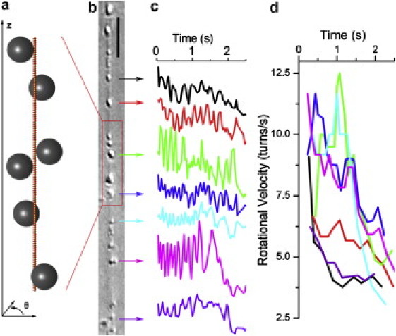
Direct observation of the bead motion. (a) Cartoon of a dynamin-coated membrane tubule with beads attached. (b) DIC image of a tube with several beads. Scale bar, 5 μm. (c) Tracking of seven beads perpendicular to the tube axis. The different amplitudes of oscillation are due to variation in bead size. (d) Rotation velocities as a function of time, calculated from the traces of c and with the same color-coding. The rotation velocity of each bead decreases with time, and neighboring beads have similar rotation velocities. The beads toward the center of the tube rotate the fastest.
More detailed information about the coat continuity is obtained by analyzing the bead rotation. The rotation velocity of each bead usually increases very rapidly after GTP addition, reaches a short plateau phase after three to five turns, then decreases (6) (Fig. 1 d). Some tubes undergo fission at this stage, but for most tubes, the motion smoothly slows down to a halt within a few seconds. It is important to note that the beads all start rotating at the same time and that neighboring beads have a similar rotation velocity (Fig. 1 d and Movie S1). The bead velocity profile indicates the boundary conditions on the dynamin polymer: an increase of the velocity near one end indicates that the helix is free to rotate, whereas a decrease to zero implies that it is blocked (see Fig. S2). The coordinated bead rotation, just like the coordinated longitudinal motion, again suggests that the dynamin coat remains mechanically continuous throughout GTP hydrolysis. This is confirmed by the fact that no obvious discontinuities in the dynamin coat are observed upon GTP treatment in fluorescence microscopy (Fig. S3). Note that discontinuities smaller than the optical resolution might still be present. However, if they are few and <100 nm, they allow the transmission of stresses through viscous coupling and therefore have little influence on the tube dynamics (see Supporting Material).
Theoretical Analysis
Here, we describe the long-time dynamics of a long tube (L ≫ r) during GTP hydrolysis. We show that beads bound to a mechanically continuous deforming helix display distinctive patterns of motion, among which the coordination of neighboring beads discussed above. Even when tube fission occurs, we only consider deformations that precede it (and possibly lead up to it) and thus describe the tube as continuous. We find that on observable timescales it has a diffusive dynamics dominated by an effective helix-membrane friction. These predictions are tested against experimental data in the next section.
We do not describe the local relaxation of the tube but focus on the propagation of the deformation along the tube axis. We are interested in the timescales on which these modes of deformation propagate over distances of order L. It is fairly intuitive that propagation over a longer tube should take a longer time. Therefore, we expect the relaxation timescales of interest to diverge in the so-called hydrodynamic limit L/r→+∞. The systematic study of relaxation phenomena obeying this criterion is known as generalized hydrodynamics, and it can be shown that the complete hydrodynamic behavior of a system can be captured by focusing on its conserved quantities (e.g., mass, momentum, etc.) and broken symmetry variables (describing periodic order in the system) (11). We collectively refer to these as the hydrodynamic variables of the system. Even systems as complex as the dynamin-membrane tube have only a few hydrodynamic relaxation processes, and we are able to give a simple, yet complete mathematical description of its dynamics on those so-called hydrodynamic timescales. This simplicity stems from the fact that generalized hydrodynamics allows us to systematically enclose the unknown microscopic details of the tube in a few phenomenological coefficients. For clarity in this section, we further restrict our discussion to experimentally observable timescales, but a more comprehensive presentation of our formalism is given in Lenz et al. (9).
We follow the standard hydrodynamic approach, which starts by writing conservation equations for the hydrodynamic variables. These equations express, e.g., the time derivative of the mass as a function of a mass current, and we supplement them with a discussion of the timescales involved. For a system close to equilibrium, this current (or flux) is generically proportional to some thermodynamic forces (including, e.g., chemical potential gradients), which characterize how far from equilibrium the system is. These forces are then related to the hydrodynamic variables, which results in a closed set of equations describing the system studied.
Mass conservation and helical structure
We now present the rather minimal set of assumptions required by our formalism: the conservation of dynamin and membrane mass, and a seamless helical structure of the tube. Our approach implies coarse-graining the tube over a lengthscale of ≈r. We thus treat it as a one-dimensional system with spatial coordinate z (Fig. 1 a).
We assume that exchanges of dynamin or membrane between the tube and the surrounding solution are negligible over seconds, and thus the helix and membrane densities, ρh(z,t) and ρm(z,t) (i.e., masses of helix and membrane per unit length), are conserved quantities. Equivalently, we can consider the local tube mass density, ρ(z,t) = ρh + ρm, and mass fraction of dynamin, Φ(z,t) = ρh/ρ, as conserved quantities, which implies the conservation law
| (1) |
where a nonlinear advection term was dropped, as we assume that the tube is weakly displaced from its reference state (defined as its state in the absence of GTP and of externally applied force and torque). Here, J(z,t) is the mass flow of helix in the local center-of-mass reference frame.
We furthermore hypothesize that the helix does not break, and thus retains a solid-like periodic structure throughout. We define as the angle at which the helix intersects the horizontal plane located at altitude z (Fig. 1 a). As the helix rotates or translates, the intersection point between the static plane and the moving helix is displaced, and thus, varies. We further define the torsional strain . Because of the helix continuity, this strain component is a broken-symmetry variable, i.e., plays a similar role to a conserved quantity. Indeed, just like a depletion of tube mass (a conserved quantity) can only occur through mass flow to neighboring regions, a local extension (decrease in strain) of the solid-like helix requires that the neighboring regions be compressed (increase in strain).
On hydrodynamic timescales, all dynamical processes that occur within the tube are slaved to the hydrodynamic variables , , and (here, δ denotes the deviation from the reference state). Thus, we may describe the tube state only by these three degrees of freedom.
Comparison of typical timescales
The fact that the tube has three hydrodynamic variables implies that it has three relaxation modes (11). Because its dynamics is overdamped, all three modes are diffusive. The relaxation of these modes toward the new steady state imposed by GTP hydrolysis is driven by the tube elasticity, which is characterized by its persistence length, (12). Energy dissipation during this process occurs through two different phenomena: hydrodynamic drag against the surrounding water (characterized by the water viscosity, Pa·s) and relative helix-membrane motion, which involves intra-membrane dissipative phenomena (characterized by an inter-monolayer friction coefficient (13)). The two phenomena happen on widely different timescales, as seen when comparing the associated characteristic diffusion coefficients:
| (2) |
Since we are concerned with describing experimental systems with lengths of order 10 μm over timescales of order 1 s, we are only interested in phenomena characterized by diffusion coefficients of order 102 μm2·s–1, i.e., only in those involving helix-membrane friction. The hydrodynamic drag of water is thus neglected in the following analysis, so that no external forces are applied to the tube except at its ends. Using and to denote the local internal longitudinal tension of the tube and its local internal torque, respectively, this implies that σ and τ are independent of z. They are thus equal to the force and torque imposed at the ends of the tube, which we assume to be constant.
Internal forces governing tube relaxation
The relaxation of the tube is driven by the reactive forces conjugate to its hydrodynamic variables: the longitudinal pressure, (which has units of force in a one-dimensional system); the elastic torque, ; and the helix-membrane exchange chemical potential, . All of these vanish in the reference state. They are defined in terms of derivatives of the tube free energy per unit length, , and for small deviations from the reference state they are linearly related to the hydrodynamic variables:
| (3) |
where the 3 × 3 susceptibility matrix χ expresses this linear relation. This matrix characterizes the tube elasticity. The derivatives in Eq. 3 are taken in the tube reference state.
Dissipative processes, including GTP hydrolysis
Whereas the conservative (reactive) part of the tube dynamics close to equilibrium is captured by Eq. 3, dissipative phenomena are described by the flux-force relations in an isothermal tube:
| (4a) |
| (4b) |
| (4c) |
The left-hand sides of Eqs. 4a, 4b, and 4c are equal to the dissipative fluxes of linear momentum (dissipative force), angular momentum (dissipative torque), and helix mass (diffusion flux), respectively. Those fluxes are linearly related to thermodynamic forces (representing the free energy liberated by GTP hydrolysis), , and through the phenomenological transport coefficients , , , and .
Although the values of these coefficients are a priori unknown, only certain couplings are allowed by symmetries. In agreement with structural data (4,14,15), we assume that the tube is nonpolar, i.e., invariant under up-down symmetry. As a consequence, Eqs. 4a and 4b (where the fluxes are even under this transformation), but not Eq. 4c (where the fluxes are odd), involve the chemical potential difference, , between GTP and its hydrolysis products (which is even). Therefore, GTP hydrolysis plays the same role in the tube dynamics as an externally applied force and torque, as seen in Eq. 4. Note that viscous terms are omitted from Eqs. 4a and 4b, as they are subdominant compared to and in the hydrodynamic limit.
The coefficient relates the amount of helix-membrane motion (characterized by J) to the force, , that drives this motion. It is therefore essentially a helix-membrane friction coefficient. Here, we consider that helix-membrane friction stems from intra-membrane dissipative phenomena, and thus involves the membrane viscosity. To be able to quantitatively test this hypothesis, we consider the simplistic model described in our previous article (9), where the helix is rigidly attached to the membrane's outer monolayer, which itself drags against the inner monolayer. This model yields the estimate , which is compared to experimental measurements in the next section. Note that in this formula is related to β and thus characterizes the dominant form of dissipation discussed above (see Eq. 2).
Tube behavior on observable timescales
Combining Eqs. 1, 3, and 4, and using the fact that σ and τ are constants, we find that the hydrodynamic behavior on observable timescales is given by the diffusion equation
| (5) |
The associated relaxation timescale is set by the friction of the helix against the membrane. In a previous article (9), we computed χ using an elastic model of the tube (see also Fig. 3) and predicted .
Figure 3.
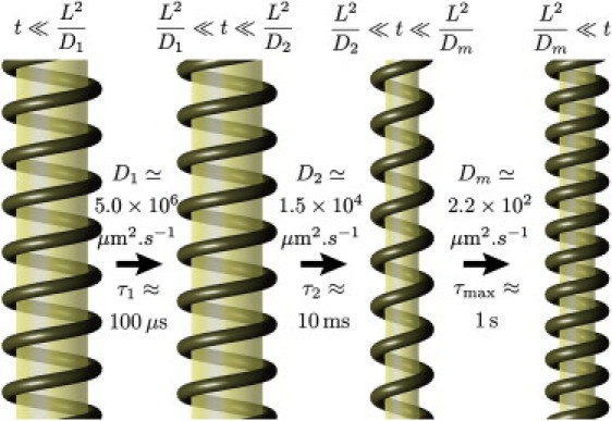
Illustration of the time-dependent deformation as predicted by the full hydrodynamic formalism of Lenz et al. (9). (See the Supporting Material for a proper description of the membrane reservoir.) The images in this figure represent the tube state during the lag phases between the relaxation of the three well-separated diffusive relaxation modes of the tube. See Movie S2 for an animated version. Note that our model allows for both stretching and bending of the membrane, but in practice, the membrane area per polar head varies by <1.5% and the inhomogeneities in membrane radius due to bending are always <7%—they are thus hardly discernible in this figure.
Tube Dynamics Controlled by Membrane Friction
The previous section characterizes the dynamics of long (L ≫ r) unbroken dynamin helices. In this section, we compare its predictions to data from the experiments described in Real-Time Observation of the Deformation. We find that they are indeed compatible, and argue that this can only be accounted for by the fact that helices in our experiments are mostly unbroken. We then discuss the physics underlying the relaxation.
We find that the longest relaxation timescale of the tube apparently diverges with its length, which indicates a hydrodynamic relaxation process. According to our theoretical reasoning, only two types of relaxation processes are compatible with this behavior: 1) friction against water, and 2) friction between the helix and the membrane. According to the estimate of Eq. 2, the timescales involved in 1), are of the order of . The longest relaxation time of the tube is observed to be of the order of 1 s (Fig. 1 d), i.e., much longer than this. This allows us to rule out friction against water as a major influence in the relaxation process on observable timescales. On the other hand, we show below that the relaxation timescale involved in 2), and predicted using our estimate of the friction coefficient is indeed compatible with the experiments. This supports our hypothesis that helix-membrane friction is mostly due to effects related to the membrane viscosity.
Final state of the tube
Let us consider an unbroken helix stuck to the glass at (thus imposing θ(0, t) = 0) and free to rotate at its other end, , and discuss the motion of a bead located at altitude z. As a consequence of the helix continuity, the piece of helix between 0 and z cannot rotate without dragging along the piece between z and L in its rotation. Each turn of helix eventually undergoes an identical twisting deformation and thus rotates the portion of the helix above it by a fixed quantity. As these elementary rotations add up, the total number of rotations of a bead increases linearly with increasing z. This reads , where is a constant. More specifically, this is due to the up-down symmetry of the tube, which imposes that GTP hydrolysis acts as a force and torque and thus imposes a constant strain on the helix.
In Fig. 2 a, we present two experiments where the tubes do not break after addition of 100 μM GTP, which allows us to count the total number of turns of each bead between GTP injection and the end of the deformation. As expected, these data display a linear relationship between bead position z and the total amount of rotation, , with (open circles) and (solid circles). This is to be compared with the structural data of Zhang and colleagues (14,15), where it is stated that the helix goes from 14.2 to 13.2 dimers/helical turn, which corresponds to . Although these numbers are in order-of-magnitude agreement, our measurements yield noticeably smaller values, meaning that tubes submitted to 100 μM GTP (as opposed to the nucleotide concentration of 1 mM used in Zhang and Hinshaw (14)) only reach a partially constricted state.
Figure 2.
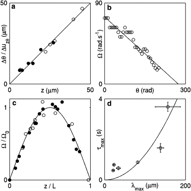
Experimental data validate the predictions from our hydrodynamic formalism, implying that dynamin deforms as a mechanically continuous entity and that this process is damped by an internal friction. (a) Linear relationship between Δθ(z) and z, where Δθ(z) is determined by counting the final number of rotations in a trace similar to those presented in Fig. 1c for the bead located in z. Open and solid circles represent data from two independent experiments. For each of these, the Δθ values are divided by the value of indicated in the main text to collapse the data onto a line. (b) Exponential relaxation of bead rotation on long timescales. As the rotation velocity (measured as in Fig. 1d) decreases, tracking becomes increasingly difficult and no data are collected for rad. (c) Velocity profiles for two independent experiments, each involving a single tube. The Ω values of the experiment represented by open circles and solid circles were divided by and , respectively, and the bead positions, z, were scaled by the independently measured and , respectively, to collapse the data onto a sinusoidal master curve. (d) Dependence of the largest relaxation time (fit procedure described in Fig. S4) on the largest wavelength compatible with the tube boundary conditions. Horizontal error bars represent the estimated uncertainty regarding the length of each tube, and vertical error bars stand for the fit uncertainty as calculated by the Origin software.
These observations are consistent with structural evidence of the up-down symmetry of the helix (14,15). More important, they constitute strong evidence of its mechanical continuity, meaning that if gaps in the helix are present, they are few and significantly smaller than 100 nm. Indeed, larger gaps would spoil the linear relationship observed here (see discussion above and the Supporting Material). Note that large, optically resolvable gaps are observed when multiple dynamin polymers nucleate on a preformed membrane tubule (16), but not when tubes are grown from a flat membrane, as is the case here. The data presented in Fig. 2 a also show that bead rotation in our experiments is not due to the unbraiding of two tubes, as was suggested previously (7) (see Supporting Material).
Bead rotation dynamics
The diffusive dynamics of Eq. 5 predicts the long-time relaxation of bead rotation as a function of space and time. At long times, the strain is dominated by its longest-lived Fourier mode, i.e., the one with the largest wavelength compatible with the boundary conditions. This yields
| (6) |
In this paragraph, we focus our attention on the time dependence of this relaxation, which decays exponentially with time constant
| (7) |
This can be equivalently expressed as
| (8) |
In Fig. 2 b, we test this linear relationship between θ and the rotation velocity, Ω, in an experiment where a 1 mM GTP concentration is used, which allows for the observation of many turns of the bead and therefore provides a stringent test of Eq. 8. The agreement is very good, and the slope of the linear fit yields s. In this experiment, we evaluate the length of the tube to be , which yields . This is in good order-of-magnitude agreement with our theoretical prediction.
Long-time bead velocity profile
Now turning to the spatial profile described in Eq. 6, we expect Ω to have a sinusoidal dependence in the coordinate z. In Fig. 2 c, we plot the value of the velocities of beads attached to two different tubes as a function of their scaled positions and after addition of 100 μM GTP. The motion of neighboring beads is clearly coordinated, as expected from our continuous helix model.
Relation between length and relaxation time
Using sinusoidal fits similar to those seen in Fig. 2 c, we establish that for tubes attached at only one end, whereas for tubes attached at both ends (see Fig. S2; the possibility for a tube attached at both ends to rotate is discussed in the Supporting Material). Therefore, Eq. 7 predicts that long tubes have a slower long-time dynamics than short ones. We test this by measuring for several tubes with either one or two ends attached (fit procedure described in Fig. S4). These data are plotted against in Fig. 2 d.
A quadratic fit corresponding to Eq. 7 is represented by a line in Fig. 2 d and yields , in agreement with our prediction. Note that the experimental relaxation times are larger than predicted by theory for short tubes (). This is likely due to the injection of GTP into the experimental chamber, which takes a few tenths of a second and could interfere with the relaxation of the tube on this timescale: as the amount of available GTP increases with time over this period, the bead rotation tends to accelerate, and the predicted slowing down is not observed until after the end of GTP injection. This leads to an experimental overestimation of that is most apparent in short tubes. Another possible cause for this delay is the inherent timescale associated with GTP hydrolysis by dynamin, which is also of the order of a few hundreds of milliseconds (14). These timescales are negligible in the hydrodynamic limit , where our formalism is valid. Indeed, Fig. 2 d clearly shows that the longest relaxation time of the tubes is an increasing function of their length, which retrospectively justifies our focusing on hydrodynamic timescales. This is further evidence of the mechanical continuity of the tubes used in our experiments, as we would expect a broken long tube to behave similarly to a collection of small tubes (e.g., have the same relaxation time as short tubes), which is not observed here. Finally, the reasonable agreement between the values of Dm inferred from Fig. 2 b (where ) and the value fitted in Fig. 2 d () confirms our prediction that the tube relaxation timescale does not depend on GTP concentration (see Eq. 5).
Full predictions for the deformation dynamics
The good agreement of our theoretical analysis with experimental results suggests that it may also give a reasonable description of dynamin-coated membrane tubes on shorter length- and timescales. In Fig. 3, we present predictions from a detailed analysis of our hydrodynamic formalism (9) (see also Supporting Material) in the case where the tube reaches its full deformation, as when treated with 1 mM GTP (5).
This analysis is based on the changes of pitch and radius of the helix observed by Danino et al. (5), which allow us to infer the active force and torque and describing GTP hydrolysis. We also assume that the helix elastic properties are similar to those of a spring with persistence length (12). This somewhat coarse assumption implies that the details of the deformation described in Fig. 3 are speculative to some extent, although plausible and thermodynamically consistent. A more refined characterization of the matrix χ could be obtained through additional mechanical measurements (e.g., of the compressional elasticity of the helix). We allow membrane bending and stretching and assume that the corresponding moduli have the typical values 10 kBT and (9). This allows us to evaluate the elastic susceptibility matrix χ. As discussed previously, the tube dynamics can be decomposed into three chronologically well-separated diffusive modes, and we evaluate the associated diffusion coefficients, , as well as the amplitude of the deformations, as pictured in Fig. 3.
On short (although hydrodynamic) timescales (), the tube undergoes an almost imperceptible retraction in the vertical direction, without rotation or relative helix-membrane motion—longitudinal friction on the surrounding medium is the dominant dissipative mechanism. On intermediate timescales , the tube radius decreases. Both longitudinal friction and the dissipation associated with the flux of water inside the tube are negligible (9). Rotational friction against water is the dominant dissipative mechanism, and no relative helix-membrane flux occurs (helix and membrane extend longitudinally at the same rate). Only on timescales of order is membrane expelled from the helix to the membrane reservoirs at its boundaries. Fig. 3 shows that this process involves a decrease in tube pitch, which is consistent with the notion that membrane is being squeezed out of the helix.
Discussion
This article describes the deformation dynamics of long dynamin-coated membrane tubules upon GTP hydrolysis as essentially governed by dynamin flow, membrane flow, and the winding of the dynamin helix. Combining experimental data and theoretical analysis, we show that on observable timescales this dynamics essentially consists in the drainage of the membrane out of the mechanically continuous helix by nucleotide-induced effective force and torque. The numerical value of the relevant friction coefficient suggests that dissipation occurs mostly within the lipid bilayer, possibly as strongly dynamin-bound lipids move relative to and exert friction against the surrounding nonbound lipids. As a consequence, short tubes deform more slowly than long ones.
Although our study focuses on long tubes, our results reveal the stability of the dynamin helix throughout GTP hydrolysis, as well as the nature of the out-of-equilibrium interactions between dynamin and membrane. These findings can readily be transposed to short helices such as those encountered in vivo, and are therefore of interest for the study of dynamin in a biological context. Note, however, that the separation of timescales between microscopic and hydrodynamic relaxation processes does not hold in such short helices; for instance, Fig. 2 d shows that dynamin-membrane friction dominates the dynamics only in tubes longer than a few microns. It is therefore likely that other relaxation phenomena also have an influence on the dynamics of short tubes, and it is thus not obvious what mechanisms set the timescale for their breaking.
Our approach also allows us to use macroscopic information from in vitro experiments to predict the shape and dynamics of the helix on small (≈10 nm) lengthscales without need of further structural studies (Fig. 3). This provides a qualitative picture of the microscopic dynamics of the tube.
Our results have implications for the mechanism of dynamin-mediated membrane fission and shed new light on several previous models. A first possibility is that dynamin drives fission purely by constricting the membrane. As indicated in Fig. 3, we expect this type of deformation to take place on timescales of the order of 10 ms after GTP injection. After having been brought into close proximity by constriction, the two sides of the membrane would presumably fuse together to complete fission. This step implicates an energy barrier of several , and may thus take a long time to complete. In our in vitro experiments and in a previous article (6), fission typically occurs a few seconds after GTP injection, and another study (7) reports fission times of several tens of seconds. Since we predict that the radius of the tube shrinks on a much shorter timescale (Fig. 3), we may interpret these fission times as dominated by the barrier crossing step, which could provide insight into the energetics of the membrane fusion process. However, the observation made in other studies (5,6) that anchoring of the tube to the substrate is required for breaking is not accounted for by this mechanism. Pure constriction might thus not be able to account for the dynamin-mediated fission observed in those experiments.
Another proposal is that helix constriction plays a negligible role in membrane fission, whereas an increase in the helix pitch would drive a dramatic thinning of the membrane tubule on short timescales. This would fuse the opposite sides of the tubule (18), leading to breakage. Our predictions of the tube dynamics on timescales ranging from a few hundreds of microseconds (17) to seconds (Fig. 3) suggest that neither this nor dramatic membrane stretching occur on hydrodynamic length- and timescales. If correct, this scenario is therefore likely to apply only to short dynamin helices, such as those observed in vivo.
Our results also allow a discussion of results from more recent studies (7,8), where it is reported that dynamin disassembles from the membrane during GTP hydrolysis. The authors suggest that long dynamin coats are quickly released from the membrane upon GTP addition and are promptly replaced by smaller, more fission-competent coats. This would imply that helix depolymerization is the central event of dynamin-mediated membrane fission, and therefore that dynamin deformation is secondary, if not irrelevant, to its severing action. Our results concerning the mechanical continuity of the dynamin helix upon GTP hydrolysis do not support this picture and indeed suggest that in our experimental system, the mechanochemical action of dynamin is central to its severing action.
Lenz et al. (19) propose that deformation on a timescale shorter than the membrane viscoelastic timescale might lead to a tear in the membrane, possibly through shearing, which could initiate tube fission. We estimate this viscoelastic timescale, τve, as the ratio of a typical lipid surface viscosity, (20), to a typical membrane stretching modulus, (21), yielding . Here, we report that the tube dynamics is slower for longer tubes, which could imply a less efficient tearing action for tubes where , i.e., in tubes longer than , which is a few nanometers. This is compatible with the observation made by Pucadyil and Schmid (7) that long dynamin-covered membrane tubules are less likely to break than short ones. More broadly, this model puts forward the interesting notion that the strong helix-membrane interactions characterized in this article may participate in the destabilization of the bilayer during fission. Such interactions have indeed been shown to be essential for the membrane fission activity of dynamin (22). This finding and our new theoretical insight into dynamin deformation pave the way for further quantitative studies of dynamin-mediated fission.
Acknowledgments
We thank Timo Betz, Pierre Nassoy, and Gilman Toombes for inspiring discussions and critical reading of this manuscript, and Patricia Bassereau for her support and scientific interest in this project.
This work was supported by the Centre National de la Recherche Scientifique (“Interface Physique Chimie Biologie: soutien à la prise de risque”) (A.R.), the Agence Nationale de la Recherche (Young Investigator Program, No. JC08_317536) (A.R.), and the Human Frontier Science Program Career Development Award (No. 0061/2008 to A.R.).
Footnotes
Martin Lenz's present address is James Franck Institute, University of Chicago, 929 E. 57th Street, Chicago, IL 60637.
Supporting Material
References
- 1.Praefcke G.J.K., McMahon H.T. The dynamin superfamily: universal membrane tubulation and fission molecules? Nat. Rev. Mol. Cell Biol. 2004;5:133–147. doi: 10.1038/nrm1313. [DOI] [PubMed] [Google Scholar]
- 2.Takei K., McPherson P.S., De Camilli P. Tubular membrane invaginations coated by dynamin rings are induced by GTP-γ S in nerve terminals. Nature. 1995;374:186–190. doi: 10.1038/374186a0. [DOI] [PubMed] [Google Scholar]
- 3.Sweitzer S.M., Hinshaw J.E. Dynamin undergoes a GTP-dependent conformational change causing vesiculation. Cell. 1998;93:1021–1029. doi: 10.1016/s0092-8674(00)81207-6. [DOI] [PubMed] [Google Scholar]
- 4.Mears J.A., Ray P., Hinshaw J.E. A corkscrew model for dynamin constriction. Structure. 2007;15:1190–1202. doi: 10.1016/j.str.2007.08.012. [DOI] [PMC free article] [PubMed] [Google Scholar]
- 5.Danino D., Moon K.-H., Hinshaw J.E. Rapid constriction of lipid bilayers by the mechanochemical enzyme dynamin. J. Struct. Biol. 2004;147:259–267. doi: 10.1016/j.jsb.2004.04.005. [DOI] [PubMed] [Google Scholar]
- 6.Roux A., Uyhazi K., De Camilli P. GTP-dependent twisting of dynamin implicates constriction and tension in membrane fission. Nature. 2006;441:528–531. doi: 10.1038/nature04718. [DOI] [PubMed] [Google Scholar]
- 7.Pucadyil T.J., Schmid S.L. Real-time visualization of dynamin-catalyzed membrane fission and vesicle release. Cell. 2008;135:1263–1275. doi: 10.1016/j.cell.2008.11.020. [DOI] [PMC free article] [PubMed] [Google Scholar]
- 8.Bashkirov P.V., Akimov S.A., Frolov V.A. GTPase cycle of dynamin is coupled to membrane squeeze and release, leading to spontaneous fission. Cell. 2008;135:1276–1286. doi: 10.1016/j.cell.2008.11.028. [DOI] [PMC free article] [PubMed] [Google Scholar]
- 9.Lenz M., Prost J., Joanny J.-F. Mechanochemical action of the dynamin protein. Phys. Rev. E Stat. Nonlin. Soft Matter Phys. 2008;78:011911. doi: 10.1103/PhysRevE.78.011911. [DOI] [PubMed] [Google Scholar]
- 10.Roux A., Antonny B. The long and short of membrane fission. Cell. 2008;135:1163–1165. doi: 10.1016/j.cell.2008.12.003. [DOI] [PubMed] [Google Scholar]
- 11.Chaikin, P. M., and T. C. Lubensky. 1995. Principles of Condensed Matter Physics. Cambridge University Press, Cambridge.
- 12.Frost A., Perera R., Unger V.M. Structural basis of membrane invagination by F-BAR domains. Cell. 2008;132:807–817. doi: 10.1016/j.cell.2007.12.041. [DOI] [PMC free article] [PubMed] [Google Scholar]
- 13.Evans E., Yeung A. Hidden dynamics in rapid changes of bilayer shape. Chem. Phys. Lipids. 1994;73:39–56. [Google Scholar]
- 14.Zhang P., Hinshaw J.E. Three-dimensional reconstruction of dynamin in the constricted state. Nat. Cell Biol. 2001;3:922–926. doi: 10.1038/ncb1001-922. [DOI] [PubMed] [Google Scholar]
- 15.Chen Y.-J., Zhang P., Hinshaw J.E. The stalk region of dynamin drives the constriction of dynamin tubes. Nat. Struct. Mol. Biol. 2004;11:574–575. doi: 10.1038/nsmb762. [DOI] [PubMed] [Google Scholar]
- 16.Roux A., Koster G., Bassereau P. Membrane curvature controls dynamin polymerization. Proc. Natl. Acad. Sci. USA. 2010;107:4141–4146. doi: 10.1073/pnas.0913734107. [DOI] [PMC free article] [PubMed] [Google Scholar]
- 17.Stowell M.H.B., Marks B., McMahon H.T. Nucleotide-dependent conformational changes in dynamin: evidence for a mechanochemical molecular spring. Nat. Cell Biol. 1999;1:27–32. doi: 10.1038/8997. [DOI] [PubMed] [Google Scholar]
- 18.Kozlov M.M. Dynamin: possible mechanism of “Pinchase” action. Biophys. J. 1999;77:604–616. doi: 10.1016/S0006-3495(99)76917-1. [DOI] [PMC free article] [PubMed] [Google Scholar]
- 19.Lenz M., Morlot S., Roux A. Mechanical requirements for membrane fission: common facts from various examples. FEBS Lett. 2009;583:3839–3846. doi: 10.1016/j.febslet.2009.11.012. [DOI] [PubMed] [Google Scholar]
- 20.Dimova R., Pouligny B., Dietrich C. Pretransitional effects in dimyristoylphosphatidylcholine vesicle membranes: optical dynamometry study. Biophys. J. 2000;79:340–356. doi: 10.1016/S0006-3495(00)76296-5. [DOI] [PMC free article] [PubMed] [Google Scholar]
- 21.Rawicz W., Olbrich K.C., Evans E. Effect of chain length and unsaturation on elasticity of lipid bilayers. Biophys. J. 2000;79:328–339. doi: 10.1016/S0006-3495(00)76295-3. [DOI] [PMC free article] [PubMed] [Google Scholar]
- 22.Ramachandran R., Pucadyil T.J., Schmid S.L. Membrane insertion of the pleckstrin homology domain variable loop 1 is critical for dynamin-catalyzed vesicle scission. Mol. Biol. Cell. 2009;20:4630–4639. doi: 10.1091/mbc.E09-08-0683. [DOI] [PMC free article] [PubMed] [Google Scholar]
Associated Data
This section collects any data citations, data availability statements, or supplementary materials included in this article.