Abstract
Bone is continuously repaired and remodeled through the well-coordinated activity of osteoblasts, which form new bone, and osteoclasts, which resorb it. How osteoclasts sense the properties of the bone surface remains unclear. Combining light and electron microscopy, we compared osteoclast behavior on three distinct surfaces: glass, calcite single crystals, and bone. Podosomes, the basic units of the adhesion structure, and their organization into super-structures, were found to be common to cells attached to all three substrates, while the structure of the resorption organelle, the so-called “ruffled border,” markedly differed. Moreover, the integrity, stability and dynamic behavior of the adhesion super-structures also fundamentally differed, depending on the substrate. We conclude that osteoclasts sense the local properties of the underlying substrate and respond to these signals, both locally and globally.
Keywords: Bone, Calcite, Cell adhesion, Cell recognition, Osteoclast
Introduction
Bone is composed of collagen fibers, mineralized by carbonated apatite crystals that grow in the gap regions of the individual fibrils. During bone maturation, the dimensions of the platelet-like crystals increase to such an extent that they expand beyond the collagen gap regions, leading to an increase in the mineral-to-collagen ratio. The resulting increase in mineralization alters the chemical composition of the fibril surface and the mechanical properties of bone.[1-3] To maintain its functionality, in particular in response to load, bone must be repaired when damaged. Bone thus continuously undergoes remodeling, based on the well-balanced cellular activity of osteoblasts, which deposit new bone, and osteoclasts, responsible for bone resorption. The balance between the activities of these two cell types is essential for normal bone functioning. Indeed, several bone diseases, among them osteoporosis, caused by excessive osteoclast action, and osteopetrosis, caused by reduced osteoclast activity, are related to a pathological imbalance between their activities.[4]
Bone resorption by osteoclasts is performed by a specialized “resorptive apparatus,” consisting of a cytoskeleton-associated sealing zone through which the cells attach to appropriate sites along the bone surface. Acidification of the cavity between the cell membrane and the bone surface, and secretion of proteolytic enzymes into it, occurs via a specialized organelle known as the ruffled border.[5] This activity, in turn, results in local dissolution of the mineral, followed by digestion of the collagen matrix, thereby forming a “resorption pit”.[6, 7]
Critical components in the assembly of this complex system are the podosomes, small, actin-associated adhesion sites,[8-10] which assemble into “clusters,” and eventually develop the sealing zone. [11] The sealing zone delimits the membrane domain where the ruffled border is formed.
In the present study, we examined how osteoclast activity is influenced by the underlying matrix. The bone resorption activity of osteoclasts is regulated at many levels, including differentiation of their monocytic precursors, fusion into multi-nucleated cells, migration to the resorption site, polarization of the mature osteoclasts, and the assembly of a podosome-based sealing zone.[12]
This complex regulation of osteoclast function appears to be strongly dependent on surface chemistry, topography, and mechanical properties of the underlying bone. For example, osteoclast activity in vitro was shown to increase dramatically on old bone, relative to new bone.[13] Osteoclast resorption has also been examined using a variety of natural (e.g., bone) or artificial matrices, the latter including resorbable substrates such as hydroxyapatite powders and ceramics.[14-22] Thus, β-tricalcium phosphate is more degradable than calcite[19] and carbonated apatite more than octacalcium phosphate or amorphous calcium phosphate[22]. Carbonated apatite, hydroxyapatite, and β-tricalcium phosphate are more adhesive than octacalcium phosphate, dicalcium phosphate dehydrate tetracalcium phosphate and α-tricalcium phosphate[21]. However it is not understood why certain substrates favor osteoclast adhesion and subsequent degradation while others do not, and what features of the cells are affected by the surface to which they adhere.
Here, we compared the behavior of cultured osteoclasts on three distinct surfaces: glass, calcite crystals and bone. Calcite large single crystals were chosen as a convenient, resorbable substrate because they are homogeneous, and also well-characterized chemically, structurally and topographically.
The differential effects of these surfaces on podosome formation, assembly into sealing zone-like structures, and dynamic reorganization of the podosomal system enabled us to define specific parameters of osteoclast behavior that are regulated by the underlying substrate, as opposed to substrate-independent parameters. In so doing, we demonstrated that while the properties of the substrate do not affect the basic architecture of the podosomal units, they strongly influence the dynamic formation of ring-like podosomal super-structures, and the stability of these rings.
Results
Calcite as a substrate for osteoclast culture
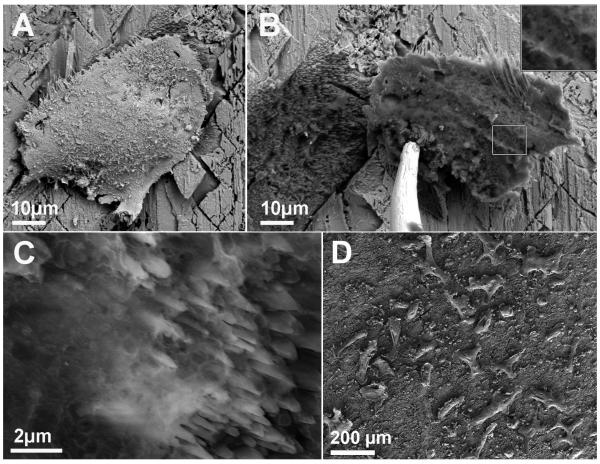
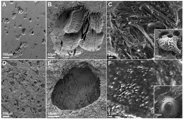
Large fragments of calcite (5-8mm) were cut from centimeter-sized geological single crystals (feldspar) and pre-incubated with the adhesion protein vitronectin to facilitate osteoclast adhesion to the crystal surfaces. Differentiated osteoclasts were cultured for four days on the crystals. Osteoclasts actively resorb calcite both in the presence and in the absence of vitronectin. Pre-incubation of calcite with vitronectin, however, resulted in a tenfold increase in activity, demonstrated by an increase in pit density from 1.8±1.5 pits/mm2 without vitronectin, to 14.1±3.7 pits/mm2 with vitronectin. The pits formed on the calcite surface displayed morphologies reminiscent of general acid etching, and were characterized by sharp vertical spikes of 1-10 μm (Figs. 1B, C; 2E, F). Because of this similarity, it was important to establish a direct correlation between the cells and the pits, so as to guarantee that the pit formation we observed was, in fact, a direct consequence of osteoclast activity.
Figure 1.
A-C) ESEM micrographs of an osteoclast cultured on calcite for 4 days, fixed, critical point-dried and subsequently removed from the substrate while under observation. A) Osteoclast on calcite. B) Osteoclast was lifted using a micromanipulator, revealing a resorption pit directly under the cell. Insert: magnification of the underside of the ventral membrane of the cell in the rectangle. C) The pit contains ‘cloudy’ organic matrix. D) SEM micrograph providing a panoramic view of osteoclasts on calcite 4 days after replating. Notice the density of cells attached to the surface.
Figure 2.
Resorption pits on bone and calcite. A, B) Resorption pits on bone after treatment with NaOCl for removal of cells; this treatment results in dissolution of collagen fibers in the pit. C) Resorption pit on bone, without removal of organic matrix. Insert: critical point-dried cell, with the pit it created. The pit is partially exposed, due to the shrinkage of the cell in the drying process. D, E) Resorption pits on calcite, after all cells and organic material were removed. F) Resorption pit on calcite under partially wet conditions. Insert: The cell that created the pit, seen under conditions of near-100% humidity.
To this end, osteoclasts cultured on calcite for four days were fixed, critical point-dried (Fig. 1A) and then removed using a micromanipulator, while under observation with an environmental scanning electron microscope (ESEM). Upon removal of the cells, deep resorption pits became visible directly under the cell (Fig. 1B, C). Exposure of the underside of the ventral membrane revealed small, needle-like intrusions that probably fit the resorption spikes inside the pit (Fig. 1B).
The density of viable cells on the substrate, together with their proven resorption activity, demonstrates that calcite is a suitable substrate for osteoclast culture. Furthermore, judging from the number and size of the pits created on calcite, relative to those found after a comparable time period on slices cut from osteonal bone, osteoclasts appear to be as active on calcite as they are on bone (Fig. 2). This finding is in agreement with evidence that the presence of collagen does not substantially influence resorption activity [18, 19, 21, 22].
On bone, the mineral is dissolved and removed before the organic matrix is decomposed, resulting in pits filled with collagen fibers (Fig. 2C and ref[23]). On calcite, the pit is filled with extracellular matrix that was most likely secreted by the cell during resorption (Figs. 1C; 2F).
Architecture of the resorption apparatus
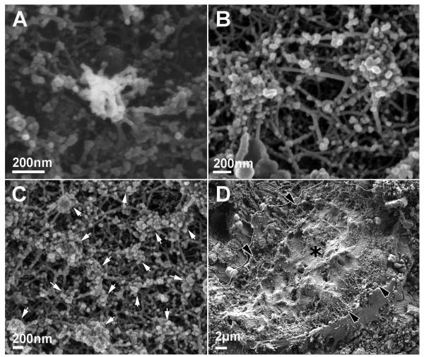
The isolated podosome is structurally characterized by a dense, fibrous actin core (~300-400nm in diameter, and ~1-4μm high), composed of fibers oriented more or less perpendicular to the membrane, and sparser actin fibers connected to the core and anchored to the membrane.[11] This structure was observed on all three substrates we examined (Fig. 3A; Supp. Fig. S1A). The same holds true for clusters of podosomes (Fig. 3B; Supp. Fig. S1B).
Figure 3.
Ventral membrane of osteoclast on calcite. A) Individual podosome. B) Podosome cluster. C) Sealing zone. This structure is built of podosomes (arrows). D) Ventral membrane of a whole cell. The cell boundary on the upper left is highlighted for clarity. The sealing zone is marked by black arrowheads, and the ruffled border, with a black asterisk.
In the sealing zone, distinct podosomes can be detected as the building blocks forming the structure on all substrates. Apart from the actin fibers connecting the podosome core to the membrane, other fibers are observed which connect the cores of different podosomes at all heights (Fig. 3C; Supp. Fig. S1C, E). The architecture of the sealing zone is similar on calcite (Fig. 3C, D) and bone (Supp. Fig. S1E, F) both in width (3-6μm) and in the average distance between neighboring podosome cores (250±60nm on calcite and 220±50nm on bone). On glass, however, the sealing zone-like structure is about 2μm wide, and is roughly half as dense, with an average distance between podosomes of 500±140nm (Supp. Fig. S1C, D). Nevertheless, the basic building blocks, the podosomes, and the manner in which they are interconnected remain the same, regardless of the substrate.
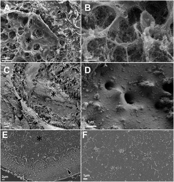
While the individual podosome, podosome cluster, and sealing zone share the same basic architecture on all substrates examined, there are marked differences in the membrane structure delimited by the sealing zone (the so-called ruffled border). Exposure of the ventral membrane of osteoclasts adhering to glass reveals flat membranes in the area delimited by the sealing zone-like structure (Fig. 4E, F).
Figure 4.
A, B) Ruffled border on bone, delimited by sealing zone, with a highly convoluted membrane. C, D) Ruffled border on calcite, delimited by sealing zone, with sparse extrusions. Note how the membrane follows the topography of the surface. E, F) A flat membrane delimited by the sealing zone on glass, where the ruffled border should be.
Sealing zones and sealing zone-like structures are marked by arrows, and the ruffled border, by asterisks.
On bone, the ruffled border appears in transmission electron microscopy (TEM) sections as finger-like structures delimited by membrane folds.[5, 24, 25] In agreement with these observations, SEM observation of ventral membranes obtained after removal of the cell body shows cylindrical extrusions emanating from the membrane, with typical diameters of 1-2μm, which almost entirely cover the area delimited by the sealing zone (Fig. 4A). These channel-like extrusions contain fibers (presumably composed of actin) supporting the structure (Fig. 4B).
On calcite, some deep extrusions are also observed, but they are fewer than those seen on bone, and more dispersed (Fig. 4D). Apart from these features, the membrane appears to follow the topography of the surface, remaining flat where the etching is shallower, and coating the spikes typical of calcite resorption pits in the areas where such pits have formed (Fig. 4C, D).
Actin reorganization dynamics
A collection of static frames of resorbing osteoclasts cannot provide a full description of osteoclast activity on the different substrates. In particular, it is incapable of providing information on the dynamics underlying the formation of the resorption apparatus, and its stability. Such information was provided by taking time-lapse movies of live cells on the different substrates.
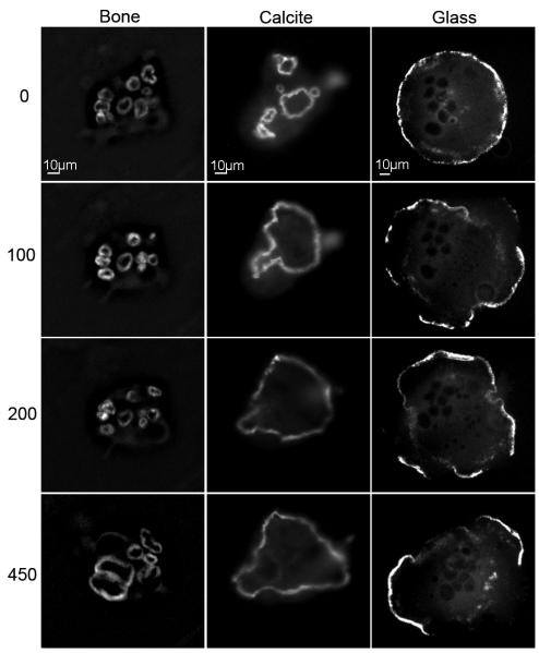
Accordingly, differentiated cells stably expressing GFP-actin were plated on the substrates, and monitored over the course of two days. (The presence of GFP does not influence cell activity and actin dynamics.[26]) Frames were collected at a frequency of one frame per minute: typical movies are shown in the Supplementary Material (Supp. Movies S1, 2 and 3). Representative frames from these movies, recorded at time points 0, 100 min, 200 min, and 450 min, are presented in Fig. 5.
Figure 5.
Sealing zone on bone and calcite, and sealing zone-like structure on glass, viewed at the following time points: 0, 100, 200 and 450 minutes. The initial time point is arbitrary. Notice the fragility of the rings on glass, in comparison to the coherent rings on bone and calcite. Notice the stability of the small rings on bone, in comparison to the stable, large ring on calcite.
The dynamics of actin reorganization in cells plated on glass, calcite and bone are dramatically different. On glass, the podosome belt is typically fragmented, with 79±20% (n=178) of the rings/cell being incompletely formed; i.e., displaying gaps of at least 4 μm. The typical dynamic picture consists of the formation of rings emerging from within the cell, merging with each other, and moving to the cell periphery. There, the rings, or fragments of rings, are stable for only a few minutes before they collapse (Fig. 5, right panels; Supp. Movie S3).
In contrast to glass, osteoclasts plated on calcite or bone form continuous rings: the percentage of fragmented rings per cell observed on calcite is 15±9% (n=263), and on bone, 12±8% (n=300) (Fig. 5).
On calcite, small rings merge together to form one or two large rings, usually at the periphery of the cell, which maintain their stability over several hours (Fig. 5, central panels; Supp. Movie S2). Osteoclasts plated on bone form several small, very stable rings within one cell: these, too, last for several hours as individual rings, adjoining each other without fusing (Fig. 5, left panels; Supp. Movie S1). These small, stable rings, lying in close proximity to one another, most likely correspond to the partitions observed within the pits on bone (Fig. 2B). Moreover, rings that have disassembled frequently reform in the same positions, while in other locations within the limits of the cell, rings never form. This finding indicates that osteoclasts recognize certain areas of the bone surface, within the overall area covered by a single cell, which are more prone than others to resorption. In contrast to bone, on the homogenous surfaces of calcite and glass the rings usually encompass the entire cell area.
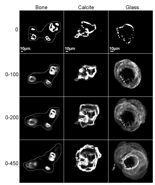
The differences in osteoclast behavior are summarized in Fig. 6, where all sequential frames from each movie recorded on bone, calcite and glass were superimposed, according to time periods 0, and ranging from 0-100, 0-200, and 0-450 minutes. Preferential osteoclast activity in selected areas is clear (Fig. 6, left panels) on bone, where the central area subtended by the cell failed to support formation of rings during more than seven hours. The osteoclast plated on calcite (Fig. 6, central panels) formed distinct rings, each of which was active for the first two hours. These rings subsequently fused, such that during the next three to seven hours, one large ring was stably located at the periphery of the cell. The podosome belt formed by the osteoclast on the glass surface (Fig. 6, right panels) was very mobile, as demonstrated by the “cloudy” appearance of the superimposed images, indicating that all the positions in a centrifugal location relative to the initial fragmented ring were visited, each for a very short time.
Figure 6.
Sealing zones on bone and calcite, and a sealing zone-like structure on glass. Frames from 450-minute movies were superimposed, such that the last frame is composed of 450 images. The intensity represents stability. On bone, the borders of the cell are drawn on the picture. Notice that some areas are constantly being visited by rings, while others are not. On calcite and glass, the borders of the cell are delimited by the rings. Notice the difference between calcite and glass: on both, the rings travel to the cell periphery, but on calcite, the rings are very stable, while on glass, unstable rings lasting for a short time cover the entire cell.
Discussion
The primary issue raised in this work is whether – and, if so, how – osteoclasts sense the substrate to which they are attached; moreover, how the signals originating from the substrate are translated into different features of osteoclast activity. We demonstrate herein that though osteoclasts adhering to glass, calcite single crystals, and bone share common characteristics, they also differ in certain critical ways. While the fundamental architecture of sealing zones or sealing zone-like structures, consisting of podosomal subunits linked together by a robust actin fiber network, is common to cells attached to all three substrates, the ruffled border zone is markedly different. Moreover, the integrity, stability and dynamic behavior of the podosomal super-structures fundamentally differ in osteoclasts cultured on these substrates.
The use of calcite, in particular enabled us to reach conclusions that go beyond direct comparison of osteoclast behavior on conventional surfaces such as glass and bone. Calcite was previously reported to be an unfavorable substrate for osteoclast adhesion,[19] yet coating it with the adhesion protein vitronectin dramatically improved the viability and activity of osteoclasts on its surface. Vitronectin adsorption does not modify the nature or the topography of the surface, but only affects the availability and density of attachment sites, which are always mediated by adhesion proteins. Furthermore, there is evidence that the topography of the calcite surface itself dramatically influences osteoclast behavior, independent of vitronectin adsorption (Geblinger et al., manuscript in preparation). We note that the amount of vitronectin on the surface cannot be the limiting factor causing different osteoclast behavior on calcite, glass and bone. Vitronectin is present in excess in the serum used to culture the cells, and is known to be strongly adsorbed on glass. Moreover, in experiments carried out with and without preincubation of glass and bone with vitronectin none of the static or dynamic properties monitored here was observed to be different (data not shown).
The fact that the architecture of the basic adhesion unit (i.e. the podosome) is similar in cells growing on glass, calcite and bone, suggests that the assembly of this structure in osteoclasts is intrinsically regulated, irrespective of the particular adhesive surface used. However, further development of podosomal super-structures is surface-sensitive. The fluorescence intensity of podosome-associated actin in the sealing zones formed on bone and calcite is higher than that formed on glass, reflecting the nearly double podosome density measured here and, most likely, also a greater height in the actin core bundle,[27] and increased numbers of interconnecting fibers. Moreover, the sealing zones formed on calcite and bone are about twice as wide as the sealing zone-like structure formed on glass. The reasons for these differences are not clear, yet it is tempting to relate them to the fact that bone and calcite are resorbable, calcium-rich surfaces, while glass is not. Thus, part of the regulation of sealing zone formation, integrity and dynamics may be related to acidification of the lacuna cavity and its neutralization upon mineral dissolution on bone and calcite, but not on glass.
Despite the apparent similarity of the sealing zone structure in osteoclasts growing on bone and calcite, there are some intriguing differences between the two. Examination of the area along the ventral cell membrane, which is delimited by the sealing zone, reveals multiple, finger-like structures supported by a dense actin fiber network in cells growing on bone; (Fig. 4A, B and ref[28, 29]) similar structures were sparser in cells cultured on calcite (Fig. 4C, D), and entirely absent on glass (Fig. 4E, F). Differences in the ruffled border structure induced by calcite and bone do not, however, affect the ability of the cells to degrade the surface. The amount, size and shape of the pits, on the other hand, are determined not only by the activity of the cells, but also by the nature of the substrate. The nature of the mineral and its solubility, the surface area of the crystals and the presence of organic matrix, all affect resorption kinetics and the resulting pit architecture.
Dynamic analysis of intrinsically fluorescent actin revealed major differences in sealing zone formation, its development and turnover. The adhesion structures of osteoclasts cultured on glass, in the form of incomplete rings, were highly dynamic, displaying repeated cycles of rapid, somewhat erratic centrifugal movement towards the cell periphery. On calcite, ring fusion was also detected, yet after initial merging and outward migration, the rings became stable for several hours at the cell periphery. On bone, small sealing zone rings were also found to be stable for several hours. Notably, the ring-mediated contact of osteoclasts with the bone surface is restricted to specific regions of the cell, while in other locations beneath the same cell, rings did not form (Fig. 5, 6).
The existence of adhesion-promoting and adhesion-excluding domains is most likely related to the heterogeneity of the bone surface; therefore, attempts to correlate between those features are currently underway. In particular, we aim to define the specific local characteristics – such as chemical nature, physical properties and topography – of the various regions on the bone surface, that could underlie the observed differences in osteoclast behavior.
Conclusions
This study, addressing the organization and dynamics of the resorption apparatus of osteoclasts growing on three different surfaces, yielded novel information on cell-autonomous and surface-induced regulation of podosome formation, organization and dynamics. Examination of actin organization in podosomal super-structures, and actin dynamics, highlighted the ability of osteoclasts to sense the local properties of the underlying substrate and respond to these signals both locally, affecting adhesion sites directly, and globally, by activating signaling pathways that regulate cellular activity.
Experimental Section
Tissue culture and substrate preparation
RAW 264.7 cells were from the American Type Culture Collection (ATCC) (Manassas, VA, USA). To induce osteoclast differentiation, cells were cultured on plastic dishes (100 cells/mm2) in alpha MEM with Earle's salts, L-glutamine and NaHCO3 (Sigma Chemical Co., St. Louis, MO, USA) supplemented with fetal bovine serum (FBS) (10%) (Gibco, Grand Island, NY, USA), antibiotics (Biological Industries, Beit Haemek, Israel), recombinant soluble receptor activator of NFκB ligand (RANK-L) (20 ng/ml), and macrophage colony-stimulating factor (M-CSF) (20 ng/ml) (R&D, Minneapolis, MN, USA), at 37 °C in a 5% CO2 humidified atmosphere for 3 days. Once differentiated, the cells were removed with EDTA (10 mM) for 10 min, and then plated for 60 hrs on thin slices of bone, calcite, and glass cover slips.
Longitudinal bone slices, 5-10 mm wide and 0.5-1 mm thick, were mechanically sawed from cattle femur, immersed in ethanol (70%) for 10 min, and kept in medium and serum to avoid drying of the bone prior to cell plating.
Calcite single crystal slices, 5-10mm wide and 0.5-1mm thick, were mechanically sawed from a geological crystal (WARD'S Natural Science, Rochester, NY, USA) at an angle that differed from the stable cleavage plane, thus creating a surface with multiple steps. Slices were immersed in ethanol (70%) for 10 min and kept overnight at 4°C, with or without vitronectin (10μg/ml) (Sigma). Prior to plating, slices were washed, placed in the culture medium, and heated to 37°C.
Ventral membrane preparation for SEM microscopy
To characterize the adhesive structures in a cellular environment, we developed a sample preparation technique involving high-resolution, three-dimensional electron microscopy (Anderson, Page, Beck, Nickell, Volkmann and Hanein, manuscript in preparation). The procedure, which we termed ventral membrane preparation (VMP), constitutes an adaptation of published procedures[30, 31], and entails unroofing of the cell's basal portion, while preserving the components' three-dimensional organization and immunogenicity. For the SEM samples, cells underwent VMP and were immediately fixed with warm gluteraldehide (GA) (2%) (EMS, Hatfield, PA, USA) in PBS for 30 min. Cells were then washed 3 times for 5 min in PBS, and twice for 5 min with cacodylate buffer (0.1MCaCO, 5mMCaCl pH7.3) (Merck, Darmstadt, Germany), post-fixed with OsO4 (1%) (EMS) for 45 min, washed 3 times in cacodylate buffer, and then twice with H2O. The preparations were then incubated with tannic acid (1%) (Merck, Darmstadt, Germany) for 5 min, washed 3 times in H2O, incubated with uranyl acetate (1%) (EMS) for 30 min, and washed 3 times with H2O. Dehydration in increasing concentrations of reagent-grade ethanol (2×5 min for 25%, 50%, 70%, and 95% concentrations, and 2×10 min for 100% concentration) was followed by critical point drying, using CPD30 (BAL TEC AG,Balzers, Liechtenstein), coated with 1–2 nm Cr using K575X (Emitech, Kent, UK). Samples were visualized in the SEM LEO-Supra 55 VP FEG (Zeiss, Oberkochen, Germany), and in the high-resolution SEM Ultra 55 (Zeiss). For bone and calcite slices, the procedure was the same as that used for glass, excluding incubation of the slices with uranyl acetate.
Micromanipulation and electron microscopy under wet conditions were conducted and observed in the FESEM XL30 (Philips, Hillsboro, OR, USA).
Fluorescence microscopy
For live cell imaging, RAW cells stably expressing GFP-actin[32] were induced to differentiate in plastic dishes, and then plated on bone slices, calcite slices and glass cover slips, as described above. Cells were simultaneously plated on several slices to enable their observation for 60 hrs; samples were replaced every 8-12 hrs. The first sample was observed 3-4 hrs after replating. Bone and calcite surfaces were observed in medium and serum by attaching the fragments upside-down to a glass-bottomed Petri dish. All image analyses were carried out using Priism software for Linux operating systems (http://msg.ucsf.edu/IVE/Download/). Data were acquired at 37°C with a DeltaVision system (Applied Precision Inc., Issaquah, WA, USA), consisting of an inverted microscope IX70 equipped with a 20x/0.7 objective (Olympus, Tokyo, Japan).
For Fig 6 preparation, the images were smoothed (3 pixel box filter) to reduce noise, flattened (high pass filter) and thresholded to define the rings. The resulted binary images for the time sequences were then summed.
Supplementary Material
Acknowledgments
We would like to thank Dr. Chen Luxenburg for help, guidance and fruitful discussions, Dr. Eugenia Klein for assistance with the SEM imaging, Prof. Zvi Kam for help in image processing and Barbara Morgenstern for help in preparing this article for publication. This study was supported by a grant from the Israel Science Foundation, and an NIGMS grant to the Cell Migration Consortium (NIH Grant U54GM64346). Electron microscopy studies were conducted at the Irving and Cherna Moskowitz Center for Nano and Bio-Nano Imaging at the Weizmann Institute of Science. B.G. holds the Erwin Neter Professorial Chair in Cell and Tumor Biology L.A holds the Dorothy and Patrick E. Gorman Professorial Chair of Biological Ultrastructure.
References
- 1.Meunier PJ, Boivin G. Bone. 1997;21:373–377. doi: 10.1016/s8756-3282(97)00170-1. [DOI] [PubMed] [Google Scholar]
- 2.Weiner S, Wagner HD. Annual Review of Materials Science. 1998;28:271–298. [Google Scholar]
- 3.Weiner S, Traub W, Wagner HD. J Struct Biol. 1999;126:241–255. doi: 10.1006/jsbi.1999.4107. [DOI] [PubMed] [Google Scholar]
- 4.Roodman GD. Endocr Rev. 1996;17:308–332. doi: 10.1210/edrv-17-4-308. [DOI] [PubMed] [Google Scholar]
- 5.Mulari M, Vaaraniemi J, Vaananen HK. Microsc Res Tech. 2003;61:496–503. doi: 10.1002/jemt.10371. [DOI] [PubMed] [Google Scholar]
- 6.Blair HC. Bioessays. 1998;20:837–846. doi: 10.1002/(SICI)1521-1878(199810)20:10<837::AID-BIES9>3.0.CO;2-D. [DOI] [PubMed] [Google Scholar]
- 7.Baron R. Anatomical Record. 1989;224:317–324. doi: 10.1002/ar.1092240220. [DOI] [PubMed] [Google Scholar]
- 8.Linder S, Aepfelbacher M. Trends Cell Biol. 2003;13:376–385. doi: 10.1016/s0962-8924(03)00128-4. [DOI] [PubMed] [Google Scholar]
- 9.Buccione R, Orth JD, McNiven MA. Nature Reviews Molecular Cell Biology. 2004;5:647–657. doi: 10.1038/nrm1436. [DOI] [PubMed] [Google Scholar]
- 10.Marchisio PC, Cirillo D, Naldini L, Primavera MV, Teti A, Zamboninzallone A. Journal of Cell Biology. 1984;99:1696–1705. doi: 10.1083/jcb.99.5.1696. [DOI] [PMC free article] [PubMed] [Google Scholar]
- 11.Luxenburg C, Geblinger D, Klein E, Anderson K, Hanein D, Geiger B, Addadi L. PLoS ONE. 2007;2:e179. doi: 10.1371/journal.pone.0000179. [DOI] [PMC free article] [PubMed] [Google Scholar]
- 12.Vaananen HK, Horton M. J Cell Sci. 1995;108(Pt 8):2729–2732. doi: 10.1242/jcs.108.8.2729. [DOI] [PubMed] [Google Scholar]
- 13.Henriksen K, Leeming DJ, Byrjalsen I, Nielsen RH, Sorensen MG, Dziegiel MH, Martin TJ, Christiansen C, Qvist P, Karsdal MA. Osteoporos Int. 2007;18:751–759. doi: 10.1007/s00198-006-0298-4. [DOI] [PubMed] [Google Scholar]
- 14.webster TJ. Scripta mater. 2001;44:1639–1642. [Google Scholar]
- 15.Nakamura I, Takahashi N, Sasaki T, Jimi E, Kurokawa T, Suda T. J Bone Miner Res. 1996;11:1873–1879. doi: 10.1002/jbmr.5650111207. [DOI] [PubMed] [Google Scholar]
- 16.Shimizu H, Sakamoto S, Sakamoto M, Lee DD. Bone Miner. 1989;6:261–275. doi: 10.1016/0169-6009(89)90033-0. [DOI] [PubMed] [Google Scholar]
- 17.Kurata K, Uemura T, Nemoto A, Tateishi T, Murakami T, Higaki H, Miura H, Iwamoto Y. J Bone Miner Res. 2001;16:722–730. doi: 10.1359/jbmr.2001.16.4.722. [DOI] [PubMed] [Google Scholar]
- 18.Wenisch S, Stahl JP, Horas U, Heiss C, Kilian O, Trinkaus K, Hild A, Schnettler R. J Biomed Mater Res A. 2003;67:713–718. doi: 10.1002/jbm.a.10091. [DOI] [PubMed] [Google Scholar]
- 19.Monchau F, Lefevre A, Descamps M, Belquin-myrdycz A, Laffargue P, Hildebrand HF. Biomol Eng. 2002;19:143–152. doi: 10.1016/s1389-0344(02)00023-0. [DOI] [PubMed] [Google Scholar]
- 20.Ramaswamy Y, Haynes DR, Berger G, Gildenhaar R, Lucas H, Holding C, Zreiqat H. J Mater Sci Mater Med. 2005;16:1199–1205. doi: 10.1007/s10856-005-4729-0. [DOI] [PubMed] [Google Scholar]
- 21.Doi Y, Iwanaga H, Shibutani T, Moriwaki Y, Iwayama Y. J Biomed Mater Res. 1999;47:424–433. doi: 10.1002/(sici)1097-4636(19991205)47:3<424::aid-jbm19>3.0.co;2-0. [DOI] [PubMed] [Google Scholar]
- 22.Leeuwenburgh S, Layrolle P, Barrere F, de Bruijn J, Schoonman J, van Blitterswijk CA, de Groot K. J Biomed Mater Res. 2001;56:208–215. doi: 10.1002/1097-4636(200108)56:2<208::aid-jbm1085>3.0.co;2-r. [DOI] [PubMed] [Google Scholar]
- 23.Salo J, Lehenkari P, Mulari M, Metsikko K, Vaananen HK. Science. 1997;276:270–273. doi: 10.1126/science.276.5310.270. [DOI] [PubMed] [Google Scholar]
- 24.Lakkakorpi PT, Vaananen HK. Microsc Res Tech. 1996;33:171–181. doi: 10.1002/(SICI)1097-0029(19960201)33:2<171::AID-JEMT7>3.0.CO;2-W. [DOI] [PubMed] [Google Scholar]
- 25.Mulari MT, Zhao H, Lakkakorpi PT, Vaananen HK. Traffic. 2003;4:113–125. doi: 10.1034/j.1600-0854.2003.40206.x. [DOI] [PubMed] [Google Scholar]
- 26.Destaing O, Saltel F, Geminard JC, Jurdic P, Bard F. Mol Biol Cell. 2003;14:407–416. doi: 10.1091/mbc.E02-07-0389. [DOI] [PMC free article] [PubMed] [Google Scholar]
- 27.Jurdic P, Saltel F, Chabadel A, Destaing O. Eur J Cell Biol. 2006;85:195–202. doi: 10.1016/j.ejcb.2005.09.008. [DOI] [PubMed] [Google Scholar]
- 28.Akisaka T, Yoshida H, Suzuki R. J Electron Microsc (Tokyo) 2006;55:53–61. doi: 10.1093/jmicro/dfl012. [DOI] [PubMed] [Google Scholar]
- 29.Kato T, Akisaka T. J Anat. 1994;185(Pt 3):599–607. [PMC free article] [PubMed] [Google Scholar]
- 30.Nermut MV, Eason P, Hirst EMA, Kellie S. Experimental Cell Research. 1991;193:382–397. doi: 10.1016/0014-4827(91)90111-7. [DOI] [PubMed] [Google Scholar]
- 31.Avnur Z, Geiger B. Journal of Molecular Biology. 1981;153:361–379. doi: 10.1016/0022-2836(81)90283-7. [DOI] [PubMed] [Google Scholar]
- 32.Luxenburg C, Parsons JT, Addadi L, Geiger B. Journal of Cell Science. 2006;119:4878–4888. doi: 10.1242/jcs.03271. [DOI] [PubMed] [Google Scholar]
Associated Data
This section collects any data citations, data availability statements, or supplementary materials included in this article.


