Abstract
Shape memory polymers (SMPs) are smart materials that can remember a primary shape and can return to this primary shape from a deformed secondary shape when given an appropriate stimulus. This property allows them to be delivered in a compact form via minimally invasive surgeries in humans, and deployed to achieve complex final shapes. Here we review the various biomedical applications of SMPs and the challenges they face with respect to actuation and biocompatibility. While shape memory behavior has been demonstrated with heat, light and chemical environment, here we focus our discussion on thermally stimulated SMPs.
1. Introduction
The ability of SMPs to recover a primary shape from a stable temporary form when exposed to a specific stimulus (e.g., heat) has spurred the development of various SMP-based medical devices.1–3 They form an attractive area of research and several excellent reviews have been published on SMPs.4–11 Their large recovery strains (>300%) and low recovery stresses (~1 to 10 MPa) extend their application relative to shape memory alloys (SMAs), which possess much lower recovery strains (<8%) and higher recovery stresses (~1000 MPa). In addition to shape memory, SMPs possess other characteristics that have triggered their investigation in the medical field. One such characteristic is biocompatibility,12–17 which opens the door to the arena of implantable SMP devices. Another characteristic is tunable actuation temperature (e.g., glass transition temperature of thermally responsive SMPs) and glassy elastic modulus. By modifying the chemical composition,18,19 the thermomechanical properties of SMPs can be tailored for specific applications. For example, thermally responsive SMPs with a glass transition temperature below 37 °C are more compliant (i.e., have a lower glassy elastic modulus and recovery force) and self-actuate at body temperature, while SMPs with a higher glass transition temperature accompanied by an extrinsic heating source provide higher recovery force and explicit control of the actuation. In addition, the ability to formulate SMP porous foams broadens the range of potential volume-filling applications. Apart from their thermomechanical, chemical, and structural properties, the relatively inexpensive fabrication of SMPs into complex shapes via extrusion, casting, or machining opens the possibility of custom patient-specific device geometries. This review describes promising biomedical applications of SMP, citing specific examples from the literature, in cardiovascular, tissue engineering, and other specialized fields.
2. Principles of thermally activated SMPs
Thermally actuated shape memory polymers exhibit a characteristic transition temperature, Ttrans, above which they can be deformed to a secondary shape from a primary shape by application of external stress. The deformed shape can then be fixed by cooling the polymer below Ttrans and then removing the deformation stress. Recovery to the primary shape can subsequently be achieved by heating the polymer above Ttrans. The earliest known review of SMPs was published as a technical report by the Canadian government.20
Polymer chains prefer to be in a randomly coiled arrangement which defines their primary shape.21 If they are deformed from this shape while they are mobile (above Ttrans), they tend to return to the primary shape due to the entropic gain in returning to the random/disordered arrangement. However, the polymer chains may find a new equilibrium state in the deformed shape and/or might not recover the original shape completely, as there is no one preferred random configuration (the phenomenon of new shape forming or secondary shape forming22). The physical entanglements between long polymer chains act as netpoints to avoid new shape forming and assist in a more complete recovery to the primary shape. Polynorbornene based SMPs have been shown to recover their primary shape mainly based on chain entanglements.23 Hydrogels have been shown to be thermally activated by melting crystallized side chain above Ttrans.24,25 By the same principle, chemical crosslinks (as in polyethylene based SMPs26,27) and physical crosslinks (as in polyurethane28 and styrene–butadiene copolymer based SMPs29) in the polymer help it memorize its primary shape and assist in primary shape recovery.6
Above Ttrans the polymer chains will return to their primary state on removing the deformation stress or adapt to the deformed shape if kept too long under deformation. Therefore, in order to keep the polymer fixed in its deformed shape and preserve shape memory, it must be secured in this shape by prohibiting chain mobility. This can be done by kinetically freezing the deformed structure below the glass transition temperature (Tg) of the polymer where the polymer is in its glassy state and the chains do not have any energy to return to their preferred arrangement. This process applies to polynorbornene and polyurethane based chemistries.6 Alternatively, the deformed shape can be fixed by introduction of reversible physical crosslinks that restrain the chain motion. These physical crosslinks are based on hydrogen bonding and the crystalline segments thus formed in the polymer. This process applies to polyethylene, trans-polyisoprene, and styrene–butadiene copolymer based SMPs.6 The different phases demix and crystallization of one phase generates the netpoints of the physical crosslinks keeping the chains immobile. On heating above the melting temperature of the crystallites (Tm), these physical crosslinks (crystallites) melt away and the primary shape is recovered due to entropic favourability. The extent of shape memory has been shown to be directly linked to the extent of phase separation, which is an indirect indication of the degree of crystallites/physical crosslinks formed in the polymer.9 While numerous shape memory polymers based on Tg or Tm based activation have been reported, there has also been an investigation of “triple shape” polymers that show both Tg and Tm or two Tm based shape memory transitions successively in the same polymer.30
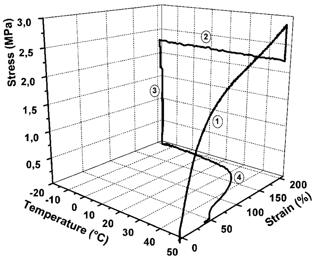
The shape memory behaviour can be studied on a macroscopic level by performing a thermomechanical cycle on the material. Thermomechanical studies of shape memory polymers have been published.31–34 There are 4 steps associated with this cycle as shown in Fig. 1.4 (1) Deformation: while it is above the Ttrans, SMP material is first deformed to a temporary shape from the primary shape. This deformation introduces strain in the material, and also increases the material stress. The stress originates from the increase in the stored energy of the material due to decrease in the entropy of polymer chains as the chains become more aligned. (2) Fixing: the material is cooled below Ttrans. This fixes the temporary shape, and the stress in the material decreases indicating decrease in the movement of polymer chains below Ttrans. (3) Unloading: the external deformation force is removed after the temporary shape gets fixed. As long as the material is below Ttrans it retains the deformed shape in this stage. (4) Recovery: the material is heated above Ttrans. Primary shape is recovered owing to resumption of movement in chains in the presence of supplied thermal energy.
Fig. 1.
Cyclic thermomechanical experiment of polyurethane synthesized from the reaction of 35 wt% oligo(p-dioxanone) diol and 65 wt% oligo(ε-caprolactone) diol with 2,2(4),4-trimethylhexanediisocyanate. It shows a Ttrans of 40 °C. Results of the first cycle are shown. Step 1 of the experiment is strain-controlled; steps 2 through 4 to beginning of next cycle are stress-controlled. (Reprinted with permission from A. Lendlein and R. Langer, Biodegradable, elastic shape-memory polymers for potential biomedical applications, Science, 2002, 296, 1673.12)
Quantitatively, the ability to fix the deformed shape and the ability to recover the primary shape are defined as Rf (%) = εu/εm × 100 and Rr(%) = (εu − εp)/(εm − εp) × 100 respectively, where εu, εp and εm represent the fixed strain after unloading, the permanent strain after heat-induced recovery, and the temporal strain achieved by deformation.11 The fastest recovery for SMPs is seen near the Ttrans of the material. The sharpness of this shape memory recovery is an important indicator of shape memory behaviour and is being investigated by researchers.35 Since both shape fixity and shape recovery are critical in estimating the quality of the shape memory of a material, an all-inclusive parameter, SM fill factor, was coined by Liu et al.5 This factor classifies the shape memory materials in five categories: (a) ideal, (b) high shape fixing and shape recovery but finite sharpness, (c) high shape recovery but poor shape fixing, (d) high shape fixing but poor shape recovery and (e) poor shape fixing and recovery, with a fill factor of 1 for ideal SMP (a) and 0 for poor SMP (e). Liu et al. demonstrated a relatively good shape memory with a fill factor of 0.647 on a previously developed covalently cross-linked polymer network.36
3. Methods of heating for actuation
Thermally actuated SMPs must be heated above their characteristic transition temperature (Ttrans) to induce their shape change. For SMPs with Ttrans close to body temperature, actuation can be accomplished simply by placing the SMP into the body and allowing heat transfer from the adjacent fluid or tissue to induce actuation. However, in some cases a higher Ttrans may be desired, providing more mechanical rigidity to the SMP (i.e., higher elastic modulus) at body temperature as well as explicit control of the actuation. The addition of dopants or fillers to the SMP has enabled several heating schemes using external energy sources to selectively heat the SMP. From a safety standpoint, heat transfer from the SMP to the adjacent fluid and tissue must be addressed when such schemes are used.
Inclusion of appropriate dopants has enabled the use of light, electric current, and magnetic fields to achieve selective heating of the SMP for thermal actuation. Small et al. demonstrated photothermal actuation using IR laser light.37–39 The SMP was doped with a laser-absorbing dye to selectively heat the SMP. Electroactuation has been studied by several investigators via resistive Joule heating of SMP composites using conductive fillers like polypyrrole, carbon fibers, carbon black, carbon nanotubes, and Ni particles.40–43 Although the fillers tend to reduce the shape fixity and the strain limit for deformation, their use demonstrates an attractive method of heating via electric current, as well as improving thermal conductivity for actuation at body temperature.
Inductive heating using an applied magnetic field and magnetic fillers like terfenol-D, ferric-oxide/silica particles, Ni–Zn ferrite particles and magnetite particles in the SMP has also been demonstrated.44–51 Impressive 98–118% shape fixity with ~91% shape recovery was shown by Mohr et al. using ferrite/Si particles as fillers.48 Heating achieved via this method can be due to hysteresis loss as well as resistive heating via eddy currents generated in the system. However, the restrictive window of clinically usable frequencies (50–100 kHz) limits the increase in temperature and the shape recovery that can be presently achieved with this mechanism.50
Solvent based actuation of SMPs has been demonstrated, in which the solvent depresses the glass transition temperature of the material via plasticization and/or disruption of the hydrogen bonding and hence the crystalline netpoints that fix the secondary shape of the polymer.46,52–54 Therefore, actuation can be achieved at ambient temperature. Depending on the geometric shape of the device, the rate of primary shape recovery may vary due to variation in the rate of penetration of the solvent into the SMP. This technique is feasible for deployment of SMP medical devices in body fluids.
4. Biocompatibility of SMPs
Many research groups are pursuing medical applications of SMPs. Two of the earliest reports on biomedical SMP applications also contained some data indicating good biocompatibility.12,55 As Dietsch and Tong present in their review, which includes a historical review of polymers engineered for SMP properties, there are few SMPs that are currently commercially available.6 Thus, without a supplier of medical-grade SMPs, the burden of establishing biocompatibility currently falls on medical device start-up companies, academic groups, and government laboratories. Early biocompatibility data follow expected results of non-shape-changing biomedical applications of polymers that are documented in many journals and texts.56 For example, the first commercially available SMPs from Mitsubishi Heavy Industries, Ltd. (Nagoya, Japan), which are now distributed through a subsidiary (DiAPLEX, Ltd.), are polyurethane SMPs. A significant number of the early published biocompatibility studies have focused on the DiAPLEX materials where good biocompatibility has been documented: low cytotoxicity,13,55,57 low thrombogenicity,14 low platelet activation,13,14 low cytokine activation,14 and low in vivo inflammatory response.55 These results are generally expected from the polyurethane literature.56,58 In addition to the DiAPLEX materials, other published biocompatibility studies on SMPs include poly(l-lactide)-polyurethanes,15 poly(ε-caprolactone)dimethacrylate,17 and copolymerized methyl methacrylate and poly-(ethylene glycal)dimethacrylate.16,59
5. Proposed biomedical applications
5.1 Endovascular stroke treatment
Development of SMP-based devices for use in minimally invasive, X-ray fluoroscopically guided, catheter-based interventional procedures has increased over the last decade. Examples of SMP endovascular devices developed to enhance interventional stroke treatment procedures, including clot removal devices, aneurysm occlusion devices, and vascular stents, are described.
5.1.1 Clot removal devices
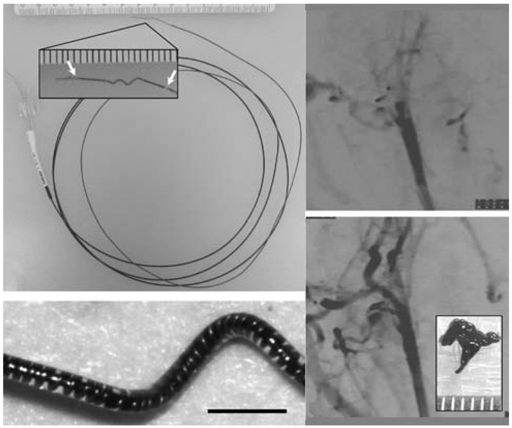
Thermally activated SMP-based mechanical clot extraction devices to treat ischemic stroke was reported by Maitland et al.60 These devices were designed to be delivered through a catheter and penetrate the clot in a narrow form, and then actuate into a clot-grabbing form for clot extraction. Maitland et al.60 demonstrated photothermal actuation of corkscrew-shaped and umbrella-shaped devices by coupling light from a diode laser operating at a wavelength of 810 nm into the SMP device. The SMP was doped with a laser-absorbing dye to achieve selective heating of the device. Metzger et al.61 showed that the SMP corkscrew device could hold a blood clot against vascular physiological forces in vitro. Characterization of the photothermal actuation of the SMP corkscrew device and demonstration of a clot extraction procedure in an in vitro vascular occlusion model was reported by Small et al.38,39 To enhance the recovery force compared to a pure SMP device, the group devised a resistively heated hybrid corkscrew device consisting of a shape memory nickel–titanium alloy (nitinol) wire core encapsulated in a SMP shell.62 Hartman et al.63 demonstrated fluoroscopically guided clot removal using the hybrid device in an in vivo rabbit acute arterial occlusion model (Fig. 2).
Fig. 2.
(Top left) Electromechanical embolectomy device in its corkscrew form. The SMP-nitinol corkscrew microactuator is mounted at the distal end of a microcatheter. Ac lose-up of the microactuator showing the radio-opaque gold markers (arrows) is seen in the inset (scale divisions in millimetres). (Bottom left) Microscope image of the microactuator showing the copper-wound nitinol wire encapsulated by the SMP. Scale bar = 1 mm. (Top right) Angiogram showing occlusion of the rabbit common carotid artery. (Bottom right) Post-treatment angiogram showing complete restoration of blood flow. A photograph of the retrieved clot is shown in the inset (scale divisions in millimetres). (Reprinted with permission from J. Hartman, W. Small, IV, T. S. Wilson, J. Brock, P. R. Buckley, W. J. Benett, J. M. Loge and D. J. Maitland, Embolectomy in a rabbit acute arterial occlusion model using a novel electromechanical extraction device, Am. J. Neuroradiol., 2007, 28, 872.63)
5.1.2 Aneurysm occlusion devices
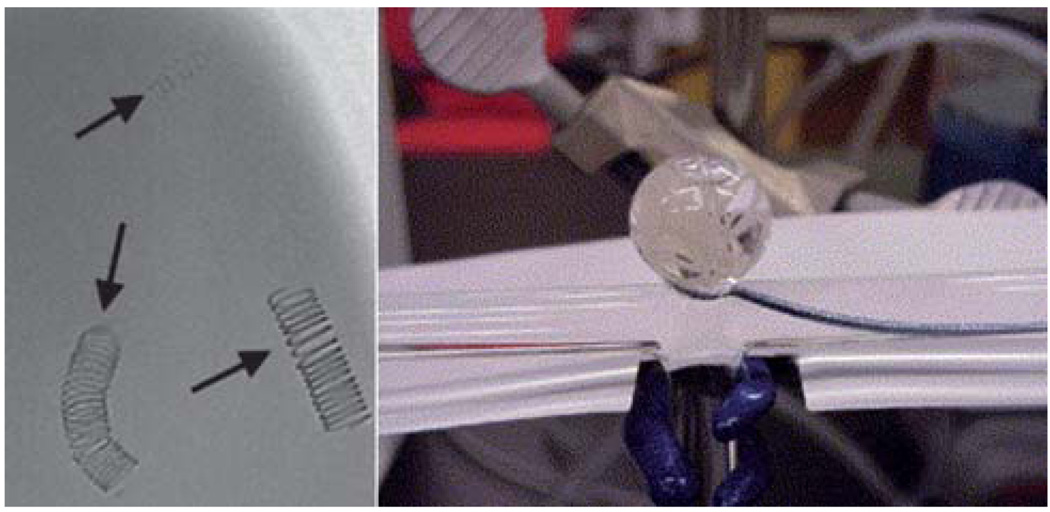
One criticism of endovascular therapy with current devices based on the Guglielmi detachable coil (GDC) is that a significant proportion of treated aneurysms will require repeat treatment due to compaction of the platinum coils placed in the aneurysm, with associated re-exposure of the aneurysm wall and potential risk for rupture.64,65 Further, when the aneurysm neck dimension is greater than 4 mm, complete occlusion using GDCs is achieved in only 15% of the cases.66 In these instances, the wide neck allows the coils to migrate or unravel from the aneurysm into the parent artery, potentially increasing the risk for aneurysm re-growth and rupture or stroke.67 This is particularly true of larger aneurysms, in which there is a lesser degree of occlusion when measured as a ratio of coil volume to aneurysm volume. Newer bioactive platinum coils coated with various polymers have been developed to minimize this risk with initially promising results in animal models.68 However, the risk of coil compaction and aneurysm recanalization may actually increase due to resorption of the polymer coating, resulting in an even lower volumetric filling by the residual coil mass.69 Taking the polymer coating approach a step further, Hampikian et al.70 fabricated a radio-opaque SMP embolic coil (Fig. 3), citing the potential for the SMP to enhance the formation of a stable tissue matrix across the aneurysm neck and, hence, reduce aneurysm recanalization, relative to the biologically inert platinum coils.
Fig. 3.
(Left) Fluoroscopic image of 3% tantalum-filled SMP coils with varying diameter immersed under 50 cm3 of water. The three coils had coil diameters of 10 mm, and wire diameters of 0.25 (uppermost), 0.45 (lower left), and 0.088 mm (lower right). (Right) Deployment of two SMP coils under simulated flow conditions. (Reprinted with permission from J. M. Hampikian, B. C. Heaton, F. C. Tong, Z. Zhang and C. P. Wong, Mechanical and radiographic properties of a shape memory polymer composite for intracranial aneurysm coils, Mater. Sci. Eng., C, 2006, 26, 1373.70)
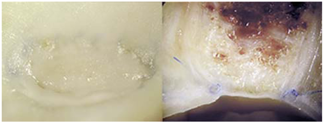
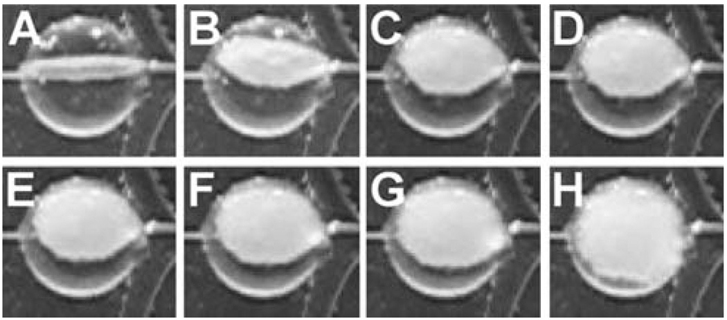
SMP foams based on DiAPLEX polyurethane have been investigated as a material to occlude aneurysms. Metcalfe et al.55 performed a series of experiments in which the so-called CHEM (Cold Hibernated Elastic Memory) foams were surgically inserted into dog model aneurysms. The results of the study demonstrated that the open cellular structure of the SMP foam favored an in-growth of the cells involved in neointima formation (Fig. 4). Recent in vitro cytocompatibility tests of the CHEM foams also suggested healing would proceed effectively in vivo.57 Maitland et al. developed an endovascular treatment technique to deliver thermally deployed SMP foams based on polyurethanes synthesized in-house.71 A foam spheroid was compressed over a light diffusing fiber coupled to a diode laser (810 nm) and delivered into the aneurysm sac in an in vitro model, where it was photothermally expanded (Fig. 5). Based on computer simulations by Ortega et al.,72,73 filling the aneurysm (using standard GDCs or SMP foam) may result in increased wall shear stress in the parent artery, potentially leading to endothelial cell damage. The ability to machine specific foam shapes may enable the reduction of such shear stresses by selectively modifying the post-treatment artery lumen shape.
Fig. 4.
Macroscopic photographs of a dog lateral wall common carotid aneurysm embolized with CHEM foam. (Left) “En face” view of the aneurysm neck and (right) axial section image show complete aneurysm occlusion with good neointimal formation across the neck. (Reprinted with permission from A. Metcalfe, A. Desfaits, I. Salazkin, L. Yahia, W. M. Sokolowski and J. Raymond, Cold hibernated elastic memory foams for endovascular interventions, Biomaterials, 2003, 24, 491.55)
Fig. 5.
Temporal sequence of photothermal expansion of SMP foam in an in vitro aneurysm model. The aneurysm sac is located at the bifurcation of the main vessel. (Reprinted with permission from D. J. Maitland, W. Small, IV, J. M. Ortega, P. R. Buckley, J. Rodriguez, J. Hartman, and T. S. Wilson, Prototype laser-activated shape memory polymer foam device for embolic treatment of aneurysms, J. Biomed. Opt., 2007, 12, 030504.71)
Wide-necked aneurysms are more difficult to treat, requiring staged treatment methods such as stent-assisted coil embolization or balloon remodeling74,75 in which a stent or balloon is used to prevent migration of the embolic coils into the parent artery. The stent-assisted technique involves endovascular placement of a stent in the parent artery across the aneurysm neck followed by delivery of embolic coils through the stent interstices into the aneurysm lumen. The balloon remodeling technique consists of temporary inflation of a balloon at the end of a microcatheter in the parent artery across the aneurysm neck during embolic coil delivery; since only one coil can be delivered at a time, the balloon is periodically deflated for delivery of successive coils and then removed once the final coil is delivered. Though these endovascular methods have demonstrated success in wide-necked aneurysms, they are not always viable for fusiform aneurysms which have no identifiable neck. In such cases, treatment options are generally limited to open surgical techniques including occlusion of the parent artery, bypass, or clipping of the aneurysm.75
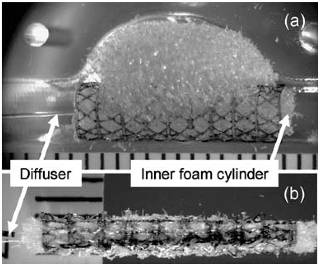
Small et al.37 developed a prototype device for endovascular embolization of fusiform (non-necked) aneurysms based on thermally activated SMP. The device consisted of two main components: (1) an SMP stent and (2) an SMP embolic foam attached to the outside of the stent. The device was compressed over a light diffusing fiber for photothermal actuation. The embolic foam component filled the aneurysm lumen while the stent maintained a patent flow channel in the parent artery in an in vitro model (Fig. 6).
Fig. 6.
SMP stent-foam device with removable inner foam cylinder and laser light diffuser (a) before and (b) after collapsing for delivery. The device is shown in the bottom mold of the fusiform aneurysm model in (a). Scale divisions are in millimetres. (Reprinted with permission from W. Small, IV, P. R. Buckley, T. S. Wilson, W. J. Benett, J. Hartman, D. Saloner and D. J. Maitland, Shape memory polymer stent with expandable foam: a new concept for endovascular embolization of fusiform aneurysms, IEEE Trans. Biomed. Eng., 2007, 54, 1157.37)
5.1.3 Vascular stents
Vascular stents are small tubular scaffolds used to maintain the patency of an artery. They are widely used in conjunction with transluminal angioplasty in the treatment of arterial stenosis (narrowing of the vessel) to prevent acute vessel closure and late restenosis in a variety of large vessels such as coronary arteries,76 carotid arteries,77 and iliac arteries.78 Most stents are currently made of stainless steel, SMAs, and other metal alloys. Crimped over a catheter, they are navigated to the lesion site where they are expanded either by balloon expansion or by self-expansion. Though improvements in design and coating with drug-eluting agents have resulted in smaller, safer, and more biocompatible stents with reduced rates of restenosis,79 several drawbacks associated with the use of metallic stents still exist. First, metallic stents are too stiff to navigate highly tortuous vessels such as those of the neurovasculature; the need for treatment of stroke and intracranial stenosis is well known,80 but successful stenting with the current technology has been shown in a limited number of cases only.81 Second, compliance mismatch due to the stiffness of metallic stents at the arterial wall may potentially be a contributing factor in restenosis.82 Third, drug elution is currently achieved by coating the metal with a drug-doped polymer, which requires a costly additional fabrication step.83 The increased flexibility, compliance, and relatively simple drug-embedding capability of SMPs could overcome the problems encountered with current metallic vascular stents.
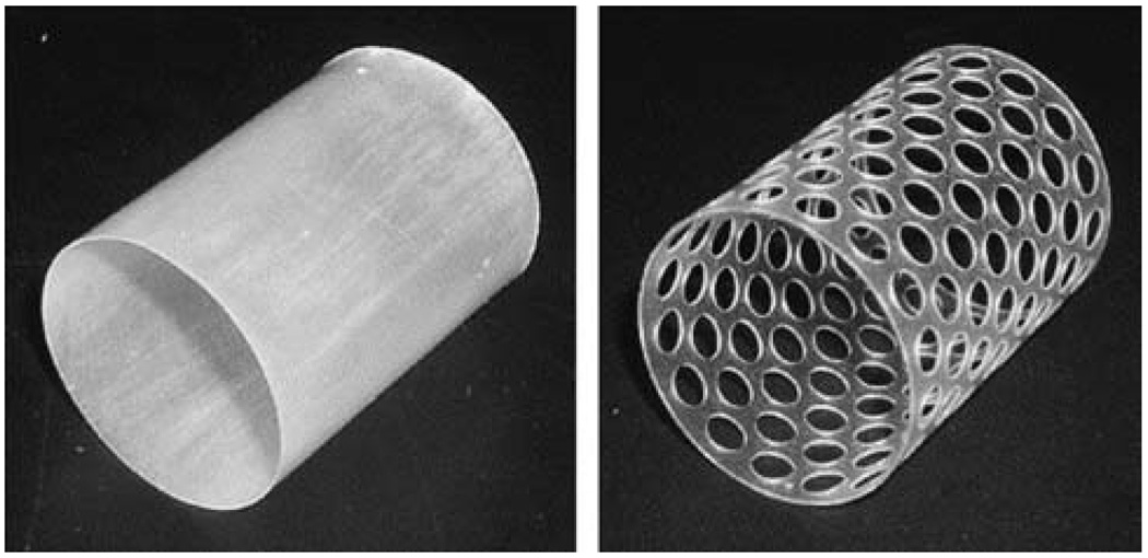
Wache et al.84 introduced the concept of a drug-eluting SMP stent. Barium sulfate was added to the tubular thermoplastic polyurethane stent for radio-opacity, and the drug was loaded during normal injection molding and dip coating processing steps. In vitro testing showed steady drug release over a 1 week period. Gall et al.85 and Yakacki et al.86 described thermally responsive acrylate-based SMP stent prototypes fabricated by drilling holes in an injection molded tube (Fig. 7), and demonstrated shape recovery at body temperature (37 °C). A photothermally actuated prototype stent fabricated from DiAPLEX SMP was reported by Baer et al.87 A SMP tube, created by dip coating a stainless steel rod, was laser-etched to create a strut pattern based on an imported computer-aided design (CAD) file. The stent was compressed over a light diffusing fiber and light from a diode laser at a wavelength of 810 nm was used to photothermally expand the stent in water flow. The group investigated the collapse pressure of similar laser-etched SMP stents as well as solid tubular stents, noting that the solid tubular stent withstood the maximum pressure expected to be exerted by an artery while the laser-etched stent in its current form may be susceptible to collapse at higher than normal body temperature (e.g., high grade fever).88 A biodegradable SMP prototype stent was proposed by Ajili et al.89 The material showed good adhesion and proliferation of mesenchymal stem cells in vitro, suggesting a potential coating to enhance healing after implantation.
Fig. 7.
Design of solid and 50% perforated SMP stents. (Reprinted with permission from C. M. Yakacki, R. Shandas, C. Lanning, B. Rech, A. Eckstein and K. Gall, Unconstrained recovery characterization of shape-memory polymer networks for cardiovascular applications, Biomaterials, 2007, 28, 2255.86)
5.2 Cardiac valve repair
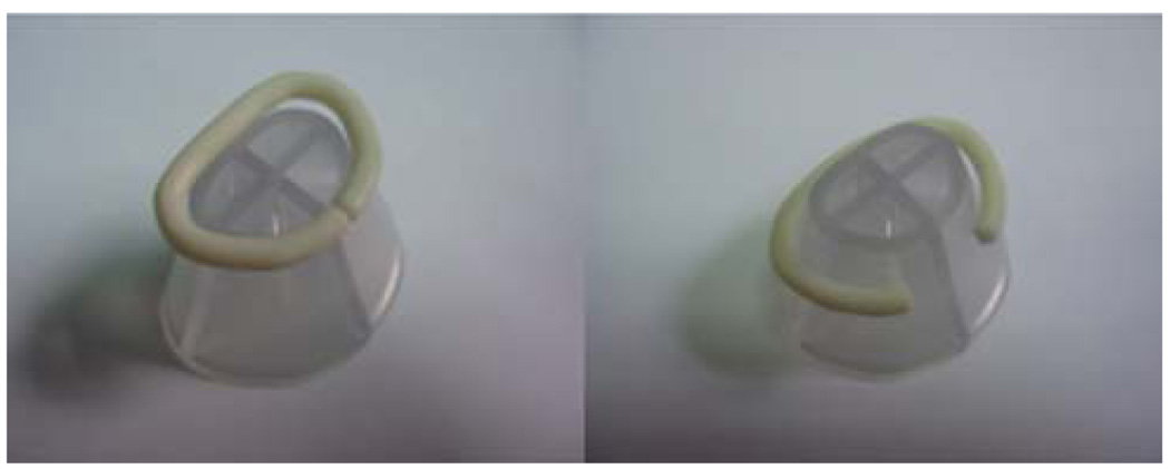
Mitral valve insufficiency occurs when the mitral valve does not close properly, resulting in the regurgitation of blood from the left ventricle to the left atrium (flow reversal). Valve repair (e.g., ring annuloplasty), as opposed to replacement, is the preferred method of treatment.90 The current ring annuloplasty procedure consists of implanting a prosthetic ring to immediately reduce the orifice diameter and improve contact between the valve leaflets. Lantada et al.91 proposed a resistively heated SMP ring to enhance the annuloplasty procedure for remotely controlled post-operative diameter reduction (Fig. 8). The thermally responsive SMP ring would be implanted in a temporary shape corresponding to the shape of the patient’s malfunctioning mitral valve, reducing the acute impact of the procedure on the heart. The SMP ring diameter would be reduced gradually post-operatively by applying a current to the embedded resistive elements while monitoring the valve operation. Alternatively, inductive heating could potentially be used for actuation by embedding magnetic particles in the SMP ring.48,51
Fig. 8.
SMP annuloplasty ring shown in its (left) primary and (right) temporary forms. The ring is shown on the base used to set the temporary shape. (Reprinted with permission from A. D. Lantada, P. LaFont, I. Rada, A. Jimenez, J. L. Hernandez, H. Lorenzo-Yustos, and J. Munoz-Garcia, Active Annuloplasty System for Mitral Valve Insufficiency, in BIOSTEC 2008, CCIS 25, ed. A. Fred, J. Filipe and H. Gamboa, Springer-Verlag, Berlin, 2008, pp. 59–72.91)
5.3 Tissue engineering
The advent of biodegradable SMPs12,92–106 spurred the investigation of their use as a vehicle for minimally invasive tissue engineering. In theory, tissues can be grown on collapsible SMP scaffolds in vitro and potentially delivered into the body using minimally invasive techniques (e.g., catheter) and implanted to initiate repair or reconstruction of tissues or organs. The previously described implantable SMP embolic devices and stents represent potential endovascular tissue engineering applications, as both types of device result in the eventual in-growth of cells around the SMP structure as part of the healing process. Other potential minimally invasive tissue engineering scenarios in which biodegradable SMP scaffolds could be applied include pharyngeal mucosa reconstruction, bone regeneration, and organ repair.
Researchers have reported the use of thermally responsive SMPs as an extracellular matrix for growing various tissues in vitro. Rickert et al.107 reported cell seeding on a biodegradable thermoplastic SMP based on poly(ε-caprolactone). To investigate the possibility of reconstructing the mucosa of the upper aerodigestive tract, rat pharyngeal cells were seeded on smooth and porous surfaces of the SMP with encouraging results. Neuss et al.17 analyzed the cell behavior of L929 mouse fibroblasts, human mesenchymal stem cells, human mesothelial cells, and rat mesothelial cells on a similar poly(ε-caprolactone) SMP network. Mesothelial cells form an anti-adhesive surface layer in vivo108 that may support abdominal repair or regeneration. Mesenchymal stem cells, the precursor cells of bone, fat, cartilage, and muscle,109 may support bone regeneration or the production of adipose tissue. Cell proliferation of all cell types and the differentiation capacity of mesenchymal stem cells were supported by the SMP. Furthermore, thermal activation of the shape memory effect did not affect the majority of adherent cells.
5.4 Other specialized fields
5.4.1 Orthopedics
The anterior cruciate ligament (ACL) is one of the primary stabilizing ligaments in the knee. A partial or complete tear of this ligament, very commonly seen in athletes, is a serious injury leading to destabilization of the knee. Methyl methacrylate (MMA) and poly(ethylene glycol)n dimethacrylate (PEGDMA) copolymers have been studied by Yakacki et al. for a possible high strength shape memory biomaterial.59 These materials demonstrate a rubbery modulus in the range of 9.3 to 23.0 MPa. A SMP ShapeLoc™ fixation device for soft tissue fixation in ACL tear has been proposed (Fig. 9).59
Fig. 9.
Demonstration of shape memory polymer cylindrical device expanding for soft tissue fixation. Note: black lines were drawn for visualization. (Reprinted with permission from C. M. Yakacki, R. Shandas, D. Safranski, A. M. Ortega, K. Sassaman and K. Gall, Strong, tailored, biocompatible shape-memory polymer networks, Adv. Funct. Mater., 2008, 18, 2428.59)
5.4.2 Endoscopic surgery
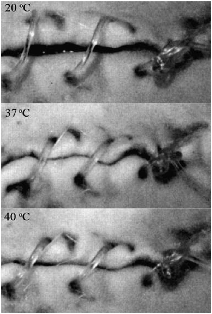
Achieving proper closure of an incision or open lumen using endoscopic instruments can present a challenge. Lendlein and Langer12 demonstrated the concept of biodegradable thermally responsive SMP sutures. An extruded monofilament of oligo(ε-caprolactone)diol-based SMP was stretched under heat and cooled to stabilize the temporary form. An abdominal wound in a rat was loosely sutured using the SMP fiber, and then heated to body temperature to achieve wound closure (Fig. 10).
Fig. 10.
Biodegradable SMP suture for wound closure. The photoseries from the animal experiment shows the shrinkage of the suture as temperature increases. (Reprinted with permission from A. Lendlein and R. Langer, Biodegradable, elastic shape-memory polymers for potential biomedical applications, Science, 2002, 296, 1673.12)
5.4.3 Orthodontics
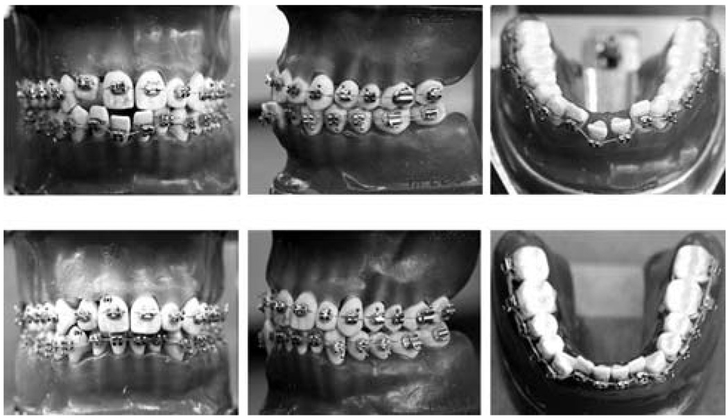
SMPs may provide an alternative to traditional materials used for the treatment of dental malocclusions. Nakasima et al.110 introduced the concept of using a thermally responsive SMP arch wire in orthodontic braces for aligning teeth, noting that the recovery force was feasible for moving teeth and that the SMP was more aesthetically appealing than a traditional metallic arch wire. These features were echoed in a more recent study by Jung et al.,111 in which an extruded SMP wire, in a stretched state at room temperature, was attached to stainless steel brackets bonded to teeth in a dental model. When heated, the teeth slowly moved into alignment (Fig. 11). Thermomechanical testing showed that the SMP wire maintained a steady shape recovery force for over 3 months.
Fig. 11.
Photographs of the orthodontic appliance (top) before and (bottom) after treatment. The movement of the misaligned teeth due to a lateral force originating from the shape recovery of the SMP arch wire is seen. (Reprinted with permission from Y. C. Jung and J. W. Cho, J. Mater. Sci. Mater. Med., 2008, 1–6.111)
5.4.4 Kidney dialysis
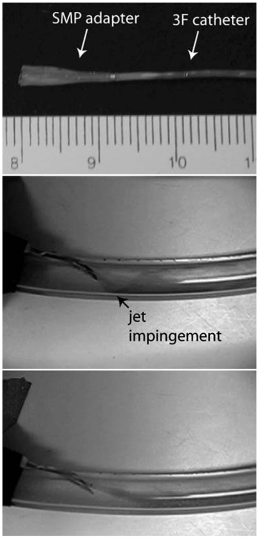
Vascular access complications occur in kidney dialysis patients as a result of arteriovenous (AV) graft flow decline caused by the development of stenotic lesions.112 Vascular damage caused by excessive wall shear stress may contribute to lesion formation.113,114 Ortega et al.115 investigated the use of a SMP adapter for a kidney dialysis needle to reduce the hemodynamic stress on the AV graft wall by tailoring the flow out of the needle. Computational fluid dynamics simulations demonstrated that the adapter significantly reduces the graft wall shear stress, which could potentially reduce vascular access occlusion. A prototype SMP adapter was positioned inside a dialysis needle in a compact form and thermally expanded by heated water flow in an in vitro AV graft model. Flow visualization experiments showed the adapter redirected the needle flow such that it is more aligned with the background graft flow (Fig. 12).
Fig. 12.
(Top) SMP adapter (in primary expanded form) mounted on a catheter for insertion into the dialysis needle (scale divisions in millimetres). Flow visualization within the AV graft model (middle) without and (bottom) with the SMP adapter. Jet impingement from the needle on the graft wall (black arrow) is evident when the adapter is not used. (Reprinted with permission from J. M. Ortega, W. Small, IV, T. S. Wilson, W. J. Benett, J. M. Loge and D. J. Maitland, A shape memory polymer dialysis needle adapter for the reduction of hemodynamic stress within arteriovenous grafts, IEEE Trans. Biomed. Eng., 2007, 54, 1722–1724.115)
5.4.5 Neuroprosthetics
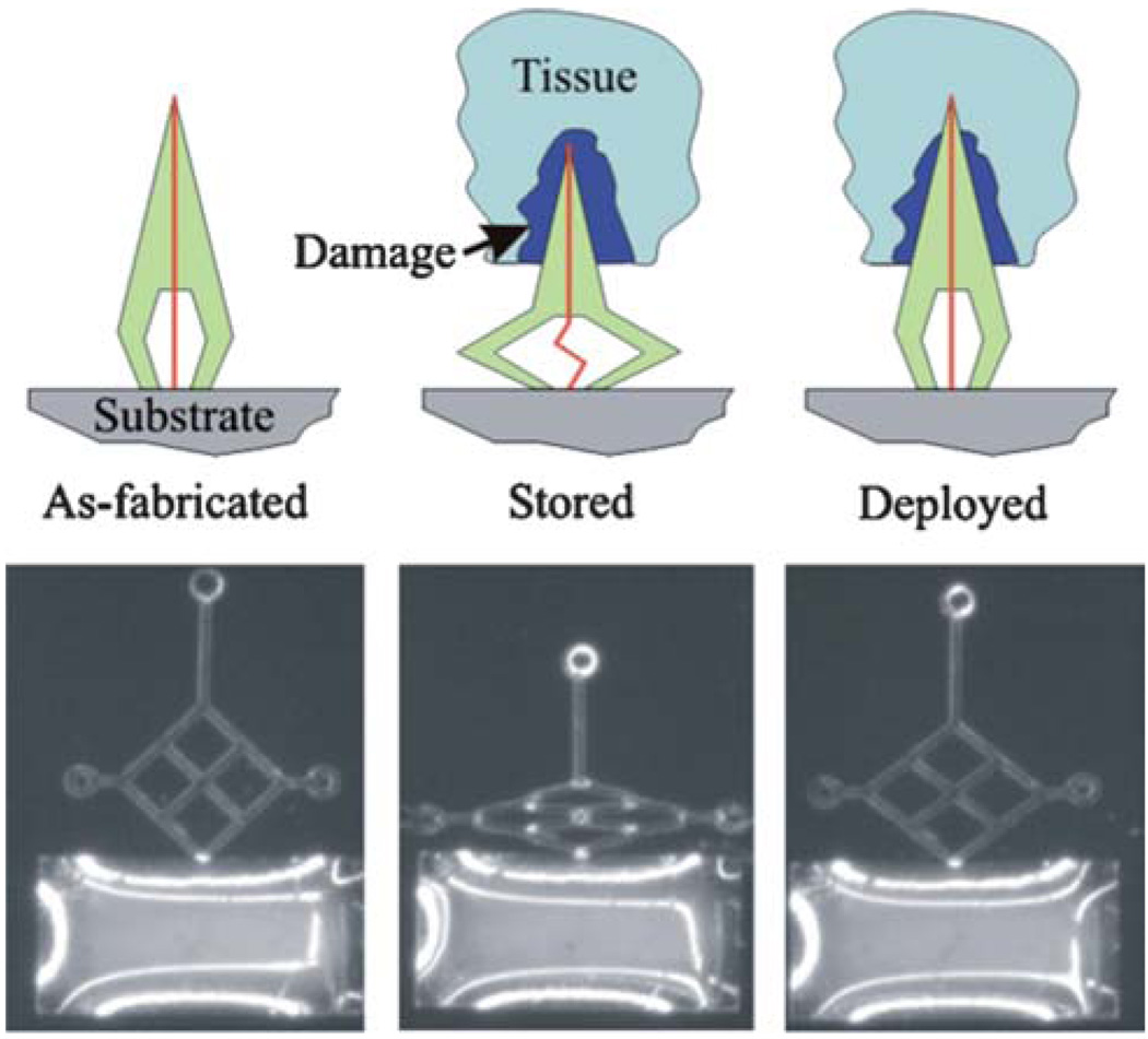
Neuronal probes used to monitor and stimulate brain activity are susceptible to failure due to the tissue damage induced during the initial insertion procedure.116 To reduce the extent of damage, Sharp et al.117 reported a prototype neuronal probe using a body temperature-activated SMP microactuator for slow insertion into the brain tissue (Fig. 13). Results in mice showed that slow insertion (1 mm per 40 min) reduced the amount of tissue damage.
Fig. 13.
(Top) Schematic representation of the SMP neuronal probe actuator. The probe is fabricated with an enclosed conductor (vertical line) and deformed into a “crouched” conformation. It is then inserted surgically into the brain, resulting in an inflammatory response around the probe (damage). The heat from the body then causes slow actuation of the SMP probe back to its original conformation and moves the probe tip beyond the zone of tissue damage created by implantation. (Bottom) Light micrograph of a prototype SMP probe. The first panel shows a light micrograph of the as-fabricated prototype SMP probe. The middle panel shows the deformed or “crouched” configuration of the probe after it was stretched horizontally. The final panel shows the recovered conformation after deployment at 37 °C. (Reprinted with permission from A.A. Sharp,H.V. Panchawagh, A. Ortega, R. Artale, S. Richardson-Burns, D. S. Finch, K. Gall, R. L. Mahajan and D. Restrepo, Toward a self-deploying shape memory polymer neuronal electrode, J. Neural Eng., 2006, 3, 23–30.117)
5.4.6 Light-based therapy
Endoluminal and interstitial light-based therapies such as thermal laser therapies118,119 and photodynamic therapy120–124 require the use of a light-emitting device capable of being delivered through a needle, catheter, or endoscope. Small et al.125 reported a technique for constructing high power light diffusing devices comprised of a flexible SMP cylindrical diffuser attached to the tip of an optical fiber. This device was also used for photothermal actuation of the group’s SMP embolic foam and stent devices mentioned previously.37,71,87 The ability to tailor the SMP stiffness for a particular application is a novel capability relative to commercially available light diffusers.
5.4.7 Bio-MEMs
Shape memory polymer based Micro-Electro Mechanical (MEM) systems have been proposed by several investigators126–130 for rapid and accurate blind placement and release of medical devices in the body. Also, micropumps for drug delivery have been designed from shape memory alloys for fine control of fluids at the rate of 1–10 µl min−1.131–134 These devices hold a lot of untapped potential due to the relatively low stiffness of SMPs. This issue has triggered efforts to develop composite SMPs135–140 that can provide the biocompatibility of polymers as well as the stiffness/conductivity of metals. Liu et al. and Ratna et al. provide a comprehensive review of efforts in this direction.5,9
6. Conclusion
Many groups worldwide, industrial and academic, are pursuing medical applications of SMP. The commercial availability of SMPs, independent of the application, is in a constant state of flux. A non-comprehensive list of currently available SMPs includes those from DiAPLEX (thermoplastic and thermoset polyurethane), Cornerstone Research Group (Veriflex®, Verilyte™, Veritex™: thermoset polystyrene), Lubrizol Advanced Materials (Tecoflex®: aliphatic thermoplastic urethane), and Composite Technology Development, Inc. (TEMBO®: thermoset epoxy). The application of SMPs in medicine is, however, limited due to the lack of a commercial supplier of medical-grade materials. As more small companies drive worldwide regulatory agencies to approve specific devices and material chemistries, the attraction of profit is likely to initiate the commercial availability of medical-grade SMPs. In the interim, academic and small business communities will likely drive the medical application of SMPs.
The SMPs that have been published to date have sufficient thermomechanical and shape memory properties to succeed as medical devices. The first US Food and Drug Administration approval of a medical SMP device was granted in 2008 for an orthopedic anchor (Medshape Solutions, Inc., www.med-shapesolutions.com). The primary hurdles for the early applications of SMPs in medicine will be limited to business (e.g. regulatory, intellectual property, manufacturing) and engineering challenges. Even in the short term, however, poor biocompatibility could have long-term negative consequences on the adoption of SMP as a biomedical material.
In the mid-to-long-term, there are a number of potential areas for innovation in medical SMPs. As examples, we note the need for improved stress recovery, better manufacturability, and remotely modified chemistry. Given that SMPs have superior strain recovery in comparison to shape memory alloys (SMAs), the first area of improvement is increase stress recovery. A reduction in strain recovery for increased stress recovery is desirable in a number of applications. For example, our work in developing an embolectomy device led to a hybrid SMP–SMA design that was necessitated by the force required to actuate the device.62 A second area for material chemistry improvements would be to design chemical structures that can more easily and cheaply be manufactured. A thermoplastic SMP that could be easily molded and machined and then subsequently treated (e.g. heat, radiation, chemical) to lock (e.g. crosslink) that form into the primary shape would be desirable. A third development that would open up new application areas would be a material that could be remotely triggered to change from a biostable to a biodegradable chemical structure. Examples of devices that have terminal utility are endovascular protective filters. These, traditionally, metal devices are placed in vessels like the inferior vena cava to prevent blood clots from traveling from the lower body into the lungs. In many cases these devices are only needed for months but are placed permanently. If, once the clinical threat of clots is reduced, these filters could be triggered to become biodegradable then the negative side effects of a permanent device could be avoided.
Acknowledgements
This work was supported by the National Institutes of Health, National Institute of Biomedical Imaging and Bioengineering Grant R01EB000462 and partially performed under the auspices of the US Department of Energy by Lawrence Livermore National Laboratory under Contract DE-AC52-07NA27344.
Biographies

Ward Small IV
Ward Small IV received the BS degree in engineering physics from the University of California, San Diego, in 1993 and the PhD degree in engineering/applied science from the University of California, Davis, in 1998. From 1998 to 2003, he investigated the use of light-activated photodynamic therapy drugs at Miravant Medical Technologies. He joined Lawrence Livermore National Laboratory in 2003 where he develops polymer-based actuators for therapeutic medical devices. He has authored 25 peer-reviewed journal articles and over 30 conference proceedings articles and abstracts. His research interests include biomedical optics and endovascular device development.

Pooja Singhal
Pooja Singhal obtained her B. Tech in Chemical Engineering from Indian Institute of Technology, Kanpur in 2005. After working in industry, she entered a PhD track program in Biomedical Engineering at Texas A&M University in 2008. Her research is focused on developing biocompatible shape memory polymers for implantable medical devices.

Thomas S. Wilson
Thomas S. Wilson received the BS degree from the University of Wisconsin, Madison, in 1985 and the PhD degree from Virginia Polytechnic Institute and State University, Blacksburg, in 1991, both in chemical engineering. From 1991 to 2000, he was with Rohm and Hass Company, where he characterized rheological, thermal, and physical properties of polymeric materials with application to new material development and material processing. Since 2000, he has worked at Lawrence Livermore National Laboratory. His current research interests include synthesis and characterization of new shape memory polymers, hydrogels, and biomaterials for medical devices, biosensors, and artificial organs.

Duncan Maitland
Duncan Maitland has worked as an engineer in aerospace, national defense and biomedical applications since 1985. As of January 2008 he joined the Department of Biomedical Engineering at Texas A&M University as an Associate Professor. In 1995 he received his PhD in Biomedical Engineering from Northwestern University where he studied tissue denaturation kinetics. Dr Maitland has 40 archival publications and 11 granted patents, has commercialized three medical devices, serves on several NIH study sections, and has received peer-reviewed funding from NIH, DOE and NSF. His research interests include endovascular interventional devices and basic device-body interactions including computational and experimental techniques.
Footnotes
This paper is part of a Journal of Materials Chemistry themed issue on Actively Moving Polymers. Guest editor: Andreas Lendlein.
References
- 1.El Feninant F, Laroche G, Fiset M, Mantovani D. Adv. Eng. Mater. 2002;4:91–104. [Google Scholar]
- 2.Chaterji S, Kwon IK, Park K. Prog. Polym. Sci. 2007;32:1083–1122. doi: 10.1016/j.progpolymsci.2007.05.018. [DOI] [PMC free article] [PubMed] [Google Scholar]
- 3.Sokolowski W, Metcalfe A, Hayashi S, Yahia L, Raymond J. Biomed. Mater. (Bristol, U. K.) 2007;2:S23–S27. doi: 10.1088/1748-6041/2/1/S04. [DOI] [PubMed] [Google Scholar]
- 4.Lendlein A, Kelch S. Angew. Chem., Int. Ed. 2002;41:2034–2057. [PubMed] [Google Scholar]
- 5.Liu C, Qin H, Mather PT. J. Mater. Chem. 2007;17:1543–1558. [Google Scholar]
- 6.Dietsch B, Tong T. J. Adv. Mater. 2007;39:3–12. [Google Scholar]
- 7.Gunes IS, Jana SC. J. Nanosci. Nanotechnol. 2008;8:1616–1637. [PubMed] [Google Scholar]
- 8.Mano JF. Adv. Eng. Mater. 2008;10:515–527. [Google Scholar]
- 9.Ratna D, Karger-Kocsis J. J. Mater. Sci. 2008;43:254–269. [Google Scholar]
- 10.Rousseau IA. Polym. Eng. Sci. 2008;48:2075–2089. [Google Scholar]
- 11.Mather PT, Luo X, Rousseau IA. Annu. Rev. Mater. Res. 2009;39:445–471. [Google Scholar]
- 12.Lendlein A, Langer R. Science. 2002;296:1673–1676. doi: 10.1126/science.1066102. [DOI] [PubMed] [Google Scholar]
- 13.Fare S, Valtulina V, Petrini P, Alessandrini E, Pietrocola G, Tanzi MC, Speziale P, Visai L. J. Biomed. Mater. Res., Part A. 2005;73:1–11. doi: 10.1002/jbm.a.30193. [DOI] [PubMed] [Google Scholar]
- 14.Cabanlit M, Maitland DJ, Wilson TS, Simon S, Wun T, Gershwin ME, Van de water J. Macromol. Biosci. 2007;7:48–55. doi: 10.1002/mabi.200600177. [DOI] [PubMed] [Google Scholar]
- 15.Ping P, Wang W, Zhang P, Chen X, Jing X. Front. Chem. China. 2007;2:331–336. [Google Scholar]
- 16.Yakacki CM, Lyons MB, Rech B, Gall K, Shandas R. Biomed. Mater. (Bristol, U. K.) 2008;3:15010–15019. doi: 10.1088/1748-6041/3/1/015010. [DOI] [PubMed] [Google Scholar]
- 17.Neuss S, Blomenkamp I, Stainforth R, Boltersdorf D, Jansen M, Butz N, Perez-Bouza A, Knuchel R. Biomaterials. 2009;30:1697–1705. doi: 10.1016/j.biomaterials.2008.12.027. [DOI] [PubMed] [Google Scholar]
- 18.Lendlein A, Zotzmann J, Feng Y, Alteheld A, Kelch S. Biomacromolecules. 2009;10:975–982. doi: 10.1021/bm900038e. [DOI] [PubMed] [Google Scholar]
- 19.Wilson TS, Bearinger JP, Herberg JL, Marion JE, III, Wright WJ, Evans CL, Maitland DJ. J. Appl. Polym. Sci. 2007;106:540–551. [Google Scholar]
- 20.Hiltz JA. Shape Memory Polymers: Literature Review. Ottawa, Ontario, Canada, TM: Defence R&D Canada; 2002. 2002-127. [Google Scholar]
- 21.Flory PJ. Principles of Polymer Chemistry. Ithaca: Cornell University Press; 1969. [Google Scholar]
- 22.Tobushi H, Shimada D, Hayashi S, Endo M. Proc. Inst. Mech. Eng., Part L. 2003;217:135–143. [Google Scholar]
- 23.Jeon HG, Mather PT, Haddad TS. Polym. Int. 2000;49:453–457. [Google Scholar]
- 24.Osada Y, Gong JP. Adv. Mater. 1998;10:827–837. [Google Scholar]
- 25.Osada Y, Matsuda A. Nature. 1995;376:219. doi: 10.1038/376219a0. [DOI] [PubMed] [Google Scholar]
- 26.Li F, Zhu W, Zhang X, Zhao C, Xu M. J. Appl. Polym. Sci. 1998;71:1063–1070. [Google Scholar]
- 27.Jeong HM, Song JH, Chi KW, Kim I, Kim KT. Polym. Int. 2002;51:275–280. [Google Scholar]
- 28.Chen W, Zhu C, Gu X. J. Appl. Polym. Sci. 2002;84:1504–1512. [Google Scholar]
- 29.Li F, Larock RC. J. Appl. Polym. Sci. 2002;84:1533–1543. [Google Scholar]
- 30.Bellin I, Kelch S, Langer R, Lendlein A. Proc. Natl. Acad. Sci. U. S. A. 2006;103:18043–18047. doi: 10.1073/pnas.0608586103. [DOI] [PMC free article] [PubMed] [Google Scholar]
- 31.Monkman GJ. Mechatronics. 2000;10:489–498. [Google Scholar]
- 32.Tobushi H, Hara H, Yamada E, Hayashi S. Smart Mater. Struct. 1996;5:483–491. [Google Scholar]
- 33.Tobushi H, Hashimoto T, Ito N, Hayashi S, Yamada E. J. Intell. Mater. Syst. Struct. 1998;9:127. [Google Scholar]
- 34.Tobushi H, Hayashi S, Kojima S. JSME Int. J., Ser. I. 1992;35:296–302. [Google Scholar]
- 35.Domeier L, Nissen A, Goods S, Whinnery LR, McElhanon J. J. Appl. Polym. Sci. 2010;115:3217–3229. [Google Scholar]
- 36.Liu C, Mather PT. J. Appl. Med. Polym. 2002;6:47–52. [Google Scholar]
- 37.Small W, IV, Buckley PR, Wilson TS, Benett WJ, Hartman J, Saloner D, Maitland DJ. IEEE Trans. Biomed. Eng. 2007;54:1157–1160. doi: 10.1109/TBME.2006.889771. [DOI] [PubMed] [Google Scholar]
- 38.Small W, IV, Metzger MF, Wilson TS, Maitland DJ. IEEE J. Sel. Top. Quantum Electron. 2005;11:892–901. [Google Scholar]
- 39.Small W, IV, Wilson TS, Benett WJ, Loge JM, Maitland DJ. Opt. Express. 2005;13:8204–8213. doi: 10.1364/opex.13.008204. [DOI] [PubMed] [Google Scholar]
- 40.Sahoo NG, Jung YC, Cho JW. Mater. Manuf. Processes. 2007;22:419–423. [Google Scholar]
- 41.Sahoo NG, Jung YC, Goo NS, Cho JW. Macromol. Mater. Eng. 2005;290:1049–1055. [Google Scholar]
- 42.Leng JS, Lv HB, Liu YJ, Du SY. Appl. Phys. Lett. 2007;91 144105. [Google Scholar]
- 43.Leng JS, Lan X, Liu YJ, Du SY, Huang WM, Liu N, Phee SJ, Yuan Q. Appl. Phys. Lett. 2008;92 014104. [Google Scholar]
- 44.Qi HJ, Nguyen TD, Castroa F, Yakacki CM, Shandas R. J. Mech. Phys. Solids. 2008;56:1730–1751. [Google Scholar]
- 45.Khonakdar HA, Jafari SH, Rasouli S, Morshedian J, Abedini H. Macromol. Theory Simul. 2007;16:43–52. [Google Scholar]
- 46.Yang B, Huang WM, Li C, Li L. Polymer. 2006;47:1348–1356. [Google Scholar]
- 47.Hazelton CS, Arzberger SC, Lake MS, Munshi NA. J. Adv. Mater. 2007;39:35–39. [Google Scholar]
- 48.Mohr R, Kratz K, Weigel T, Lucka-Gabor M, Moneke M, Lendlein A. Proc. Natl. Acad. Sci. U. S. A. 2006;103:3540–3545. doi: 10.1073/pnas.0600079103. [DOI] [PMC free article] [PubMed] [Google Scholar]
- 49.Schmidt AM. Macromol. Rapid Commun. 2006;27:1168–1172. [Google Scholar]
- 50.Razzaq MY, Anhalt M, Frormann L, Weidenfeller B. Mater. Sci. Eng., A. 2007;444:227–235. [Google Scholar]
- 51.Buckley PR, McKinley GH, Wilson TS, Small W, IV, Benett WJ, Bearinger JP, McElfresh MW, Maitland DJ. IEEE Trans. Biomed. Eng. 2006;53:2075–2083. doi: 10.1109/TBME.2006.877113. [DOI] [PubMed] [Google Scholar]
- 52.Jung YC, So HH, Cho JW. J. Macromol. Sci., Part B: Phys. 2006;45:453–461. J. Macromol. Sci., Part B: Phys., 2006, 445, 1189, Erratum. [Google Scholar]
- 53.Lv HB, Leng JS, Liu YJ, Du SY. Adv. Eng. Mater. 2008;10:592–595. [Google Scholar]
- 54.Chen MC, Tsai HW, Chang Y, Lai WY, Mi FL, Liu CT, Wong HS, Sung HW. Biomacromolecules. 2007;8:2774–2780. doi: 10.1021/bm7004615. [DOI] [PubMed] [Google Scholar]
- 55.Metcalfe A, Desfaits A, Salazkin I, Yahia L, Sokolowski WM, Raymond J. Biomaterials. 2003;24:491–497. doi: 10.1016/s0142-9612(02)00362-9. [DOI] [PubMed] [Google Scholar]
- 56.Ratner BD, Hoffman AS, Schoen FJ, Lemons JE. Biomaterials Science: An Introduction to Materials in Medicine. San Diego, CA, USA: Academic press; 2004. [Google Scholar]
- 57.De Nardo L, Alberti R, Cigada A, Yahia L, Tanzi MC, Fare S. Acta Biomater. 2009;5:1508–1518. doi: 10.1016/j.actbio.2008.11.017. [DOI] [PubMed] [Google Scholar]
- 58.Lamba NMK, Woodhouse KA, Cooper SL, Lelah MD. Polyurethanes in Biomedical Applications. Boca Raton, FL, USA: CRC Press; 1997. [Google Scholar]
- 59.Yakacki CM, Shandas R, Safranski D, Ortega AM, Sassaman K, Gall K. Adv. Funct. Mater. 2008;18:2428–2435. doi: 10.1002/adfm.200701049. [DOI] [PMC free article] [PubMed] [Google Scholar]
- 60.Maitland DJ, Metzger MF, Schumann D, Lee A, Wilson TS. Lasers Surg. Med. 2002;30:1–11. doi: 10.1002/lsm.10007. [DOI] [PubMed] [Google Scholar]
- 61.Metzger MF, Wilson TS, Schumann D, Matthews DL, Maitland DJ. Biomed. Microdevices. 2002;4:89–96. [Google Scholar]
- 62.Small W, IV, Wilson TS, Buckley PR, Benett WJ, Loge JM, Hartman J, Maitland DJ. IEEE Trans. Biomed. Eng. 2007;54:1657–1666. doi: 10.1109/TBME.2007.892921. [DOI] [PubMed] [Google Scholar]
- 63.Hartman J, Small W, IV, Wilson TS, Brock J, Buckley PR, Benett WJ, Loge JM, Maitland DJ. Am. J. Neuroradiol. 2007;28:872–874. [PMC free article] [PubMed] [Google Scholar]
- 64.Henkes H, Fischer S, Liebig T, Weber W, Reinartz J, Miloslavski E, Kuhne D. Neurosurgery. 2006;58:224–232. doi: 10.1227/01.NEU.0000194831.54183.3F. [DOI] [PubMed] [Google Scholar]
- 65.Gallas S, Pasco A, Cottier J, Gabrillargues J, Drouineau J, Cognard C, Herbreteau D. Am. J. Neuroradiol. 2005;26:1723–1731. [PMC free article] [PubMed] [Google Scholar]
- 66.Fernandez Zubillaga A, Gugliemi G, Vinuela F, Duckwiler GR. AJNR Am. J. Neuroradiol. 1994;15:815–820. [PMC free article] [PubMed] [Google Scholar]
- 67.Redekop G, Willinski R, Montanera W, TerBrugge K, Tymianski M, Wallace MC. Can. J. Neurol. Sci. 1999;26:172–181. doi: 10.1017/s0317167100000214. [DOI] [PubMed] [Google Scholar]
- 68.Murayama Y, Tateshima S, Gonzales NR, Vinuela F. Stroke. 2003;34:2031–2037. doi: 10.1161/01.STR.0000083394.33633.C2. [DOI] [PubMed] [Google Scholar]
- 69.Niimi Y, Song J, Madrid M, Berenstein A. Stroke. 2006;37:1028–1032. doi: 10.1161/01.STR.0000206459.73897.a3. [DOI] [PubMed] [Google Scholar]
- 70.Hampikian JM, Heaton BC, Tong FC, Zhang Z, Wong CP. Mater. Sci. Eng., C. 2006;26:1373–1379. [Google Scholar]
- 71.Maitland DJ, Small W, IV, Ortega JM, Buckley PR, Rodriguez J, Hartman J, Wilson TS. J. Biomed. Opt. 2007;12 doi: 10.1117/1.2743983. 030504. [DOI] [PubMed] [Google Scholar]
- 72.Ortega J, Maitland DJ, Wilson TS, Tsai W, Savas O, Saloner D. Ann. Biomed. Eng. 2007;35:1870–1884. doi: 10.1007/s10439-007-9358-y. [DOI] [PubMed] [Google Scholar]
- 73.Ortega J, Hartman J, Rodriguez J, Maitland DJ. Ann. Biomed. Eng. 2008;36:1531–1546. doi: 10.1007/s10439-008-9535-7. [DOI] [PMC free article] [PubMed] [Google Scholar]
- 74.Pelz D, Lylyk P, Negoro M. Stroke. 2004;35:381–382. doi: 10.1161/01.STR.0000115166.04978.C8. [DOI] [PubMed] [Google Scholar]
- 75.Wells-Roth D, Biondi A, Janardhan V, Chapple K, Gobin YP, Riina HA. Neurosurg. Focus. 2005;18:E7. doi: 10.3171/foc.2005.18.2.8. [DOI] [PubMed] [Google Scholar]
- 76.Holmes DR., Jr Am. J. Cardiol. 2003;91:50A–53A. doi: 10.1016/s0002-9149(02)03150-8. [DOI] [PubMed] [Google Scholar]
- 77.Al-Murabak N, Roubin GS, Iver SS, Vitek JJ, New G. Semin. Vasc. Surg. 2000;13:117–129. [PubMed] [Google Scholar]
- 78.Kudo T, Chandra FA, Ahn SS. J. Vasc. Surg. 2005;42:466–475. doi: 10.1016/j.jvs.2005.05.002. [DOI] [PubMed] [Google Scholar]
- 79.Hara H, Nakamura M, Palmaz JC, Schwartz RS. Adv. Drug Delivery Rev. 2006;58:377–386. doi: 10.1016/j.addr.2006.01.022. [DOI] [PubMed] [Google Scholar]
- 80.Higashida RT, Meyers PM. Neuroradiology. 2006;48:367–372. doi: 10.1007/s00234-006-0071-6. [DOI] [PubMed] [Google Scholar]
- 81.Hartmann M, Jansen O. Curr. Opin. Neurol. 2005;18:39–45. doi: 10.1097/00019052-200502000-00009. [DOI] [PubMed] [Google Scholar]
- 82.Rolland PH, Mekkaoui C, Vidal V, Berry JL, Moore JE, Moreno M, Amabile P, Bartoli JM. Eur. J. Vasc. Endovasc. Surg. 2004;28:431–438. doi: 10.1016/j.ejvs.2004.06.018. [DOI] [PubMed] [Google Scholar]
- 83.Eisenberg MJ. Circulation. 2006;114:1745–1754. doi: 10.1161/CIRCULATIONAHA.106.646190. [DOI] [PubMed] [Google Scholar]
- 84.Wache HM, Tartakowska DJ, Hentrich A, Wagner MH. J. Mater. Sci. Mater. Med. 2003;14:109–112. doi: 10.1023/a:1022007510352. [DOI] [PubMed] [Google Scholar]
- 85.Gall K, Yakacki CM, Liu Y, Shandas R, Willett N, Anseth KS. J. Biomed. Mater. Res., Part A. 2005;73:339–348. doi: 10.1002/jbm.a.30296. [DOI] [PubMed] [Google Scholar]
- 86.Yakacki CM, Shandas R, Lanning C, Rech B, Eckstein A, Gall K. Biomaterials. 2007;28:2255–2263. doi: 10.1016/j.biomaterials.2007.01.030. [DOI] [PMC free article] [PubMed] [Google Scholar]
- 87.Baer GM, Small W, IV, Wilson TS, Benett WJ, Matthews DL, Hartman J, Maitland DJ. Biomed. Eng. Online. 2007;6:43. doi: 10.1186/1475-925X-6-43. [DOI] [PMC free article] [PubMed] [Google Scholar]
- 88.Baer GM, Wilson TS, Small W, IV, Hartman J, Benett WJ, Matthews DL, Maitland DJ. J. Biomed. Mater. Res., Part B. 2009;90:421–429. doi: 10.1002/jbm.b.31301. [DOI] [PMC free article] [PubMed] [Google Scholar]
- 89.Ajili SH, Ebrahimi NG, Soleimani M. Acta Biomater. 2009;5:1519–1530. doi: 10.1016/j.actbio.2008.12.014. [DOI] [PubMed] [Google Scholar]
- 90.Enriquez-Sarano M, Schaff HV, Orszulak TA, Tajik AJ, Bailey KR, Frye RL. Circulation. 1995;91:1022–1028. doi: 10.1161/01.cir.91.4.1022. [DOI] [PubMed] [Google Scholar]
- 91.Lantada AD, LaFont P, Rada I, Jimenez A, Hernandez JL, Lorenzo-Yustos H, Munoz-Garcia J. In: Fred A, Filipe J, Gamboa H, editors. International Joint Conference on Biomedical Engineering Systems and Technologies; Berlin: Springer-Verlag; 2008. pp. 59–72. [Google Scholar]
- 92.Alteheld A, Feng Y, Kelch S, Lendlein A. Agnew. Chem., Int. Ed. 2005;44:1188–1192. doi: 10.1002/anie.200461360. [DOI] [PubMed] [Google Scholar]
- 93.Bertmer M, Buda A, Blomenkamp-Hofges I, Kelch S, Lendlein A. Macromol. Symp. 2005;230:110–115. [Google Scholar]
- 94.Min C, Cui W, Bei J, Wang S. Polym. Adv. Technol. 2005;16:608–615. [Google Scholar]
- 95.Ping P, Wang W, Chen X, Jing X. Biomacromolecules. 2005;6:587–592. doi: 10.1021/bm049477j. [DOI] [PubMed] [Google Scholar]
- 96.Nagata M, Kitazima I. Colloid Polym. Sci. 2006;284:380–386. [Google Scholar]
- 97.Zheng X, Zhou S, Li X, Weng J. Biomaterials. 2006;27:4288–4295. doi: 10.1016/j.biomaterials.2006.03.043. [DOI] [PubMed] [Google Scholar]
- 98.Choi N, Lendlein A. Soft Matter. 2007;3:901–909. doi: 10.1039/b702515g. [DOI] [PubMed] [Google Scholar]
- 99.Kelch S, Steuer S, Schmidt AM, Lendlein A. Biomacromolecules. 2007;8:1018–1027. doi: 10.1021/bm0610370. [DOI] [PubMed] [Google Scholar]
- 100.Wang W, Ping P, Chen X, Jing X. Polym. Int. 2007;56:840–846. [Google Scholar]
- 101.Luo H, Liu Y, Yu Z, Zhang S, Li B. Biomacromolecules. 2008;9:2573–2577. doi: 10.1021/bm8004726. [DOI] [PubMed] [Google Scholar]
- 102.Lu XL, Sun ZJ, Cai W, Gao ZY. J. Mater. Sci. Mater. Med. 2008;19:395–399. doi: 10.1007/s10856-006-0100-3. [DOI] [PubMed] [Google Scholar]
- 103.Feng Y, Behl M, Kelch S, Lendlein A. Macromol. Biosci. 2009;9:45–54. doi: 10.1002/mabi.200800199. [DOI] [PubMed] [Google Scholar]
- 104.Wang W, Wang W, Chen X, Jing X, Su Z. J. Polym. Sci., Part B: Polym. Phys. 2009;47:685–695. [Google Scholar]
- 105.Wang Y, Li Y, Luo Y, Huang M, Liang Z. Mater. Lett. 2009;63:347–349. [Google Scholar]
- 106.Knight PT, Lee KM, Qin H, Mather PT. Biomacromolecules. 2008;9:2458–2467. doi: 10.1021/bm8004935. [DOI] [PubMed] [Google Scholar]
- 107.Rickert D, Lendlein A, Peters I, Moses MA, Franke R. Eur. Arch. Otorhinolaryngol. 2006;263:215–222. doi: 10.1007/s00405-005-0950-1. [DOI] [PubMed] [Google Scholar]
- 108.Mustaers SE. Int. J. Biochem. Cell Biol. 2004;36:9–16. [Google Scholar]
- 109.Pittenger MF, Mackay AM, Beck SC, Jaiswal RK, Douglas R, Mosca JD, Moorman MA, Simonetti DW, Craig S, Marshak DR. Science. 1999;284:143–147. doi: 10.1126/science.284.5411.143. [DOI] [PubMed] [Google Scholar]
- 110.Nakasima A, Hu JR, Ichinose M, Shimada H. Eur. J. Orthod. 1991;13:179–186. doi: 10.1093/ejo/13.3.179. [DOI] [PubMed] [Google Scholar]
- 111.Jung YC, Cho JW. J. Mater. Sci. Mater. Med. 2008;19:1–6. [Google Scholar]
- 112.Van Tricht I, De Wachter D, Tordoir J, Verdonck P. Ann. Biomed. Eng. 2005;33:1142–1157. doi: 10.1007/s10439-005-5367-x. [DOI] [PubMed] [Google Scholar]
- 113.Krueger U, Zanow J, Scholz H. Artif. Organs. 2002;26:571–575. doi: 10.1046/j.1525-1594.2002.07078.x. [DOI] [PubMed] [Google Scholar]
- 114.Nevaril CG, Hellums JD, Alfrey CP, Jr, Lynch EC. AIChE J. 1969;15:707–711. [Google Scholar]
- 115.Ortega JM, Small W, IV, Wilson TS, Benett WJ, Loge JM, Maitland DJ. IEEE Trans. Biomed. Eng. 2007;54:1722–1724. doi: 10.1109/TBME.2007.892927. [DOI] [PubMed] [Google Scholar]
- 116.Szarowski DH, Anderson MD, Retterer S, Spence AJ, Isaacson M, Craighead HG, Turner JN, Shain W. Brain Res. 2003;983:23–35. doi: 10.1016/s0006-8993(03)03023-3. [DOI] [PubMed] [Google Scholar]
- 117.Sharp AA, Panchawagh HV, Ortega A, Artale R, Richardson-Burns S, Finch DS, Gall K, Mahajan RL, Restrepo D. J. Neural Eng. 2006;3:23–30. doi: 10.1088/1741-2560/3/4/L02. [DOI] [PubMed] [Google Scholar]
- 118.Izzo F. Ann. Surg. Oncol. 2003;10:491–497. doi: 10.1245/aso.2003.07.016. [DOI] [PubMed] [Google Scholar]
- 119.Ware DL, Boor P, Yang C, Gowda A, Grady JJ, Motamedi M. Circulation. 1999;99:1630–1636. doi: 10.1161/01.cir.99.12.1630. [DOI] [PubMed] [Google Scholar]
- 120.Overholt BF, Panjehpour M, Haydek JM. Gastrointest. Endosc. 1999;49:1–7. doi: 10.1016/s0016-5107(99)70437-2. [DOI] [PubMed] [Google Scholar]
- 121.Pai M, Jamal W, Mosse A, Bishop C, Bown S, McEwan J. Eur. J. Vasc. Endovasc. Surg. 2005;30:573–581. doi: 10.1016/j.ejvs.2005.07.003. [DOI] [PubMed] [Google Scholar]
- 122.Rockson SG, Lorenz DP, Cheong WF, Woodburn KW. Circulation. 2000;102:591–596. doi: 10.1161/01.cir.102.5.591. [DOI] [PubMed] [Google Scholar]
- 123.Lee LK, Whitehurst C, Pantelides ML, Moore JV. BJU Int. 1999;84:821–826. doi: 10.1046/j.1464-410x.1999.00314.x. [DOI] [PubMed] [Google Scholar]
- 124.van Duijnhoven FH, Rovers JP, Engelmann K, Krajina Z, Purkiss SF, Zoetmulder FAN, Vogl TJ, Terpstra OT. Ann. Surg. Oncol. 2005;12:808–816. doi: 10.1245/ASO.2005.09.005. [DOI] [PubMed] [Google Scholar]
- 125.Small W, IV, Buckley PR, Wilson TS, Loge JM, Maitland KD, Maitland DJ. J. Biomed. Opt. 2008;13 doi: 10.1117/1.2904952. 024018. [DOI] [PMC free article] [PubMed] [Google Scholar]
- 126.6 102 933. US Pat. 2000
- 127.5 658 515. US Pat. 1997
- 128.6 086 599. US Pat. 2000
- 129.6 224 610. US Pat. 2001
- 130.5 609 608. US Pat. 1997
- 131.Benard WL, Kahn H, Heuer AH, Huff MA. J. Microelectromech. Syst. 1998;7:245–251. [Google Scholar]
- 132.Ikuta K, Takahashi A, Ikeda V, Maruo S. The Sixteenth Annual International Conference on Micro Electro Mechanical Systems; Kyoto: IEEE; 2003. pp. 451–454. [Google Scholar]
- 133.Makino E, Mitsuya T, Shibata T. Sens. Actuators, A. 2001;88:256–262. [Google Scholar]
- 134.Makino E, Shibata T. Journal of The Surface Finishing Society of Japan. 2005;56:919–924. [Google Scholar]
- 135.Gall K, Dunn ML, Liu Y, Finch D, Lake M, Munshi NA. Acta Mater. 2002;50:5115–5126. [Google Scholar]
- 136.Gall K, Mikulas M, Munshi NA, Beavers F, Tupper M. J. Intell. Mater. Syst. Struct. 2000;11:877–886. [Google Scholar]
- 137.Lan X, Liu Y, Lv H, Wang X, Leng J, Du S. Smart Mater. Struct. 2009;18 024002. [Google Scholar]
- 138.Leng JS, Huang WM, Lan X, Liu YJ, Du SY. Appl. Phys. Lett. 2008;92:204101. [Google Scholar]
- 139.Liang C, Rogers CA, Malafeew E. J. Intell. Mater. Syst. Struct. 1997;8:380–386. [Google Scholar]
- 140.Ni Q, Zhang C, Fu Y, Dai G, Kimura T. Compos. Struct. 2007;81:176–184. [Google Scholar]


