Abstract
We utilized epifluorescence microscopy to investigate the morphological changes in labelled lipid bilayers supported on quartz surfaces (SLBs) induced by the interaction of cationic antimicrobial peptides with the lipid membranes. The SLBs were prepared from POPG, POPC, POPE and mixtures thereof as well as from E. coli lipid extract. We succeeded in the preparation of POPG and POPG-rich SLBs without the necessity to use fusogenic agents like calcium by using the Langmuir Blodgett/Langmuir Schaefer transfer method. The adsorption of the peptides to the SLBs was initially driven by electrostatic interactions with the PG headgroups, and led to the formation of lipid protrusions bulging out from the lipid layer facing the bulk, originating particularly from domain boundaries and membrane defects. The shape, size and frequency of the lipid protrusions are mainly controlled by the peptide macroscopic properties and the membrane composition. A restructuring of the lipid protrusions into other structures can also occur over time.
Keywords: epifluorescence microscopy, membrane morphological changes, peptide-lipid interactions, Langmuir Blodgett/Langmuir Schaefer
1. Introduction
The antimicrobial peptides (AMPs) are fundamental components of the innate immune system that conserved their efficiency over a very long time.1,2 Essentially, AMPs interact with the lipid components of biological membranes and thereby exert their activity. The mechanism of action of AMPs in lipid membranes leading to a destabilization of the membrane usually includes one or more of the following steps: 1) the formation of pores, 2) lysis of the membrane like a detergent3-7, 3) the formation of lipid-peptide domains8-12, 4) the induction of non-lamellar phases13-16, and 5) the demixing of negatively charged lipids from zwitterionic ones8,17.
The most abundant lipids in eukaryotic membranes are cholesterol and the zwitterionic lipids phosphatidylcholine (PC), phosphatidylethanoleamine (PE), and sphingomyelin (SM) besides small amounts of phosphatidylserine (PS). The cytoplasmic membrane of Gram-negative bacteria as well as the inner leaflet of their cell wall consist mainly of phosphatidylethanolamine (PE) together with appreciable amounts of the negatively charged phosphatidylglycerol (PG) and cardiolipin (CL). PG and CL are also the main lipid components in Gram-positive bacteria, where PE and aminoacyl derivatives of PG can also be found.18 Therefore, the cationic character of AMPs containing arg (R) and lys (K) enhances their selectivity towards bacterial membranes by a simple accumulation at the membrane caused by electrostatic effects. In addition to electrostatic effects, the amphipathic nature of the peptides is also important for the insertion into lipid membranes.
The vast majority of the biophysical experiments carried out to study the interaction of AMPs with model lipid systems utilize micelles, monolayers, vesicles, and multilamellar films. So far, the use of supported lipid bilayers (SLBs) is still limited due to technical problems (method complexity, time consuming procedure, membrane instability) and model restrictions. For instance, it is only possible to control the properties of the solution on one membrane side and the effect of the interaction of the membrane with the solid support has to be considered. Therefore, the lipid species and lipid mixtures that can be used are limited. Nonetheless, the two dimensional supported lipid membranes provide a potent tool to investigate lipid domains, inter-membrane interactions, and membrane associated processes by means of surface sensitive microscopic and spectroscopic techniques.19-23
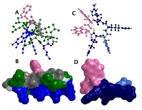
We utilized epifluorescence microscopy to study the morphological changes associated with the interaction of model antimicrobial peptides with lipid bilayers supported on quartz substrates and doped with NBD-DPPE or Rh-DPPE labelled lipids. Two antimicrobial peptides were used, the cyclic hexapeptide C-RW and the amphipathic helical peptide KLA1. The amphipathic structure of both peptides is illustrated in Figure 1.
Figure 1.
An illustration showing the amphipathic structure of the helical KLA1 (A and B) and of the cyclic hexapeptide C-RW (C and D), where the basic amino acids are oriented in one direction and the hydrophobic residues are aligned in the opposite direction. In the side view (A and C) as well as the Connolly surface (B and D), lys (K) is coloured blue, arg (R) is coloured dark blue, leu (L) is coloured green, ala (A) is coloured grey, trp (W) is coloured pink, phe (F) is coloured sky blue, and the backbone is coloured light gray.
KLA1 (KLAL KLAL KAW KAAL KLA-NH2) as well as some other KLA peptides were synthesized and investigated as described before.24-29 KLA1 (see Figures 1A and 1B) is composed of 18 amino acids (5 lys, 6 leu (L), 6 ala (A), and 1 trp (W) residues), where the N-terminus is uncapped and the C-terminus is amidated. The peptide has a nominal charge of +6 provided by the 5 lys residues and the uncapped N-terminus, while the leu, ala, and trp groups form the hydrophobic part of the amphipathic peptide. Generally, the KLA peptides are unstructured in buffer, whereas they assume an α-helical amphipathic structure in TFE (trifluoroethanol) or when bound to negatively charged lipid vesicles or to lipid monolayers. The KLA peptides exhibit substantial antimicrobial and membrane permeabilizing activities, however, they are poorly selective, as evident by their high haemolyses and permeabilizing activity on uncharged vesicles. C-RW (cyclo-RRWWRF) peptide (see Figures 1C and 1D) was introduced by a head-to-tail cyclization of the linear sequence, i.e. Ac-RW (Ac-RRWWRF-NH2).30,31 The cyclization enhances the antimicrobial activity and selectivity of the peptide. In these peptides, arg provides the positive charge and the capacity for hydrogen bonding, while the hydrophobic bulky amino acid trp has a preference for the interfacial region of the bilayer allowing a prolonged attachment and a deeper burial in the membrane.5,32 C-RW displays an amphipathic ordered structure in solution and even a more well-defined structure in the vesicle bound state.30,33 A recent DSC (differential scanning calorimetry) and FT-IR (Fourier transform infrared) study showed that C-RW and Ac-RW induce a demixing in DPPG/DPPE membranes and leads to the formation of two domains, a DPPG-peptide domain and a peptide-poor DPPE-enriched domain. This phenomenon is not observed in DPPG/DMPC membranes where the peptides only cause a substantial down-shift in the transition temperature of the mixtures.17
To mimic the relevant biological membranes, we investigated the influence of the peptides on supported membranes of POPG, POPC, POPE, POPG/POPC, and POPG/POPE as well as Escherichia coli (E. coli) lipid extract (67% PE, 23.2% PG, 9.8% CL).
2. Experimental procedures
2.1. Materials
2.1.1. Peptides
The synthesis of KLA1 (KLAL KLAL KAW KAAL KLA-NH2) and CRW (cyclo-RRWWRF) was described before.25,30,31 The peptide solutions were freshly prepared in an aqueous Tris (Tris-(hydroxymethyl) aminomethane) buffer by weighing the lyophilized samples, dissolving them in buffer, and diluting the samples to the required concentration.
2.1.2. Lipids
1-palmitoyl-2-oleoyl-sn-glycero-3-phosphoglycerol (POPG), 1-palmitoyl-2-oleoyl-sn-glycero-3-phosphocholine (POPC), 1-palmitoyl-2-oleoyl-sn-glycero-3-phosphoethanolamine (POPE), 1,2-dipalmitoyl-sn-glycero-3-phosphoethanolamine-N-[7-nitro-2-1,3-benzoxadiazol-4-yl] (NBD-DPPE), 1,2-dipalmitoyl-sn-glycero-3-phosphoethanolamine-N-[lissamine rhodamine B sulfonyl] (Rh-DPPE), and E. Coli polar lipid extract (67% PE, 23.2% PG, 9.8% cardiolipin) were purchased from Avanti Polar Lipids (Alabaster, AL, USA). All lipids were used as received without any further purification or modification. The concentration was calculated from the weight of the dry lipid samples (w/v).
2.2. Methods
2.2.1. Planar supported lipid bilayers
For the epifluorescence microscopy and FRAP experiments, quartz slides (40 mm × 25 mm × 1 mm) were purchased from Quartz Scientific (Fairport Harbor, OH). The following steps were used to clean the slides: 1) boiling in 10% Contrad 70 detergent (Fisher Scientific, Fair Lawn, NJ) for 10 min, 2) hot bath sonication in the detergent solution for 30 min, 3) thorough rinsing with Milli-Q water, 4) immersion in 95% H2SO4/30% H2O2 (Fisher Scientific, Fair Lawn, NJ) 3:1 mixture for 30 min to remove any organic residues, 5) extensive rinsing with Milli-Q water, and 6) the slides were kept in deionised water ready for use. Immediately prior to use, the slides were further cleaned for 5-10 min in an argon plasma sterilizer (Harrick Scientific, Ossining, NY).
The supported planar bilayers were prepared by either one of three different methods34,35: vesicle fusion36, Langmuir Blodgett/Langmuir Schaefer22, or combined Langmuir Blodgett/vesicle fusion37.
2.2.1.1. Vesicle fusion (VF)
the desired lipids or lipid mixtures were co-solved with 1% NBD-DPPE in chloroform/methanol (Fisher Scientific, Fair Lawn, NJ) mixture. Thereafter, the solvent was evaporated under a stream of N2 and kept under vacuum for at least 1 hour. The lipid film was suspended in aqueous Tris buffer (10 mM Tris/Tris-HCl (Sigma, St. Louis, MO), 154 mM NaCl (Sigma, St. Louis, MO), pH 7.4) and the suspension was extruded through two polycarbonate filters with 100 nm pore size to produce LUVs of 100 nm diameter. A clean quartz slide was placed in a custom-built flow-through chamber. 1.2 ml of 100 μM suspension of LUVs was injected into the chamber and incubated for 30 to 60 min for the supported bilayer to form. The excess vesicles were flushed by rinsing the chamber with Tris buffer. If necessary, the lipid vesicles were premixed with CaCl2 (Fisher Scientific, Fair Lawn, NJ), as a source for calcium ions, to achieve a final concentration of 0.2 to 1 mM. Subsequently, the excess vesicles and calcium were washed out using buffer containing ~ 20 mM EDTA (Fisher Scientific, Fair Lawn, NJ).
2.2.1.2. Langmuir Blodgett/Langmuir Schaefer (LB/LS)
prior to each preparation, a Nima 611 Langmuir Blodgett trough (Nima, Coventry, U.K.) was rinsed extensively with distilled water. The trough was filled with deionised water and the lipid films were prepared at room temperature. A lipid monolayer containing 0.75% NBD-DPPE or Rh-DPPE was spread from chloroform/methanol solution on the water surface to achieve a starting surface pressure of 0 to 5 mN m−1. The film was given ~ 10 min to equilibrate and for the solvent to evaporate entirely. Thereafter, the film was compressed with a speed of 15 cm2 min−1 to reach a surface pressure of ~ 32 mN m−1. Again, the film was given 10 min to equilibrate while the software maintained the surface pressure constant at 32 mN m−1. A freshly cleaned quartz slide was rapidly (200 mm min−1) dipped into the trough and slowly (5 mm min−1) withdrawn, while the surface pressure was maintained at 32 mN m−1, thereby depositing a LB monolayer film on both sides of the glass slide. The LS film transfer was then achieved by contacting the LB monolayer coated slide with its face downward with another lipid monolayer on the surface of the trough. A suctioning tip was used to hold the slide. Once contact had been made, the slide was pushed through the surface and position in the bottom half of the flow-through chamber, which had been positioned before in the trough underneath the lipid film. The chamber was assembled and sealed under water to prevent air bubbles from entering the chamber. After removal from the trough, the water in the chamber was carefully exchanged with Tris buffer.
2.2.1.3. Langmuir Blodgett/vesicle fusion (LB/VF)
after an LB-coated slide was prepared and placed in the flow-through chamber, the vesicle suspension was injected into the chamber, incubated, and then rinsed as previously described.
2.2.2. Fluorescence microscopy
The epifluorescence imaging was carried out at room temperature using two fluorescence microscope setups as described previously38-40: 1) A Zeiss Axiovert 35 fluorescence microscope (Carl Zeiss, Thornwood, NY) with a 40× water immersion objective (Zeiss; numerical aperture (N.A.) 0.75) was used and the images (520×688 pixel2, 105×139 μm2) were recorded by a charge-coupled device (CCD) cooled to −12°C (Sensicam QE, Cooke, Auburn Hills, MI). For epifluorescence imaging, NBD-DPPE-labelled bilayers were excited with a mercury lamp through a 436 nm band-pass filter (D436/10, Chroma) and observed through a 535 nm band-pass filter (D535/40, Chroma). For FRAP experiments, NBD-DPPE was excited by an argon ion laser (Innova 300C, Coherent, Palo Alto, CA) at 488 nm and observed through a 535 nm band-pass filter (D535/40, Chroma). The intensity of the laser beam was computer controlled by an acousto-optic modulator (AOM-40, IntraAction, Bellwood, IL) or could be blocked entirely by a computer-controlled shutter. Fluorescence emission intensity was measured using a photomultiplier tube (Thorn EMI 9658A, Ruislip, UK). 2) A Zeiss Axiovert 200 fluorescence microscope (Carl Zeiss, Thornwood, NY) with a 63x water immersion objective (Zeiss; numerical aperture (N.A.) 0.95) was used and the images (512×512 pixel2, 128×128 μm2) were recorded by an electron multiplying charge-coupled device (EMCCD) cooled to −60 °C (iXon DV887AC-FI, Andor, Belfast, UK). NBD-DPPE-labelled bilayers were excited with a mercury lamp through a 480 nm band-pass filter (D480/30, Chroma) and observed through a 535 nm band-pass filter (D535/40, Chroma). Movies from Rh-DPPE-labelled bilayers were recorded using an argon ion laser (Innova 90C-5, Coherent) tuned to 514 nm as light source. Fluorescence light was separated from the excitation light by a dichroic mirror (565dclp, Chroma) and passed through a bandpass filter (D605/55, Chroma). Data acquisition and image analysis on both setups were done using homemade software written in LabView (National Instruments, Austin, TX). Further image processing, such as cropping, scaling and colouring of the images, were performed using Adobe® Photoshop® and ImageJ.
2.2.3. Procedure for peptide addition
The peptide solutions with the desired concentration (usually 1 – 5 μM) were prepared in an aqueous Tris buffer. The buffer inside the ~ 1 ml flow-through chamber was replaced with the peptide solution as follows. The chamber is rectangular in shape and has two openings at two opposite corners. A 1 ml syringe was filled with the peptide solution which was gently injected into one of the openings of the chamber with a speed around 100 μl sec−1, and the overflow was carefully removed using a suction tip.
2.2.3. Fluorescence recovery after photobleaching (FRAP)
In the FRAP experiments38,39,41 the NBD-DPPE labelled lipid bilayers were bleached with a pattern of parallel stripes42. At least ten different regions were examined to determine the lateral diffusion constant and the percentage of fluorescence recovery of the supported bilayer.
3. Results
Supported planar membranes were prepared by one of three methods35: vesicle fusion (VF)36, Langmuir Blodgett/Langmuir Schaefer (LB/LS)22, or combined Langmuir Blodgett/vesicle fusion (LB/VF)37. The preparation of uncharged and moderately charged supported membranes is relatively uncomplicated. However, bacterial membranes are rich in negatively charged lipid components, particularly PG. Consequently, the incorporation of high amounts of PG in our model membranes is the main obstacle in producing the supported membranes.
It was necessary to find protocols to efficiently produce supported bilayers of our lipids of interest. The stability, integrity, and reproducibility of the SLBs were checked and the quality of the produced SLBs was examined visually by epifluorescence microscopy and also by means of fluorescence recovery after photobleaching (FRAP)41. FRAP was used to determine the lateral diffusion coefficient of labelled lipids in the SLBs, in order to check the fluidity and continuity of the membrane.
3.1. Vesicle fusion and Langmuir Blodgett/vesicle fusion techniques
The combined LB/VF technique failed to produce SLBs of lipid preparations rich in POPG. The reason is that the first LB monolayer is highly unstable when in contact with buffer. Also, without the use of fusogenic agents no SLBs rich in POPG can be obtained by the VF method, because the electrostatic repulsion between POPG and the negatively charged quartz substrate hampers proper adsorption of the anionic lipid vesicles.
The utilization of divalent cations, particularly calcium, is a common method to aid the adsorption of lipid vesicles on substrates and their rupture to supported membranes.20,37,43-45 The premixing of calcium with vesicles containing low amounts of POPG facilitates the formation of SLBs. However, the premixing of calcium with pure POPG vesicles only enhanced their adsorption onto the quartz surface, but the vesicles did not rupture and remained intact as proven visually under the microscope, i.e., no uniform bilayer but vesicle aggregates scattered over the quartz support, and by FRAP experiments (data not shown).
The presence of calcium in our buffer system was expected to interfere with the binding of our cationic peptides to the lipid bilayers. In addition, calcium may induce the aggregation and possibly the fusion of the PG containing lipid vesicles, which is already a known effect of divalent cations on acidic membranes,46-49 and the effects of calcium and of the antimicrobial peptides would be superimposed. Therefore, we had to find other techniques to prepare our SLBs without the use of any interfering substances.
Interestingly, the premixing of the cationic C-RW (no calcium) with POPG-containing vesicles facilitates the adsorption and rupture of the vesicles and the formation of the SLBs (data not shown). Nonetheless, it is not possible to produce “control” SLBs by the VF technique without the use of peptides or calcium.
3.2. Langmuir Blodgett/Langmuir Schaefer technique
With the utilization of Langmuir Blodgett/Langmuir Schaefer (LB/LS) method, we could successfully prepare SLBs of pure POPG and POPG-rich membranes without the need to use any fusogenic agents. The bilayers were produced using lipid monolayers whose surface pressure was maintained constant at 32 mN m−1, which is the so-called monolayerbilayer equivalence pressure.21,50
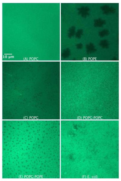
Figures 2A to F show the epifluorescence images of the SLBs of POPC, POPE, POPG, POPG/POPC 1:1, POPG/POPE 1:1, and E. coli lipid extract, respectively. The lipid preparations were premixed with 0.75 mol% NBD-DPPE, which preferentially partitions into fluid (liquid crystalline) bilayer phases51. The FRAP data prove the fluidity and continuity of the prepared SLBs (see supplementary material). The lateral diffusion coefficient of NBDDPPE in the SLBs is in the order of μm2 s−1 in accordance with that of fluid phase membranes41, which also proves that NBD-DPPE is indeed in the fluid phase.
Figure 2.
SLB prepared by LB/LS transfer of the pure lipids POPC (A), POPE (B), POPG (C), POPG/POPC 1:1 (D), POPG/POPE 1:1 (E), and E. coli lipid extract (F). The lipids were premixed with 0.75 mol% NBD-DPPE. The dark areas represent dye-depleted domains.
The SLB of POPC (Figure 2A) is uniformly bright due to the homogeneous distribution of the fluorescent dye in the bilayer. The epifluorescence image of POPE (Figure 2B), whose phase transition is around room temperature (~ 25°C,52), exhibits dye-depleted lipid domains. We believe that the dark areas represent the POPE ordered phase, from which the fluorescent dye molecules are excluded. Dark domains are commonly observed in monolayers and bilayers of lipids in the liquid-condensed or gel state, respectively.53,54
Interestingly, the epifluorescence image of the POPG (Figure 2C) shows small, uniformly distributed dark domains. Due to the fluid nature of POPG and similarly to POPC, it was expected that the structure of the SLB of POPG would look similar to that of POPC. Furthermore, no such dark domains were observed with POPG monolayers prepared by Langmuir Blodgett method but rather a bright epifluorescence image as observed with the POPC SLB (data not shown). Therefore, we believe that the interaction of POPG in the supported bilayer with the quartz surface induces the formation of ordered domains. Nonetheless, the possibility that some of the dark domains are due to bilayer imperfections cannot be ruled out.
The structure of the supported membranes of POPG/POPC 1:1 and POPG/POPE 1:1 lipid mixtures are depicted in Figure 2D and Figure 2E, respectively. Both bilayers show the presence of small dark domains, which are expectedly much smaller in the case of the POPG/POPC 1:1 lipid mixture as compared to POPG/POPE 1:1 lipid mixture. The epifluorescence image of E. coli lipid extract (Figure 2F) shows a more complicated membrane structure, which is most probably associated with the complex composition of the lipid extract. As seen, for instance, in Figures 2E, 6A and 9A some dye molecules cluster at the boundaries between the ordered and disordered domains.
Figure 6.
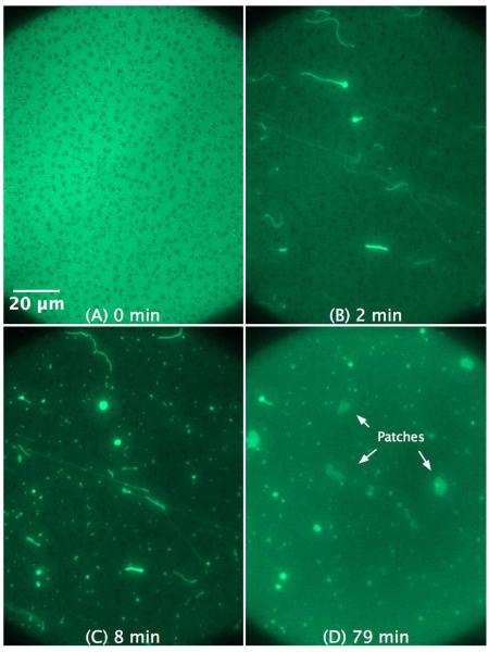
SLB prepared by LB/LS transfer of POPG/POPE 1:1 (NBD-DPPE 0.75 mol%). The figures illustrate the effect and morphological changes that occur over time (0 to 79 min) after the addition of 4 μM C-RW into the buffer.
Figure 9.
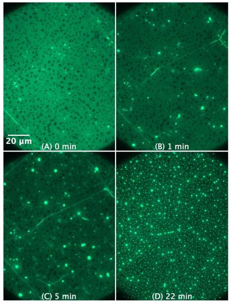
SLB prepared by LB/LS transfer of POPG (NBD-DPPE 0.75 mol%). The figures illustrate the effect and morphological changes that occur over time (0 to 22 min) after the addition of 4 μM KLA1 into the buffer. The bright lines in the SLB shown in (B) and (C) are most probably membrane deformations that were initially formed during the peptide injection process.
One of the most significant observations is the trans-membrane domain coupling between both lipid leaflets of the supported membrane, i.e. both monolayers share the same ordered dye-depleted domains (see Figure 2). This phenomenon indicates the strong influence each lipid monolayer has on the other monolayer. The trans-membrane coupling of monolayers on bilayers was investigated before for cholesterol rich lipid ordered domains in asymmetric SLBs.38,40,55 It was found that the cholesterol rich liquid ordered domains in one leaflet could induce lipid ordered domains in the opposite asymmetric leaflet when this leaflet was composted of certain lipid species.
3.3. The interaction of C-RW with SLBs prepared by LB/LS
For studying the interaction of the peptides with the SLBs, the buffer inside the chamber was replaced with the peptide solution with the desired concentration (see methods). The peptide addition was performed carefully and slowly enough in order not to disturb the lipid membrane, and control experiments were performed to validate this. Since the peptides interact readily and strongly with the lipid membranes, imaging of the labelled SLBs was usually performed near the location of the peptide injection, where the effect of the peptides on SLBs would more likely take place. The injection procedure may have caused a higher peptide accumulation on the SLB near the injection point as compared to the rest of the SLB, which led not only to more frequent but also to more pronounced peptide/lipid interactions. The peptide-induced morphological changes were reproducible as well as observed in other places on the SLBs, however, less frequently. The figures shown in this study are representative of the observed effects of the peptides on the various SLBs, and emphasize the effect of local peptide concentration.
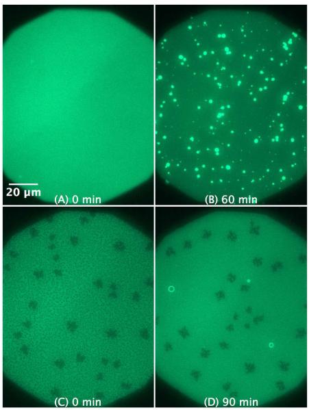
Up to ~ 1 hour after addition, C-RW does not show any influence on the SLBs of the uncharged lipids POPC and POPE (data not shown). However, its action on the negatively charged SLBs is rapid (within a few minutes) and dependent upon the peptide concentration and the surface charge density, i.e., POPG fraction in the membrane.
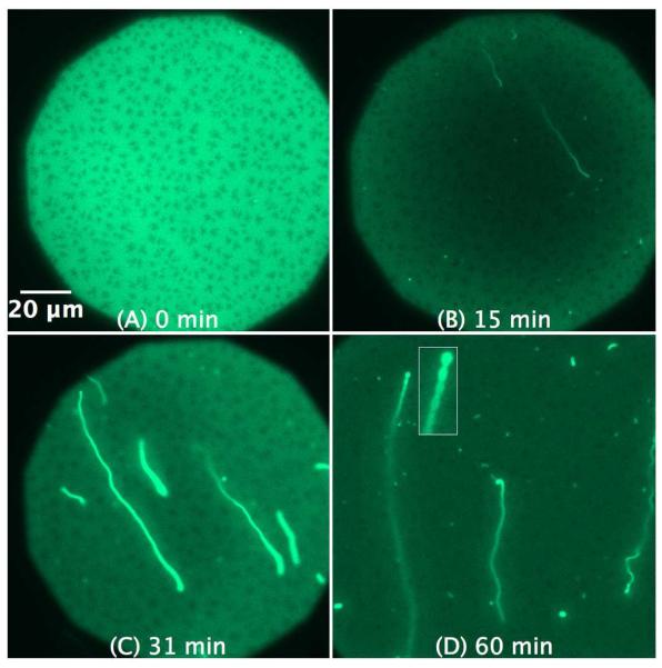
As demonstrated in Figure 3, the interaction of 1 μM C-RW with POPG SLB triggers the formation of bright fibrils within minutes, which continue to grow in size and length over time. The fluorescent fibrils bulge out of the SLB plane into the bulk, whereas the brighter spots of the structures remain in focus and indicate where the fibrils are attached to the supported membrane. In addition, the fibrils show floating ends with high flexibility as evident by their rapid Brownian movement in bulk (visible in the time dependent images, see Movies 1a and b in the supplementary material). After ~ 1 hour, the length of some fibrils exceeds 100 μm, whereas their apparent width varies from 1 to 4 μm. These fibrils are apparently lipid tubules extending from the SLBs into the bulk solution. Despite the high loss of lipid material from the SLBs upon the formation of μm-size tubules, an observation that was reported before in a recent study43, no membrane breakdown or large membrane defects were observed. This is probably due to lipid redistribution in the SLB that compensates for the lipid loss and helps covering the empty gaps with lipid as well as dye molecules. Furthermore, the technique we use here is not suitable to comment on any changes in the lipid density or membrane inhomogeneity on a small scale.
Figure 3.
SLB prepared by LB/LS transfer of POPG (NBD-DPPE 0.75 mol%). The images illustrate the effect and morphological changes that occur over time (0 to 60 min) after the addition of 1 μM C-RW into the buffer. The subsequent images became darker as compared to the control image due to the photobleaching effect. The inset in (D) is a magnification of the pearl-chain instability.
Another interesting observed phenomenon is the peptide-induced formation of pearl-chain instabilities (Figure 3D), where a chain of vesicles is connected to each other through small bilayer tubes. Such instabilities have been widely studied experimentally and are formed when a sudden tension is applied upon lipid membranes, for instance through laser tweezers, osmotic perturbations, bilayer asymmetry, and anchoring of amphipathic molecules.56,57
The lipid fibrils look much brighter than the rest of the membrane. We believe that this observation is due to the following: the SLBs are only 4 nm thick, whereas the fibrils extend much more in the z direction. The x/y plane of the focal area is fixed whereas the focal area extends hundreds of nanometers in the z direction, therefore, much more membrane from the protrusions can be seen as compared to the 4 nm thick SLB and this makes the fibrils look brighter.
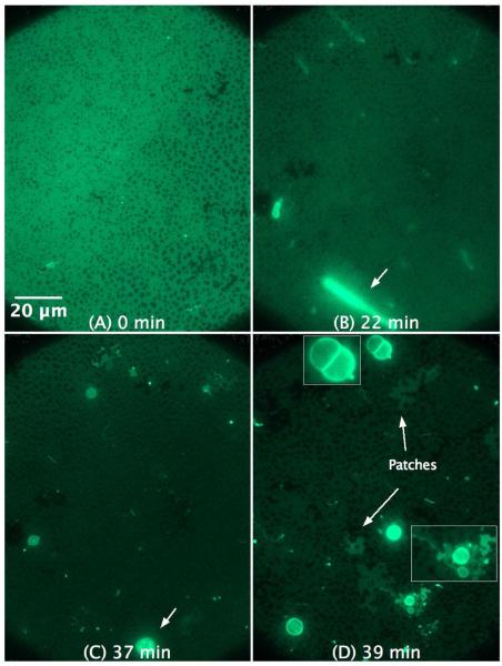
Increasing the concentration of C-RW to 4 μM strongly alters the effect of the peptide on the POPG SLB (Figure 4). The action of the peptide becomes faster, while the fibrils do not grow but rather transform into giant spherical structures, probably vesicles (compare Figure 4B and Figure 4C). The diameter of some of the formed vesicles is larger than 6 μm. Several giant structures rupture and flatten on the SLB distal surface leaving patches of irregular structures (see Figure 4D), which can be easily distinguished from other places on the SLB where no patches are adsorbed to the distal leaflet.
Figure 4.
SLB prepared by LB/LS transfer of POPG (NBD-DPPE 0.75 mol%). The figures illustrate the effect and morphological changes that occur over time (0 to 39 min) after the addition of 4 μM C-RW into the buffer. The subsequent images became darker as compared to the control image due to the photobleaching effect. The insets in (D) are magnifications of some structures in the image.
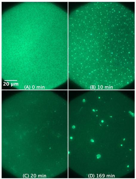
The C-RW-induced morphological changes in the SLBs with mixed lipids, i.e., of POPG/POPC 1:1 and POPG/POPE 1:1 lipid mixtures, are somewhat different from that induced in the SLB of pure POPG. As shown in Figure 5, 4 μM C-RW provokes the formation of numerous small protrusions (~ 1 μm) in the SLB of a POPG/POPC 1:1 mixture. The protrusions continue to grow and form longer fibrils, but they are still much smaller as observed with pure POPG. In Figure 5C, one can observe some fibrils that are detached from the membrane surface and are floating in the bulk adjacent to the SLB. Over longer time, the fibrils merge to produce giant spherical structures of a few micrometers in diameter (see Figure 5D). Interestingly, the C-RW peptide causes the ordered-domains in the SLB of POPG/POPC 1:1 mixture to disappear. This is most probably due to the fluidizing effects the peptide has upon its insertion into the membrane headgroup-acyl chain interface region, which is in a good agreement with the published results.17,32 Movie 2 in the supplementary material shows time-dependent images taken over ~ 1 hour right after the addition of 4 μM CRW to POPG/POPC 1:1. Rh-DPPE was utilized to label the SLBs when movies were taken, as Rh-DPPE is less susceptible for photobleaching as compared to NBD-DPPE. Movie 2 shows the fast action of C-RW, which induces the formation of many thin fibrils that float in the bulk. Some fibrils transform into spherical structures, and many of the formed structures detach from the membrane.
Figure 5.
SLB prepared by LB/LS transfer of POPG/POPC 1:1 (NBD-DPPE 0.75 mol%). The figures illustrate the effect and morphological changes that occur over time (0 to 169 min) after the addition of 4 μM C-RW into the buffer.
The interaction of C-RW with POPG/POPE 1:1 causes the growth of mid-size fibrils (Figure 6), i.e., smaller than in the case of POPG but larger than those observed for POPG/POPC 1:1 SLBs. The fibrils transform over time into bulkier structures, where some structures rupture and flatten on the distal surface leaving patches on the supported membrane (see Figure 6D). Similarly to what was observed in the SLB of POPG/POPC 1:1 mixture, CRW fluidizes the ordered domains in the SLBs of POPG/POPE 1:1, as they disappear over time (see Figure 6). The membrane fluidizing effect of C-RW as well as the formation of lipid fibrils, the structural transformations over time, and the formation of lipid patches on the membrane distal leaflet can be clearly seen in Movie 3 in the supplementary material.
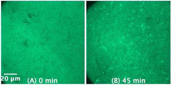
To investigate the antimicrobial action of the peptides on membranes with a composition resembling a natural membrane, we performed the experiments on the SLB of E. coli lipid extract (Figure 7). The effect of C-RW on the E. coli membrane is comparable to model supported membranes, yet, slower and less massive. This might be explained by the low PG content in the E. coli lipid extract. As one can see in Figure 5B and Figure 6C the origin of the structures bulging out from the supported bilayers is frequently close to the boundaries of the ordered lipid domains. A similar observation has been reported before58, and this could be due to a higher accumulation of the peptide at the domain boundaries and to that it is easier to strip off the lipid bilayer from the substrate at the domain boundaries. This may explain why less fibrils are formed in the SLBs of POPG and POPG/POPE 1:1 as compared to that of POPG/POPC 1:1 and E. coli, since the ordered domains in the former SLBs are larger and less frequent in comparison to the latter SLBs.
Figure 7.
SLB prepared by LB/LS transfer of E. coli lipid extract (NBD-DPPE 0.75 mol%) before (A) and 45 min after the addition of 1.2 μM C-RW into the buffer (B).
3.4. The interaction of KLA1 with SLBs prepared by LB/LS
KLA1 belongs to the class of peptides forming amphipathic α-helices when bound to negatively charged lipid bilayers or monolayers. Therefore, it is to be expected that the morphological changes observed upon interaction with SLBs might be different compared to the much smaller cylic hexapeptide C-RW. The interaction of KLA1 with the uncharged SLBs of POPC (Figures 8A and 8B) and POPE (Figures 8C and 8D) slowly induces the formation of structural protrusions indicating the incorporation of KLA1 and the subsequent perturbation of the bilayers. The effect on POPE membranes is much weaker compared to POPC, which can be explained by the preference of POPE for a negative spontaneous curvature as compared to POPC. The observations that KLA1 also disturbs uncharged lipid membranes agree well with the poor selectivity of KLA peptides observed with biological and model membranes.25,26
Figure 8.
SLB prepared by LB/LS transfer of POPC (left) and POPE (right) (NBD-DPPE 0.75 mol%) before (A and C, respectively) as well as 60 and 90 min after the addition of 4 μM KLA1 into the buffer (B and D, respectively).
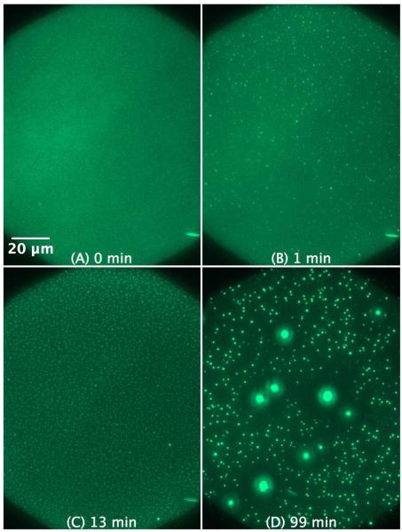
With POPG more pronounced effects are to be expected. As shown in Figure 9, the influence of KLA1 on the POPG SLB is drastically different from the effect of C-RW. The morphological changes occur now much faster as compared to POPC and POPE SLBs, but KLA1 does not induce long fibrils but rather small local protrusions. The induced protrusions do not coalesce into giant vesicular structures as in the previous case when C-RW was used.
The action of KLA1 on the SLB of a POPG/POPC 1:1 mixture (Figure 10) is comparable to that of POPG, however, the protrusions are even smaller but more frequent. Moreover, some of the protrusions form larger structures over time. Movie 4 in the supplementary material shows the fast morphological changes induced by KLA1 on the SLB of POPG/POPC 1:1, which actually takes place immediately after the injection process. The fibrillar protrusions quickly transform into spherical structures and many disappear over time by either budding out of the SLB completely or fusing back to the SLB.
Figure 10.
SLB prepared by LB/LS of POPG/POPC 1:1 (NBD-DPPE 0.75 mol%). The figures illustrate the effect and morphological changes that occur over time (0 to 99 min) after the addition of 4 μM KLA1 into the buffer.
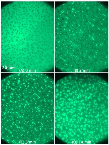
The protrusions formed in the SLB of POPG/POPE 1:1 mixture by addition of KLA1 (Figure 11) are larger and mostly originate again from the boundaries of the ordered domains. Interestingly, the protrusions seem to flatten out after a while and acquire irregular shapes lying flat on the surface. The formation of these distinctive structures is shown in Movie 5 in the supplementary material. Similarly to what was observed before with C-RW, KLA1 also causes the disappearance of the dark areas in the SLB of POPG/POPE 1:1 mixture.
Figure 11.
SLB prepared by LB/LS of POPG/POPE 1:1 (NBD-DPPE 0.75 mol%). The figures illustrate the effect and morphological changes that occur over time (0 to 14 min) after the addition of 4 μM KLA1 into the buffer.
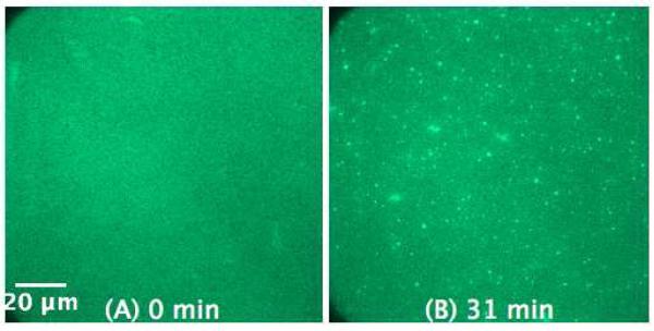
The influence of KLA1 on the SLB of E. coli lipid extract (Figure 12) is relatively weak as compared to the other model SLBs. Again, this can be explained by the lower charge content of the E. coli membrane.
Figure 12.
SLB prepared by LB/LS of E. coli lipid extract (NBD-DPPE 0.75 mol%) before (A) and 31 min after the addition of 5 μM KLA1 into the buffer (B).
4. Discussion and Conclusions
We investigated using epifluorescence microscopy the structure of solid supported membranes on quartz slides of various lipids and lipid mixtures before and after binding of the antimicrobial peptides C-RW and KLA1. The solid supported membranes consisted of pure POPG and of POPG rich lipid mixtures. Due to the high PG content in our model membranes, the Langmuir Blodgett/Langmuir Schaefer technique was the only possible method to prepare the corresponding SLBs. The method was also appealing since the utilization of fusogenic agents such as calcium was not necessary. To our knowledge, pure POPG supported membranes could not be obtained before, so that the method presented here is the only successful one for the preparation of pure PG membranes and can also be used for the preparation of SLBs rich in POPG.
The action of the membrane active peptides C-RW and KLA1 is quick (few minutes) and driven first by electrostatic binding to the negatively charged membrane surface. The electrostatically driven preferential interaction of our peptides with negatively charged lipid mono- and bilayers has been shown in earlier studies.25,27,30 The subsequent interaction via hydrophobic residues in the peptides with the lipid bilayer triggers the formation of lipid protrusions that bulged out of the SLBs as seen by time-lapse fluorescence microscopy. The protrusions seem to grow particularly from the domain boundaries and membrane defects. Whereas C-RW facilitates the formation of long fibrils, KLA1 induces smaller membrane structures. The long lipid protrusions tend to restructure into spherical structures over time, which was also observed in another study59. This behaviour could be because the spherical structures were energetically more favourable than the tubular protrusions, and in lipid mixtures this may be associated with redistribution of lipids in the membrane.
Significant differences in morphological changes are observed between mixed POPG/POPC and POPG/POPE membranes. POPE prefers due to its smaller headgroup a negative curvature at the membrane interface. In a mixture of POPE with POPG, a lipid with positive curvature tendency, the formation of flat structures is preferred. This can be seen after addition of both peptides where after the induction of protrusions the formation of flat structures, seen as patches on the SLB, seems to take place, whereas in POPG/POPC mixtures small spherical structures or even larger vesicles seem to appear. The transformation from vesicular to flat structures in PG/PE membranes was reported before, where the antimicrobial peptide LL-37 was found to destroy DPPG/DPPE vesicles forming a stack of planar bilayer fragments.60 Again, this phenomenon was not observed with DPPG/DPPC vesicles, being another example on the differences in the behaviour between PG/PE and PG/PC membranes.
Also, small differences in the behaviour of C-RW and KLA1 are observed. For instance, in contrast to C-RW KLA1 induced, though moderately, the formation of lipid protrusions in the uncharged SLBs of POPC and POPE. These differences are most probably due to their different mode of action; KLA1 is poorly selective and has a higher affinity to uncharged membranes as compared to C-RW. In addition, C-RW is smaller and interacts preferentially with the membrane interfacial region, whereas KLA1 is buried deeper in the membrane hydrophobic core and thereby capable of disturbing the lipid membrane more pronouncedly.
Previously we found by DSC and by FT-IR-spectroscopy that C-RW induces an extensive lipid demixing in the gel-state DPPG/DPPE mixtures. The demixing causes the formation of DPPG-C-RW domains and DPPE-enriched domains without peptide.17 The question was whether a similar phenomenon can also occur in fluid POPG/POPE mixtures. In this case it can be expected that the domains must be much smaller. The epifluorescence images do not reveal any lipid demixing in the POPG/POPE mixture. Nevertheless, the interaction of C-RW with POPG/POPE mixtures may have caused local lipid demixing leading to some of the observed behaviour of the formation of protrusions, because of the local separation of PG with bound peptide preferring positive curvature, but the peptide-induced domains formed in POPG/POPE mixtures are probably too small to be seen with the epifluorescence microscopy as stated above.
The peptide-induced demixing in fluid membranes is not unrealistic and could recently be visualized in POPE/TOCL (tetraoleyl cardiolipin) SLBs using combined atomic force and fluorescence microscopy.23 Freeze fracture electron microscopy showed membrane deformations and suprastructures in POPE/TOCL vesicles after the addition of some antimicrobial peptides, a phenomenon that was attributed to peptide-induced clustering of lipid molecules.61
The formation of fibrillar structures induced by antimicrobial peptides was observed before with SLBs43,58 and giant unilamellar vesicles (GUVs)59,62. In the case of GUVs the peptides may also lead to the budding of smaller vesicles and shrinking of the GUV, and if peptide concentration is high enough the GUV may burst and disintegrate.59,62,63
Domanov et al. (2006) used additionally fluorescent labelled peptides, so that they could conclude that the fibrils were composed of both lipids and amphipathic peptides. Furthermore, they demonstrated that the fibrils were tubular structures formed of lipid bilayers rather than long cylindrical micelles. Domanov et al. proposed two ways to relieve the increased lateral pressure profile across the lipid monolayer upon the binding of an amphipathic peptide; 1) monolayer dilation and membrane thinning, and 2) the formation of protrusions which takes place at higher peptide concentrations.58 Recently, a specific mode of action of a cyclic peptide on membranes could be identified by coarse-grained MD simulations.64 When the cyclic octapeptide RRKWLWLW is bound to POPG/POPE membranes it causes a drastic change in the lateral pressure profile leading not only to changes in the mechanical properties of the bilayer but also to a possible buckling of the membrane. At higher concentrations, amphipathic nanotubes are formed by the peptide at the membrane interface. The coating of the membrane causes then extrusion of lipids from the exposed bilayer leaflet, leading ultimately to a release of phospholipid micellar aggregates. Whereas this result maybe a specific effect of the used cyclopeptide, other effects, i.e., membrane deformation and formation of membrane protrusions leading to morphologic changes such as lipid tubule formation and budding of vesicles, might be general phenomena occurring after the binding of amphipathic peptides to membranes.
Generally, the peptide-induced structures and the morphological changes that take place are controlled by the following factors, namely 1) shape and size of the peptide, 2) peptide concentration, 3) membrane composition, 4) surface charge density, 5) state of the lipid molecules (gel or fluid), 6) geometry of the lipid components, which could favour positive or negative curvatures, and 7) peptide-induced domain formation. However, further investigations are necessary to obtain additional information about, for instance, the lipid/peptide ratio and lipid composition in the lipid protrusions as compared to the SLB as well as the role of lipid redistribution, if any, in the lipid membrane in order to realize the observed protrusions and structures.
As discussed above, our previous experiments with lipid bilayers and monolayers showed the high affinity of the peptides to integrate into lipid membranes; KLA1 is buried deeper in the membrane hydrophobic core whereas C-RW stays at the headgroup/acyl chains interface. In term of the mechanism of action in membranes, at low concentrations KLA1 as a helical peptide may induce the formation of transmembrane pores6,65 whereas C-RW may cause demixing in the lipid membrane without affecting the membrane integrity17,66, both effects will disturb the membrane functionality. At high concentrations both amphipathic peptides have the capacity to disintegrate lipid membranes.
The current study with SLBs demonstrates the destructive nature of antimicrobial peptides on lipid membranes, which is a realization of the various mechanisms of action described in literature, e.g. membrane micellization (carpet model), lipid demixing, domain formation, and the induction of non-lamellar structures. Such morphological changes may significantly alter the functionality of bacterial membranes, however, the biological relevancy of these phenomena, particularly for the antimicrobial activity of the peptides, should be verified.
Supplementary Material
Acknowledgement
This project was financially supported by the Deutsche Forschungsgemeinschaft through the Graduiertenkolleg “Conformational Transitions in Macromolelcular Interactions” (GRK 1026) and by NIH grant R37 AI030557.
Footnotes
Supplementary information available: FRAP curves and movies made of time dependent images showing the effect of the antimicrobial peptides on labelled supported lipid membranes of some of the lipid systems discussed above as well as the induced morphological changes. This material is available free of charge via the Internet at http://pubs.acs.org.
References
- (1).Gordon YJ, Romanowski EG, McDermott AM. Curr. Eye Res. 2005;30:505. doi: 10.1080/02713680590968637. [DOI] [PMC free article] [PubMed] [Google Scholar]
- (2).Radek K, Gallo R. Semin. Immunopathol. 2007;29:27. doi: 10.1007/s00281-007-0064-5. [DOI] [PubMed] [Google Scholar]
- (3).Bechinger B, Lohner K. Biochim. Biophys. Acta. 2006;1758:1529. doi: 10.1016/j.bbamem.2006.07.001. [DOI] [PubMed] [Google Scholar]
- (4).Brogden KA. Nat. Rev. Microbiol. 2005;3:238. doi: 10.1038/nrmicro1098. [DOI] [PubMed] [Google Scholar]
- (5).Chan DI, Prenner EJ, Vogel HJ. Biochim. Biophys. Acta. 2006;1758:1184. doi: 10.1016/j.bbamem.2006.04.006. [DOI] [PubMed] [Google Scholar]
- (6).Tossi A, Sandri L, Giangaspero A. Biopolymers. 2000;55:4. doi: 10.1002/1097-0282(2000)55:1<4::AID-BIP30>3.0.CO;2-M. [DOI] [PubMed] [Google Scholar]
- (7).Yeaman MR, Yount NY. Pharmacol. Rev. 2003;55:27. doi: 10.1124/pr.55.1.2. [DOI] [PubMed] [Google Scholar]
- (8).Epand RM, Epand RF. Biochim. Biophys. Acta. 2009;1788:289. doi: 10.1016/j.bbamem.2008.08.023. [DOI] [PubMed] [Google Scholar]
- (9).Hasper HE, Kramer NE, Smith JL, Hillman JD, Zachariah C, Kuipers OP, de Kruijff B, Breukink E. Science. 2006;313:1636. doi: 10.1126/science.1129818. [DOI] [PubMed] [Google Scholar]
- (10).Jean-Francois F, Castano S, Desbat B, Odaert B, Roux M, Metz-Boutigue MH, Dufourc EJ. Biochemistry. 2008;47:6394. doi: 10.1021/bi800448h. [DOI] [PubMed] [Google Scholar]
- (11).Latal A, Degovics G, Epand RF, Epand RM, Lohner K. Eur. J. Biochem. 1997;248:938. doi: 10.1111/j.1432-1033.1997.00938.x. [DOI] [PubMed] [Google Scholar]
- (12).Lohner K, Latal A, Lehrer RI, Ganz T. Biochemistry. 1997;36:1525. doi: 10.1021/bi961300p. [DOI] [PubMed] [Google Scholar]
- (13).El Jastimi R, Lafleur M. Biochim. Biophys. Acta. 1999;1418:97. doi: 10.1016/s0005-2736(99)00027-9. [DOI] [PubMed] [Google Scholar]
- (14).Staudegger E, Prenner EJ, Kriechbaum M, Degovics G, Lewis RN, McElhaney RN, Lohner K. Biochim. Biophys. Acta. 2000;1468:213. doi: 10.1016/s0005-2736(00)00260-1. [DOI] [PubMed] [Google Scholar]
- (15).Yang L, Gordon VD, Mishra A, Som A, Purdy KR, Davis MA, Tew GN, Wong GC. J. Am. Chem. Soc. 2007;129:12141. doi: 10.1021/ja072310o. [DOI] [PubMed] [Google Scholar]
- (16).Haney EF, Nathoo S, Vogel HJ, Prenner EJ. Chem. Phys. Lipids. 2010;163:82. doi: 10.1016/j.chemphyslip.2009.09.002. [DOI] [PubMed] [Google Scholar]
- (17).Arouri A, Dathe M, Blume A. Biochim. Biophys. Acta. 2009;1788:650. doi: 10.1016/j.bbamem.2008.11.022. [DOI] [PubMed] [Google Scholar]
- (18).Lohner K, Sevcsik E, Pabst G, Liu AL. Advances in Planar Lipid Bilayers and Liposomes. 2008;6:103. [Google Scholar]
- (19).Jelinek R, Kolusheva S. Curr. Protein Pept. Sci. 2005;6:103. doi: 10.2174/1389203053027511. [DOI] [PubMed] [Google Scholar]
- (20).Richter RP, Berat R, Brisson AR. Langmuir. 2006;22:3497. doi: 10.1021/la052687c. [DOI] [PubMed] [Google Scholar]
- (21).Tamm LK. Peptide–Lipid Interactions in Supported Monolayers and Bilayers. In: Sidney AS, Thomas JM, editors. Current Topics in Membranes. Volume 52. Academic Press; 2002. p. 191. [Google Scholar]
- (22).Tamm LK, McConnell HM. Biophys. J. 1985;47:105. doi: 10.1016/S0006-3495(85)83882-0. [DOI] [PMC free article] [PubMed] [Google Scholar]
- (23).Oreopoulos J, Epand RF, Epand RM, Yip CM. Biophys. J. 2010;98:815. doi: 10.1016/j.bpj.2009.12.4327. [DOI] [PMC free article] [PubMed] [Google Scholar]
- (24).Dathe M, Meyer J, Beyermann M, Maul B, Hoischen C, Bienert M. Biochim. Biophys. Acta. 2002;1558:171. doi: 10.1016/s0005-2736(01)00429-1. [DOI] [PubMed] [Google Scholar]
- (25).Dathe M, Schumann M, Wieprecht T, Winkler A, Beyermann M, Krause E, Matsuzaki K, Murase O, Bienert M. Biochemistry. 1996;35:12612. doi: 10.1021/bi960835f. [DOI] [PubMed] [Google Scholar]
- (26).Dathe M, Wieprecht T, Nikolenko H, Handel L, Maloy WL, MacDonald DL, Beyermann M, Bienert M. FEBS Lett. 1997;403:208. doi: 10.1016/s0014-5793(97)00055-0. [DOI] [PubMed] [Google Scholar]
- (27).Erbe A, Kerth A, Dathe M, Blume A. Chembiochem. 2009;10:2884. doi: 10.1002/cbic.200900444. [DOI] [PubMed] [Google Scholar]
- (28).Kerth A, Erbe A, Dathe M, Blume A. Biophys. J. 2004;86:3750. doi: 10.1529/biophysj.103.035964. [DOI] [PMC free article] [PubMed] [Google Scholar]
- (29).Krause E, Beyermann M, Dathe M, Rothemund S, Bienert M. Anal. Chem. 1995;67:252. doi: 10.1021/ac00098a003. [DOI] [PubMed] [Google Scholar]
- (30).Dathe M, Nikolenko H, Klose J, Bienert M. Biochemistry. 2004;43:9140. doi: 10.1021/bi035948v. [DOI] [PubMed] [Google Scholar]
- (31).Wessolowski A, Bienert M, Dathe M. J. Pept. Res. 2004;64:159. doi: 10.1111/j.1399-3011.2004.00182.x. [DOI] [PubMed] [Google Scholar]
- (32).Appelt C, Eisenmenger F, Kuhne R, Schmieder P, Soderhall JA. Biophys. J. 2005;89:2296. doi: 10.1529/biophysj.105.063040. [DOI] [PMC free article] [PubMed] [Google Scholar]
- (33).Appelt C, Wessolowski A, Soderhall JA, Dathe M, Schmieder P. Chembiochem. 2005;6:1654. doi: 10.1002/cbic.200500095. [DOI] [PubMed] [Google Scholar]
- (34).Crane JM, Kiessling V, Tamm LK. Langmuir. 2005;21:1377. doi: 10.1021/la047654w. [DOI] [PubMed] [Google Scholar]
- (35).Tamm LK, Tatulian SA. Q. Rev. Biophys. 1997;30:365. doi: 10.1017/s0033583597003375. [DOI] [PubMed] [Google Scholar]
- (36).Brian AA, McConnell HM. Proc. Natl. Acad. Sci. USA. 1984;81:6159. doi: 10.1073/pnas.81.19.6159. [DOI] [PMC free article] [PubMed] [Google Scholar]
- (37).Kalb E, Frey S, Tamm LK. Biochim. Biophys. Acta. 1992;1103:307. doi: 10.1016/0005-2736(92)90101-q. [DOI] [PubMed] [Google Scholar]
- (38).Kiessling V, Crane JM, Tamm LK. Biophys. J. 2006;91:3313. doi: 10.1529/biophysj.106.091421. [DOI] [PMC free article] [PubMed] [Google Scholar]
- (39).Kiessling V, Tamm LK. Biophys. J. 2003;84:408. doi: 10.1016/S0006-3495(03)74861-9. [DOI] [PMC free article] [PubMed] [Google Scholar]
- (40).Wan C, Kiessling V, Tamm LK. Biochemistry. 2008;47:2190. doi: 10.1021/bi7021552. [DOI] [PubMed] [Google Scholar]
- (41).Tamm LK, Kalb E. Microspectrofluorometry on supported planar membranes. In: Schulmann SG, editor. Molecular luminescence spectroscopy, part 3. John Wiley and Sons; New York: 1993. p. 253. [Google Scholar]
- (42).Smith BA, McConnell HM. Proc. Natl. Acad. Sci. USA. 1978;75:2759. doi: 10.1073/pnas.75.6.2759. [DOI] [PMC free article] [PubMed] [Google Scholar]
- (43).Machán R, Miszta A, Hermens W, Hof M. Chem. Phys. Lipids. 2010;163:200. doi: 10.1016/j.chemphyslip.2009.11.005. [DOI] [PubMed] [Google Scholar]
- (44).Barman H, Walch M, Latinovic-Golic S, Dumrese C, Dolder M, Groscurth P, Ziegler U. J. Membr. Biol. 2006;212:29. doi: 10.1007/s00232-006-0040-3. [DOI] [PubMed] [Google Scholar]
- (45).Nollert P, Kiefer H, Jahnig F. Biophys. J. 1995;69:1447. doi: 10.1016/S0006-3495(95)80014-7. [DOI] [PMC free article] [PubMed] [Google Scholar]
- (46).Ginsberg L. Nature. 1978;275:758. doi: 10.1038/275758a0. [DOI] [PubMed] [Google Scholar]
- (47).Leventis R, Gagne J, Fuller N, Rand RP, Silvius JR. Biochemistry. 1986;25:6978. doi: 10.1021/bi00370a600. [DOI] [PubMed] [Google Scholar]
- (48).Ohki S. J. Membr. Biol. 1984;77:265. doi: 10.1007/BF01870574. [DOI] [PubMed] [Google Scholar]
- (49).Ohki S, Ohshima H. Biochim. Biophys. Acta. 1985;812:147. doi: 10.1016/0005-2736(85)90532-2. [DOI] [PubMed] [Google Scholar]
- (50).Blume A. Biochim. Biophys. Acta. 1979;557:32. doi: 10.1016/0005-2736(79)90087-7. [DOI] [PubMed] [Google Scholar]
- (51).Crane JM, Tamm LK. Biophys. J. 2004;86:2965. doi: 10.1016/S0006-3495(04)74347-7. [DOI] [PMC free article] [PubMed] [Google Scholar]
- (52).Navas B. Pozo, Lohner K, Deutsch G, Sevcsik E, Riske KA, Dimova R, Garidel P, Pabst G. Biochim. Biophys. Acta. 2005;1716:40. doi: 10.1016/j.bbamem.2005.08.003. [DOI] [PubMed] [Google Scholar]
- (53).Bringezu F, Majerowicz M, Maltseva E, Wen S, Brezesinski G, Waring AJ. Chembiochem. 2007;8:1038. doi: 10.1002/cbic.200600503. [DOI] [PubMed] [Google Scholar]
- (54).Gidalevitz D, Ishitsuka Y, Muresan AS, Konovalov O, Waring AJ, Lehrer RI, Lee KY. Proc. Natl. Acad. Sci. USA. 2003;100:6302. doi: 10.1073/pnas.0934731100. [DOI] [PMC free article] [PubMed] [Google Scholar]
- (55).Kiessling V, Wan C, Tamm LK. Biochim. Biophys. Acta. 2009;1788:64. doi: 10.1016/j.bbamem.2008.09.003. [DOI] [PMC free article] [PubMed] [Google Scholar]
- (56).Campelo F, Hernandez-Machado A. Phys. Rev. Lett. 2007;99:088101. doi: 10.1103/PhysRevLett.99.088101. [DOI] [PubMed] [Google Scholar]
- (57).Tsafrir I, Sagi D, Arzi T, Guedeau-Boudeville MA, Frette V, Kandel D, Stavans J. Phys. Rev. Lett. 2001;86:1138. doi: 10.1103/PhysRevLett.86.1138. [DOI] [PubMed] [Google Scholar]
- (58).Domanov YA, Kinnunen PK. Biophys. J. 2006;91:4427. doi: 10.1529/biophysj.106.091702. [DOI] [PMC free article] [PubMed] [Google Scholar]
- (59).Mally M, Majhenc J, Svetina S, Zeks B. Biochim. Biophys. Acta. 2007;1768:1179. doi: 10.1016/j.bbamem.2007.02.015. [DOI] [PubMed] [Google Scholar]
- (60).Sevcsik E, Pabst G, Richter W, Danner S, Amenitsch H, Lohner K. Biophys. J. 2008;94:4688. doi: 10.1529/biophysj.107.123620. [DOI] [PMC free article] [PubMed] [Google Scholar]
- (61).Epand RM, Epand RF, Arnusch CJ, Papahadjopoulos-Sternberg B, Wang G, Shai Y. Biochim. Biophys. Acta. 2010 doi: 10.1016/j.bbamem.2010.03.012. [DOI] [PubMed] [Google Scholar]
- (62).Domingues TM, Riske KA, Miranda A. Langmuir. 2010;26:11077. doi: 10.1021/la100662a. [DOI] [PubMed] [Google Scholar]
- (63).Yu Y, Vroman JA, Bae SC, Granick S. J. Am. Chem. Soc. 2010;132:195. doi: 10.1021/ja9059014. [DOI] [PubMed] [Google Scholar]
- (64).Khalfa A, Tarek M. J. Phys. Chem. B. 2010;114:2676. doi: 10.1021/jp9064196. [DOI] [PubMed] [Google Scholar]
- (65).Dathe M, Wieprecht T. Biochim. Biophys. Acta. 1999;1462:71. doi: 10.1016/s0005-2736(99)00201-1. [DOI] [PubMed] [Google Scholar]
- (66).Junkes C, Wessolowski A, Farnaud S, Evans RW, Good L, Bienert M, Dathe M. J. Pept. Sci. 2008;14:535. doi: 10.1002/psc.940. [DOI] [PubMed] [Google Scholar]
Associated Data
This section collects any data citations, data availability statements, or supplementary materials included in this article.


