

Abstract
Mechanical properties of biological molecular aggregates are essential to their function. A remarkable example are double-stranded DNA viruses such as the ϕ29 bacteriophage, that not only has to withstand pressures of tens of atmospheres exerted by the confined DNA, but also uses this stored elastic energy during DNA translocation into the host. Here we show that empty prolated ϕ29 bacteriophage proheads exhibit an intriguing anisotropic stiffness which behaves counterintuitively different from standard continuum elasticity predictions. By using atomic force microscopy, we find that the ϕ29 shells are approximately two-times stiffer along the short than along the long axis. This result can be attributed to the existence of a residual stress, a hypothesis that we confirm by coarse-grained simulations. This built-in stress of the virus prohead could be a strategy to provide extra mechanical strength to withstand the DNA compaction during and after packing and a variety of extracellular conditions, such as osmotic shocks or dehydration.
Introduction
Viruses can be considered as very simple nucleoprotein complexes able to trigger biochemical processes oriented to their replication using the host cell machinery (1). During the extracellular phase, the infectious particles (virions) must face a variety of physicochemical conditions (2) such as extremes of temperature, pH, radiation, or dehydration (3). In addition, some results suggest that virions are also subjected to substantial mechanical stress (4–7). This has motivated intensive research on the mechanical properties of individual viral particles during the last few years.
Atomic force microscopy (AFM) has been the preferred tool to investigate the mechanical properties of single particle viruses through the application of indenting forces (8,9). Nonenveloped virus particles, including those of phages ϕ29 (8) and λ (10), Cowpea Chlorotic Mottle virus (11), and the minute virus of mice (a single-stranded DNA virus) (12) are mechanically robust, while possessing remarkable elastic properties which can be modified (13). In two enveloped retroviruses (Moloney murine leukemia virus and HIV), the immature virion is relatively stiff, whereas the mature, infectious virion is considerably softer (14,15).
The relative simplicity of Bacillus subtilis ϕ29 phage has placed this virus in the spotlight of research, providing insights into the strategies used by tailed viruses (16–18). Double-stranded DNA bacteriophages first assemble in a prolate prohead, which is later filled with DNA. In bacteriophage ϕ29, the prohead is assembled by interaction of the connector protein (gp10), the scaffolding protein (gp7), and the major head protein (gp8).The connector is a dodecameric assembly which is located in one of the 12 fivefold vertices of the prohead (19,20). The correct interaction of the connector, the scaffolding protein, and the major protein is required for the generation of the characteristic prolate icosahedra (54 nm × 42 nm).
The shell of the ϕ29 prohead is constructed from 235 gp8 subunits arranged with a T = 3, Q = 5 lattice with 11 pentameric plus 20 hexameric units forming icosahedral end caps, and 10 hexameric units forming the cylindrical equatorial region (16,21). In one of the end caps, the central pentamer is replaced by the connector complex (22). The absence of the connector or the scaffolding proteins (or mutants of these proteins) yields aberrant structures made of gp8 (open rounded shells, icosahedral capsids, tubular assemblies) (23), thus indicating that the built-in information of the major head protein is not sufficient to define the shape and size of the virus head. Instead, it is the interaction of these components that provides the precise curvature and extension of the contacts to generate the shell architecture (24,25). An additional component of the head are fibers (made of protein gp8.5), which are dispensable for virus infectivity.
DNA packaging is accompanied by the release of the scaffolding protein (26). After completion of the DNA incorporation, the connector interacts with other tail components (gp11, gp12, and gp9) to secure the DNA inside the head shell. This final, mature virus particle is then ready for further infection cycles by attaching to host bacteria (27). Here we have explored the stiffness of single ϕ29 proheads (shell devoid of DNA) along the short and the long axis of the prolated shell by performing nanoindentations using AFM working in physiological conditions. We found an anisotropic stiffness distribution that could not be explained by standard continuous elasticity theory or more advanced finite element analysis (FEA) simulations. Interestingly, to explain the data we included a curvature dependent prestress in the viral shell by using coarse-grained Monte Carlo simulations of the distribution of lateral stresses.
Materials and Methods
Atomic force microscopy of proheads
Stocks of empty prohead of ϕ29 were stored in TMS buffer (137 mM NaCl, 2.7 mM KCl, 1.5 mM NaH2PO4, 8.1 mM KH2PO4, pH 7.2). A single drop of 20 μL stock solution capsid was deposited on a silanized glass surface (11), which was left for 30 min on the surface and washed with buffer. The tip was prewetted with 20 μL of buffer. The AFM (Nanotec Electrónica, Madrid, Spain) was operated in jumping mode in liquid (28) using rectangular cantilevers RC800PSA, and BL-150 Biolevers (Olympus, Tokyo, Japan) with nominal spring constants of 0.05 N/m and 0.03 N/m, respectively. Cantilevers spring constants were routinely calibrated by using the method of Sader et al. (29).
To perform nanoindentations with the AFM tip, single-force versus z-piezo-displacement experiments (FZs) were performed aimed at the top of the procapsids: the particle is continuously zoomed in by reducing the x-y scanning size until the bump of the very top is under the whole piezo scan (∼50 nm × 50 nm). Afterwards the FZ is executed at the top of the particle, likely within a few nm of uncertainty mainly provoked by the thermal drift and the intrinsic nonlinearity and creep of the piezo. Still, this method has been proven to be robust enough to establish electrical contact with carbon nanotubes (30), which are even smaller than viral particles. During the first stage of indentation the capsids show a linear deformation (31), which provides the spring constant of the virus kv (if it is considered like a spring in series with the cantilever) as
where kc is the spring constant of the cantilever, Sg (nm/V) is the slope of the cantilever deflection on the glass (here the substrate is considered as nondeformable), and Sv (nm/V) is the slope of the cantilever deflection on the virus. Each prohead is indented with a sequence of ∼5 FZs. After each FZ set, an image of the prohead is taken to confirm the integrity of the prohead, as well as to know its position to correct for any drift if needed to perform the next FZ set. The maximum force applied during each FZ never exceeded ∼300 pN to prevent the damage (32), collapse (31), buckling (33), or nonlinear deformation (34) of the shells. The FZ speed is ∼60 nm/s (34). Even if the shell integrity is maintained, in our experiments only those proheads showing stable spring constants along the FZ sets were considered. Thus, artifacts were avoided such as particle mobility effects that often occur when the particle is loosely bound to the surface.
We have also performed stiffness images (35), which roughly consist of storing the contact slopes of all the FZ curves performed at each point of the topography image. Although this method provides a very accurate relationship of the topography and the stiffness of the virus (36), it is slower than a single FZ and requires exceptional imaging conditions such as robust virus anchorage and a high thermal drift stability. Viruses are also very prone to destruction when using this method because, unlike a single FZ, the virus is repeatedly indented about a few thousand times in a 128 × 128 points image. Images were processed using the WSxM software (12). To reduce the thermal drift of the AFM, it is operated under constant temperature (21°C) conditions inside a temperature-controlled box.
Glutaraldehyde experiments
Glutaraldehyde (GAD) is a fairly small molecule with two reactive aldehyde (-CHO) groups, separated by a flexible chain of three carbon atoms. The potential for cross-linking is given by the -CHO groups and can occur over variable distances. In aqueous solutions, GAD is present largely as polymers of variable length. The free -CHO groups will combine with any free amino group with which they come into contact, forming covalent bonds and cross-linking adjacent amino acids, peptide loops, or proteins. GAD was added to the prohead solution up to 0.25% and incubated for half an hour. Afterwards the procapsids solution was adsorbed on silanized glass as indicated above, and washed with TMS buffer.
Finite element analysis
Two different sets of finite element analysis (FEA) were used The first one is a simplified representation of the ϕ29 prohead using the COMSOL Multiphysics 3.5 solver package (Comsol, Stockholm, Sweden). The shape of the model was chosen to approximately fit to the center of the ϕ29 capsid wall. The cylindrical body with a radius of 20 nm was closed by two spherical caps with a radius of 21.5 nm. The caps were placed 52 nm apart, measured from apex to apex. The model was made out of thin shell elements (so compression in the normal direction within the shell is ignored, and buckling is not accounted for). The model was supported by a flat surface and indented with a parabolic shaped tip with a radius of 20 nm. The contacts between the shell and the tip and the supporting surface during indentation were implemented with a contact-penalty stiffness method according to the COMSOL manual. The model was simplified to its half by making use of the symmetry plane, and meshed with >4000 thin shell elements. A parametric, nonlinear solver was used to simulate the stepwise lowering of the tip onto the model. The thickness t of the elements was set to 1.6 nm, and the Young's modulus E varied to reproduce the experimental values (8). Details about this model can be found later in Fig. 4.
Figure 4.
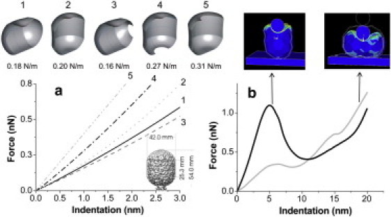
FEA simulation performed on a prohead geometric-like object in upright and laid-down geometries. (a) Simulation on viral shells in different orientations with and without defects. The ϕ29 model (inset) matches the size and shape of the EM model of Morais et al. (37). The standing shells are always stiffest. Even the presence of defects that mimic the connector does not cause the upright shells to soften. (b) When the facetted structure is taken into account, the upright shell is stiffer than the laid-down one during the linear deformation up to 5 nm of indentation.
For the second FEA model we included the icosahedral geometry of the prohead emphasizing the faceting of the viral particles. These simulations were performed using the ANSYS solver (ANSYS, Canonsburg, PA). The model consists of three volumes: the capsid is modeled as a hollow icosahedron with an extra band of hexons around the equator, the tip is modeled as a rigid sphere of diameter 20 nm, and the substrate beneath the capsid is modeled as a flat, rigid surface. Prohead dimension are 2-nm thickness, 40 nm × 54 nm (8) All three elements exhibit planar symmetry, so the model consists of only half the domain. Symmetry boundary conditions, which force the derivatives of the solution at the symmetry plane to zero, ensure that no features of the solution are lost. The capsid was deformed up to 20-nm indentation depth in increments of 0.5 nm. The solution was then mirrored about the symmetry plane to obtain the complete solution. The dimensions of the prohead were taken from cryo-electron microscopy (cryo-EM) (16). The elastic modulus was taken from Ivanovska et al. (8) to be 1.8 GPa.
The model is meshed using ∼12,000 SOLID92 elements, which are 10-node quadratic tetrahedra. Contact between the tip and capsid and between the capsid and substrate is captured using contact pairs with CONTAC174 and TARGE170 elements. These elements are planar and share nodes with the volume mesh at the contact surfaces. We applied symmetry boundary conditions on the areas that are coincident with the symmetry plane and displacement boundary conditions on the tip nodes as well as the substrate nodes. The implementation of contact within the ANSYS solver requires the specification of a friction coefficient. A detailed convergence study of friction coefficients suggested that a value of 0.2 captures buckling phenomena of individual facets of the capsid, which was a desirable component of that model. Also, based on a detailed mesh density convergence study, ∼12,000 elements were used. The model was computed with the parameters in Table 1 and the results are shown in Fig. 4 b.
Table 1.
Parameters of FEA model of Fig. 4b
| Element type | SOLID92 (tet 10-node) |
|---|---|
| Number of elements | 12,832 (top) |
| 11,582 (side) | |
| Young's modulus | 1.8 GPa |
| Poisson's ratio | 0.3 |
| Friction coefficient | 0.20 |
| Contact pair elements | CONTAC174 and TARGE170 |
| Basic options | Auto time stepping: on |
| Number of substeps: 25 | |
| Maximum number of substeps: 100 | |
| Minimum number of substeps: 15 | |
| Nonlinear options | Maximum number of iterations: 500 |
Results
Once the proheads are adsorbed on a modified glass surface (Fig. 1 b), the distribution of heights given by the topographical profiles show two clear peaks at 42 ± 2 and 55 ± 2 nm (inset, Fig. 1 b), which can be ascribed to laid-down-on-the-side (29 proheads) and upright particles (28 proheads), respectively (8). To obtain topographical features of the proteinaceous structure of each isolated prohead with AFM in buffer conditions, is a daunting task which strongly depends on the tip conditions, the stability of the anchorage of the particle to the substrate, and the adsorption geometry. Interestingly, although none of the laid-down particles showed further details beyond some triangular facets (Fig. 1 c), six out of the 28 upright proheads presented definite recognizable details corresponding to the fivefold axial symmetry of the capped-end of proheads adsorbed on the connector (Fig. 1 e).
Figure 1.
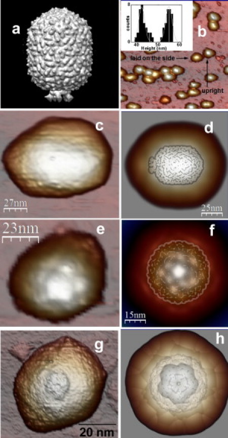
ϕ29 prohead orientation geometry. (a) The EM reconstruction model EMD-1117 (37). (b) AFM image of a typical population of ϕ29 proheads adsorbed on the silanized glass. (Inset) Histogram of heights with two peaks (see text). (c) A typical AFM image of a laid-down-on-the-side prohead. (e and g) AFM images of upright proheads adsorbed by the connector and by the capped-end, respectively. (d, f, and h) Simulated dilation images of the electron microscope data of panel a conveniently oriented to be laid down on the side, adsorbed through the connector, and through the capped-end, respectively. The dilated structures compare fairly well with the corresponding AFM data. The undilated EM data is lightly superimposed on panels d, f, and h.
Likewise, we found just two upright proheads showing the connector facing up. Fig. 1 g presents an example of a prohead absorbed through the capped-end, showing a small hole surrounded by a ring that can be ascribed to the connector. The other unidentified 20 upright proheads do not present enough clues to recognize their adsorption geometry. Therefore they could be either resting on the capped-end or on the connector. For the sake of clarity, we compare the AFM data with the ϕ29 prohead cryo-EM volume (37) (Fig. 1 a). Thus, we calculated the expected geometrical dilation effect between tip and sample by processing the EM data, conveniently oriented, with a dilation algorithm using a 15-nm radius tip (38). The resulting dilated cryo-EM data (Fig. 1, d, f, and h) present topographical features which agree with:
-
1.
The corresponding AFM images of a prohead laid on the side (Fig. 1 c).
-
2.
The fivefold symmetry of the capped-end of a particle adsorbed on the connector (Fig. 1 e).
-
3.
The connector facing upright of a prohead adsorbed on the capped-end (Fig. 1 g), respectively.
As explained in Materials and Methods, we consider only proheads showing a stable mechanical behavior. Typical indentation curves performed on glass (dotted line), on laid-down (shaded), and on upright (solid) ϕ29 proheads are shown in Fig. 2 a. To obtain the prohead stiffness (spring constant) k along the perpendicular direction to the substrate, the recorded nanoindentation curves were fitted linearly (8). The spring constants are sorted depending on the selected prohead adsorption geometry (12) (upright or laid down). In the histogram of Fig. 2 b, we classified the slopes of 56 indentations carried out on five upright (solid) and six laid-down (shaded) proheads. In the upright dataset, two proheads were adsorbed through the connector, two through the capped-end and one unidentified. Gaussian fitting of the data results in spring constants of 0.075 ± 0.020 N/m (average ± SE) and 0.192 ± 0.034 N/m for upright and laid-down proheads, respectively. The spring constant of the laid-down proheads corresponds to the lowest one of the two values reported in Ivanovska et al. (8) within the experimental error.
Figure 2.
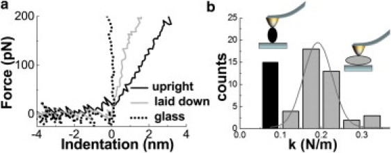
Nanoindentation experiments. (a) The typical forward indentation curves on different locations: glass (dotted), laid-down shell (shaded), and upright shell (solid). (b) Classification of the indentation curve slopes (spring constants) on upright (solid) and laid-down (shaded) proheads.
Laid-down proheads are ∼2.6 times stiffer than upright ones. Interestingly, the spring constant of the upright proheads does not depend on the particle geometry adsorption. Thus the position of the connector, either on top or below the particle, is not relevant for the spring constant within the experimental error. To clarify this, we performed a stiffness map of one of the two upright proheads showing the connector facing up. After performing the usual single FZ experiments to find the prohead spring constant (0.076 ± 0.020 N/m), we succeeded in acquiring a stiffness map (Fig. 3 b) simultaneously with the topographical image (Fig. 3 a). The histogram of the stiffness slopes presented in Fig. 3 c shows two peaks at 0.055 ± 0.007 V/nm and at 0.075 ± 0.005 V/nm that correspond to the prohead and the substrate, respectively.
Figure 3.

Stiffness map of a prohead showing the connector. (a) The topographical AFM data of the connector. (b) The simultaneously acquired stiffness map. The bright colors represent stiff regions and dark colors are soft. (c) The histogram of the stiffness map. The prohead shows as a peak with an average slope of 0.055 V/m. (d) A topographical profile showing the connector (shaded) and the corresponding stiffness profile (dotted).
From these data, the spring constant of the prohead is calculated to be 0.074 ± 0.020 N/m (see Materials and Methods), very close to that obtained with the single FZ experiments. An interesting detail of the stiffness map is the existence of a soft area around the center of the prohead. Fig. 3 d shows two simultaneous profiles of the topography (shaded) and the stiffness map (solid) carried out on this region, providing a direct correlation of the low stiffness area with part of the ring of the connector. Using the values from Fig. 3 d, this suggests a spring constant for the connector of 0.04 N/m, which is almost half than that of the adjacent shell area (∼0.07 N/m).
Discussion
First of all, we discuss the possible influence of the connector on the difference between the spring constants of the upright and laid-down proheads. Just from structural considerations (Fig. 1 a) it seems likely to judge the connector more compliant than the shell. The stiffness map (Fig. 3 d) indeed confirms a reduced spring constant of 0.04 N/m for the connector ring, i.e., half of the value of the vicinal shell. Specifically, the shell just around the connector shows ∼0.07 N/m of stiffness, very close to the 0.075 N/m stiffness of the upright proheads. Single FZ experiments on proheads adsorbed on the capped-end usually do not measure the connector spring constant. This is probably due to the small effective area of the connector compared with the tip diameter. In addition, this area could be even diminished by the damage induced by the tip during the scanning (notice the left part of the ring at Fig. 3 a). In addition, when the prohead is adsorbed on the connector, the measured spring constant is again, within the error, ∼0.075 N/m. Thus, the soft connector is most probably collapsed due to the interaction between its hydrophobic parts (19) and the hydrophobic substrate. Therefore, the shell mainly leans on the rim of the lacking pentamer of the shell.
Indeed, it is not difficult to imagine that proheads that are attached through a nondeformed connector would be so unstable that even obtaining images would be an impossible task. One additional indication is that the mean height of the upright viruses is ∼55 nm (inset, Fig. 1 b), which is the length of the long axis of the shell (Fig. 1 a) skipping the connector. The highest upright viruses show heights of ∼57 nm (Fig. 3 d) and could correspond to proheads adsorbed by the capped-end with the connectors already damaged or deformed during the scanning. Therefore, we conclude that the spring constant of the upright proheads do not depend on the particle geometry adsorption, but the mechanical response is dominated by the shell structure of the prohead.
Having established that the connector does not increase the stiffness of ϕ29, an alternative possibility is that it actually may act as a defect in the prohead structure. In Roos et al. (39), the authors removed pentons from herpes capsids by GuHCl treatment, and report a softening of the viral shell with a factor of 2. Something similar could, in principle, happen in ϕ29 proheads, although the unfeasibility of having prolate prohead shells with the penton included makes the comparison impossible. It also turns out that the mechanical resistance of a given shell strongly depends on the positions of the defects and the direction and magnitude of the deforming force.
To predict the effect of a missing connector on the stiffness of ϕ29, we performed FEA to qualitatively address the stiffness of shells with and without the connector pentamer. In this simulation, a prohead shell-like structure resting on a surface in all the experimentally observed adsorption geometries is indented by a AFM tip with a tip radius of 20 nm (Fig. 4 a). The spring constant of the various geometries is obtained with a linear fit between 0 and 0.3 nN. To simulate the lacking pentamer, a piece of shell with the size of the connector is removed at one of the capped-ends. Comparison of laid-on-the-side model 1 (whole shell) and model 3 (defective shell) shows that the defect provokes the softening of the shell in this adsorption geometry. Interestingly, comparison of upright shell models 2 (whole shell), 4 (defect down), and 5 (defect up) reveals that the defect actually increases the spring constant. This is because the removed curved cap is fairly easy to deform as compared to the cylindrical body of the virus (see also the cartoon of model 2). When this cap is present it is easy to deform and the overall stiffness is reduced. Hence, the fact that the laid-down proheads are stiffer than upright ones cannot be attributed to the absence of the connector pentamer.
Strikingly, when the prohead is considered as a shell, continuum elasticity theory predicts spring constant trends of the empty virus that are completely opposite to our experimental results. The FEA model shows the highest stiffness for the upright shell, whereas the experiments show the highest stiffness for the laid-down shell. This is also confirmed when approaching the geometry analytically, by considering ϕ29 as a shell made by a cylindrical body closed by two spherical caps. By analyzing the elastic response of the cylindrical and spherical part of the virus as independent entities, one would expect that the laid-down virus would be softer than the upright one, because it is easier to deform a cylindrical than a spherical shell of the same radius (40).
The reason is that a cylindrical shell, unlike a spherical one, can be bent without much stretching. In a spherical shell of thickness h and radius R subjected to a concentrated force f, the stretching energy scales as
whereas the bending energy is
where ξ is the deformation, E the Young's modulus, and d the length scale over which the deformation extends. Minimization of the total energy leads to
which implies that the deformation is proportional to the force with an effective spring constant (40)
However, in the indentation of a cylinder (31), the bending energy scales as
and the stretching energy
where now ℓ represents the length along the axis of the cylinder over which the deformation takes place. After minimization of the total energy, one gets that the deformation zone extends over a distance
and that again the force becomes linear in the deformation, but now with a spring constant
Therefore, the ratio of spring constants is
which for the geometry of ϕ29 (R = 21 nm and h = 1.6 nm (16)) becomes approximately
Hence, in the framework of the continuum elasticity theory of shells, the cylindrical body of the virus is expected to be >3 times softer that the spherical caps. This prediction has been confirmed by a second FEA of laid-down indentation on the side and upright viruslike faceted shells with a spherical AFM tip of radius 20 nm (Fig. 4 b) (see Materials and Methods). Note that only the data in the elastic regime before buckling and nonlinear effects are relevant to the discussion in this article.
To tackle this puzzling disagreement between the predictions of continuum elasticity theory and experiments, we should account for an extra effect. It has been shown that, when indenting with an AFM tip on a spherical or cylindrical object whose deformation is controlled by the surface tension, the effective elastic constant is approximately equal to the membrane tension (41).
There are two plausible mechanisms that can originate this tension in the walls of the capsid.
The simplest one is the presence of an internal pressure difference ΔP. One should not forget that double-stranded DNA bacteriophages such as ϕ29 must support at least a pressure of 30–60 atm arising from the DNA packaged inside (7,42,43). Hence, ϕ29 mature heads behave as a nanoscopic pressurized vessel. Laplace's law predicts that a thin cylindrical tank with spherical caps supports a different membrane tension along the axial than along the circumferential direction.
In the spherical caps and along the axial direction of the cylinder, the membrane tension is
whereas in the circumferential (hoop) direction the tension is twice larger, i.e.,
where σx and σθ are the corresponding stresses. Averaging the two principal components of the tension in each zone, one obtains an effective tension which will determine the AFM response. In the cylindrical wall, the average tension is
while for each spherical cap is given by
Therefore, the average tension on the cylindrical wall is expected to be 1.5 times higher than in the caps, which is comparable to the experimental results.
However, inasmuch as the experiments were done with empty viruses, for which the pressure difference is expected to be zero, we have to turn to a second mechanism that could play a similar role to pressure differences and justify the counterintuitive mechanical strength observed in the experiments: the presence of a built-in stress.
Some theoretical works have recently predicted that icosahedral viruses (44) and also geometrically similar nanostructures such as fullerenes and carbon nanotubes (45,46), have a residual stress even at the optimal configuration which minimizes the overall energy. This residual tension arises to compensate the moment of force required to bend a hexagonal sheet into a sphere or cylinder. Thus, an empty capsid can be under tension even in the absence of a pressure difference. The magnitude of this residual stress will depend, among other factors, on the bending stiffness, the radius of the capsid, and the spontaneous curvature (i.e., the preferred curvature that a monolayer of capsid proteins will assume in the absence of any external constraints, which is dictated by the protein-protein interactions).
To achieve more-detailed information about the distribution of stresses in the prolate shell of ϕ29, we performed coarse-grained simulations using a simple model of capsomer-capsomer interactions that has been successful in explaining the structure of spherical (47) and prolated virus (48). In the discrete simulation, the 42 coarse-grained capsomers (i.e., 30 hexamers and 12 pentamers) of ϕ29 are placed on the surface of a spherocylinder made of a cylindrical body of length L closed by two hemispherical caps of radius R. The capsomers interact with an effective Lennard-Jones potential where we have added the bending energy of a spherocylinder,
where κ is the bending stiffness and C0 is the spontaneous curvature. Using Monte Carlo simulations, we have obtained the optimal configuration and analyzed the distribution of local and global lateral stresses following the procedure detailed in Zandi and Reguera (44).
A typical result for the distribution of two-dimensional local lateral stresses is shown in Fig. 5. One can get the average value of the stress in each region (i.e., the spherical caps and the cylindrical body) simply by averaging the local stresses of all capsomers belonging to that region. We have found that the average stress and tension developed on the cylindrical body is consistently higher than that on the spherical caps for a wide region of values of the bending stiffness κ and the spontaneous curvature C0. The ratio of the two averaged tensions oscillates roughly between 1 and 2, depending on the values of κ and C0. Moreover, we have found that the ratio between the cap and cylindrical stresses is independent of the details of the interaction, because it is mainly dictated by the discrete arrangement of capsomers and the curvature of the structure.
Figure 5.
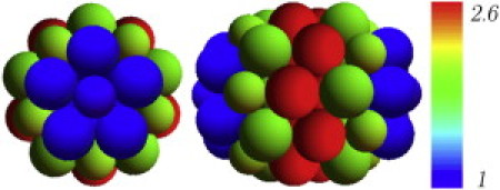
Distribution of local lateral stresses obtained in the simulation of a coarse-grained model of the ϕ29 capsid. The figure shows a top view (left) and a laid-down image (right) of the capsid model. Pentamers and hexamers are represented by spheres with a radius ratio ∼0.8. Colors indicate the relative value of the local lateral stress and the scale is normalized to the smallest value that corresponds to the tip pentamers of the caps.
For small values of the bending stiffness, κ << 1, the results are independent of the spontaneous curvature C0. In that case, we have found that the local stress of the hexamers in the cylindrical body is roughly 2.6 times larger than that one of the pentamers at the apex of the caps (Fig. 5). Moreover, we find that the ratio between the average stresses in the cylindrical body and the spherical caps is roughly 1.5. These results corroborate the trend observed in the experimental findings. Therefore, the combination of intercapsomeric interactions and bending energy associated with a preferred curvature plays a similar role as pressure and generates a built-in lateral stress that is larger in the cylindrical body than in the spherical caps.
To assess the above-mentioned hypothesis, we have performed further experiments using a well-known cross-linking agent such as glutaraldehyde (GAD) (49) (see Materials and Methods). It is commonly used as a fixation agent for cells and biological tissue (50) because it provides the necessary strengthening to the sample to support the manipulations which are inherent for any microscopy. Therefore, it seems evident that the mechanical properties of any protein aggregate will change because the original interprotein bonds are surpassed by the new covalent bond imposed by GAD.
Actually, GAD-induced mechanical reinforcement of macromolecular assemblies has been previously reported by using AFM in microtubuli (51) and cells (52), with both showing a stiffness increase. In the case of the ϕ29 procapsid, GAD acts as staples, which nonspecifically clamp the adjacent proteins of the shell, thus eliminating any preferred curvature or directionality of the interactions and removing, at least partially, any built-in stresses. Indentation experiments were performed on three upright and three laid-down particles cross-linked with GAD (see Materials and Methods); the spring constant distribution is shown in Fig. 6 a. The comparison with GAD free particles (Fig. 6 b) indicates that, after the addition of 0.25% of glutaraldehyde, the built-in stress has been partially suppressed and upright shells are reinforced in such way that they become stiffer than laid-down ones as predicted by continuum elasticity.
Figure 6.
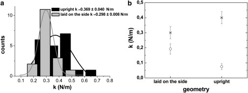
Glutaraldehyde-induced mechanical reinforcement of proheads. (a) The spring constant distribution of glutaraldehyde-treated proheads: laid down on the side (shaded) and upright (solid). (b) The spring constant of the proheads with (cross) and without (circle) glutaraldehyde.
Conclusions
Our results reveal the strikingly anisotropic mechanical properties of ϕ29 bacteriophage prohead virus particles that can be explained by the presence of prestress in the capsid. The presence of these residual stresses might play an important biophysical role for the viability of the virus. Induced prestress is commonly applied not only in material science, but also in many biological tissues (although it has not been shown for molecular aggregates so far) to increase their mechanical resistance and help them to better tolerate tension (53).
The presence of prestress may stiffen the capsid to prevent any damage from mechanical assaults such as osmotic shocks or DNA packing, providing protection to the viral genome during the extracellular virus cycle. On the other hand, the presence of this residual stress could play a significant role in the pressure-assisted DNA translocation (ejection) through the tail into the host (17) performed by the mature head. A simple estimation using the Laplace law indicates that the measured stress of the equatorial zone is equivalent to a pressure difference of
the same order of magnitude as that exerted by the confined DNA (7,42,43). Therefore, the built-in stress could confine the internal pressure along the long axis of the prolated shell, helping us to make the most of the stored elastic energy to initiate the DNA translocation process through the tail.
Another interesting biophysical question relates to how this prestress is generated during the capsid formation. In the assembly process, there is a competition between the tendency of proteins to aggregate at the preferred curvature and the need to minimize the rim area exposed in a partially assembled capsid by making a closed structure (54). If the curvature of the closed capsid is different from the spontaneous one (i.e., the preferred curvature at which capsid proteins will assemble without forcing them to make a closed structure), lateral stress will develop. Indeed not only ϕ29, but most complex double-stranded DNA bacteriophages, require a scaffolding protein which coassembles with the main head protein to produce a prohead with the correct shape and size (55). ϕ29 proheads do not assemble properly without the scaffolding protein (24).
This directing role of the scaffold is transient. Once the shell is built, the scaffolding is released concomitant to the DNA packing in the shell. We cannot exclude the possibility that a certain amount of scaffolding protein might be released from proheads during storage, but this is not followed by any apparent change in the structure of the proheads. Because protein-binding interactions are on the order of a few kBT (56), it is likely that scaffolding proteins might help to impose a curvature in the capsid significantly different from the spontaneous one, by assisting the bending of the proteins at the junctions. This will generate a much larger shell stress, which will reinforce the strength of the capsid. In the absence of the scaffolding, the stress generated during the assembly might help to better tolerate the packaging, avoiding a significant expansion.
Acknowledgments
P.J.d.P. was funded by projects No. MAT2008-02533 (Ministerio de Ciencia e Innovacion (MICINN)), No. P2009/MAT-1467 (Comunidad Autónoma de Madrid (CAM)), and No. PIB2010US-00233 (MICINN). D.R. and A.L. were funded by grant No. FIS2008-04386 and the I3P and FI program of the Generalitat of Catalonia and the European Social Fund. J.L.C. was funded by grant No. S2009/MAT-1507 from the CAM, Consolider No. CSD2007-00010 from the Ministerio de Ciencia y Innovacion (MCI), and BFU No. 2008-02328/BMC from the MCI (MICINN). P.A.S. was funded by project No. FIS2009-13403-C02 (MICINN) and No. P2009/MAT-1467 (CAM). I.A.T.S. was supported by the Deutsche Forschungsgemeinschaft Research Center for Molecular Physiology of the Brain/Excellence Cluster 171.
References
- 1.Flint S.J., Enquist L.W., Skalka A.M. ASM Press; Washington DC: 2004. Principles of Virology. [Google Scholar]
- 2.Moody M.F. Geometry of phage head construction. J. Mol. Biol. 1999;293:401–433. doi: 10.1006/jmbi.1999.3011. [DOI] [PubMed] [Google Scholar]
- 3.Prigent M., Leroy M., DuBow M.S. A diversity of bacteriophage forms and genomes can be isolated from the surface sands of the Sahara Desert. Extremophiles. 2005;9:289–296. doi: 10.1007/s00792-005-0444-5. [DOI] [PubMed] [Google Scholar]
- 4.Cordova A., Deserno M., Ben-Shaul A. Osmotic shock and the strength of viral capsids. Biophys. J. 2003;85:70–74. doi: 10.1016/S0006-3495(03)74455-5. [DOI] [PMC free article] [PubMed] [Google Scholar]
- 5.Kindt J., Tzlil S., Gelbart W.M. DNA packaging and ejection forces in bacteriophage. Proc. Natl. Acad. Sci. USA. 2001;98:13671–13674. doi: 10.1073/pnas.241486298. [DOI] [PMC free article] [PubMed] [Google Scholar]
- 6.Purohit P.K., Inamdar M.M., Phillips R. Forces during bacteriophage DNA packaging and ejection. Biophys. J. 2005;88:851–866. doi: 10.1529/biophysj.104.047134. [DOI] [PMC free article] [PubMed] [Google Scholar]
- 7.Evilevitch A., Lavelle L., Gelbart W.M. Osmotic pressure inhibition of DNA ejection from phage. Proc. Natl. Acad. Sci. USA. 2003;100:9292–9295. doi: 10.1073/pnas.1233721100. [DOI] [PMC free article] [PubMed] [Google Scholar]
- 8.Ivanovska I.L., de Pablo P.J., Wuite G.J. Bacteriophage capsids: tough nanoshells with complex elastic properties. Proc. Natl. Acad. Sci. USA. 2004;101:7600–7605. doi: 10.1073/pnas.0308198101. [DOI] [PMC free article] [PubMed] [Google Scholar]
- 9.Roos W.H., Bruinsma R., Wuite G.J.L. Physical virology. Nat. Phys. 2010;6:733–743. [Google Scholar]
- 10.Ivanovska I., Wuite G., Evilevitch A. Internal DNA pressure modifies stability of WT phage. Proc. Natl. Acad. Sci. USA. 2007;104:9603–9608. doi: 10.1073/pnas.0703166104. [DOI] [PMC free article] [PubMed] [Google Scholar]
- 11.Michel J.P., Ivanovska I.L., Schmidt C.F. Nanoindentation studies of full and empty viral capsids and the effects of capsid protein mutations on elasticity and strength. Proc. Natl. Acad. Sci. USA. 2006;103:6184–6189. doi: 10.1073/pnas.0601744103. [DOI] [PMC free article] [PubMed] [Google Scholar]
- 12.Carrasco C., Carreira A., de Pablo P.J. DNA-mediated anisotropic mechanical reinforcement of a virus. Proc. Natl. Acad. Sci. USA. 2006;103:13706–13711. doi: 10.1073/pnas.0601881103. [DOI] [PMC free article] [PubMed] [Google Scholar]
- 13.Carrasco C., Castellanos M., Mateu M.G. Manipulation of the mechanical properties of a virus by protein engineering. Proc. Natl. Acad. Sci. USA. 2008;105:4150–4155. doi: 10.1073/pnas.0708017105. [DOI] [PMC free article] [PubMed] [Google Scholar]
- 14.Kol N., Gladnikoff M., Rousso I. Mechanical properties of murine leukemia virus particles: effect of maturation. Biophys. J. 2006;91:767–774. doi: 10.1529/biophysj.105.079657. [DOI] [PMC free article] [PubMed] [Google Scholar]
- 15.Kol N., Shi Y., Rousso I. A stiffness switch in human immunodeficiency virus. Biophys. J. 2007;92:1777–1783. doi: 10.1529/biophysj.106.093914. [DOI] [PMC free article] [PubMed] [Google Scholar]
- 16.Tao Y.Z., Olson N.H., Baker T.S. Assembly of a tailed bacterial virus and its genome release studied in three dimensions. Cell. 1998;95:431–437. doi: 10.1016/s0092-8674(00)81773-0. [DOI] [PMC free article] [PubMed] [Google Scholar]
- 17.González-Huici V., Salas M., Hermoso J.M. The push-pull mechanism of bacteriophage ϕ29 DNA injection. Mol. Microbiol. 2004;52:529–540. doi: 10.1111/j.1365-2958.2004.03993.x. [DOI] [PubMed] [Google Scholar]
- 18.Chemla Y.R., Aathavan K., Bustamante C. Mechanism of force generation of a viral DNA packaging motor. Cell. 2005;122:683–692. doi: 10.1016/j.cell.2005.06.024. [DOI] [PubMed] [Google Scholar]
- 19.Guasch A., Pous J., Coll M. Detailed architecture of a DNA translocating machine: the high-resolution structure of the bacteriophage ϕ29 connector particle. J. Mol. Biol. 2002;315:663–676. doi: 10.1006/jmbi.2001.5278. [DOI] [PubMed] [Google Scholar]
- 20.Valpuesta J.M., Carrascosa J.L. Structure of viral connectors and their function in bacteriophage assembly and DNA packaging. Q. Rev. Biophys. 1994;27:107–155. doi: 10.1017/s0033583500004510. [DOI] [PubMed] [Google Scholar]
- 21.Wikoff W.R., Johnson J.E. Virus assembly: imaging a molecular machine. Curr. Biol. 1999;9:R296–R300. doi: 10.1016/s0960-9822(99)80183-3. [DOI] [PubMed] [Google Scholar]
- 22.Ibarra B., Castón J.R., Carrascosa J.L. Topology of the components of the DNA packaging machinery in the phage ϕ29 prohead. J. Mol. Biol. 2000;298:807–815. doi: 10.1006/jmbi.2000.3712. [DOI] [PubMed] [Google Scholar]
- 23.Camacho A., Jiménez F., Salas M. Assembly of Bacillus subtilis phage ϕ29. 1. Mutants in the cistrons coding for the structural proteins. Eur. J. Biochem. 1977;73:39–55. doi: 10.1111/j.1432-1033.1977.tb11290.x. [DOI] [PubMed] [Google Scholar]
- 24.Choi K.H., Morais M.C., Rossmann M.G. Determinants of bacteriophage ϕ29 head morphology. Structure. 2006;14:1723–1727. doi: 10.1016/j.str.2006.09.007. [DOI] [PubMed] [Google Scholar]
- 25.Guo P.X., Erickson S., Anderson D. Regulation of the phage ϕ29 prohead shape and size by the portal vertex. Virology. 1991;183:366–373. doi: 10.1016/0042-6822(91)90149-6. [DOI] [PMC free article] [PubMed] [Google Scholar]
- 26.Morais M.C., Kanamaru S., Rossmann M.G. Bacteriophage ϕ29 scaffolding protein gp7 before and after prohead assembly. Nat. Struct. Biol. 2003;10:572–576. doi: 10.1038/nsb939. [DOI] [PubMed] [Google Scholar]
- 27.Xiang Y., Morais M.C., Rossmann M.G. Structural changes of bacteriophage ϕ29 upon DNA packaging and release. EMBO J. 2006;25:5229–5239. doi: 10.1038/sj.emboj.7601386. [DOI] [PMC free article] [PubMed] [Google Scholar]
- 28.Moreno-Herrero F., de Pablo P.J., Baro A.M. Jumping mode scanning force microscopy: a suitable technique for imaging DNA in liquids. Appl. Surf. Sci. 2003;210:22–26. [Google Scholar]
- 29.Sader J.E., Chon J.W.M., Mulvaney P. Calibration of rectangular atomic force microscope cantilevers. Rev. Sci. Instrum. 1999;70:3967–3969. [Google Scholar]
- 30.de Pablo P.J., Gomez-Navarro C., Baro A.M. Performing current versus voltage measurements of single-walled carbon nanotubes using scanning force microscopy. Appl. Phys. Lett. 2002;80:1462–1464. [Google Scholar]
- 31.de Pablo P.J., Schaap I.A.T., Schmidt C.F. Deformation and collapse of microtubules on the nanometer scale. Phys. Rev. Lett. 2003;91:098101. doi: 10.1103/PhysRevLett.91.098101. [DOI] [PubMed] [Google Scholar]
- 32.Klug W.S., Bruinsma R.F., Wuite G.J. Failure of viral shells. Phys. Rev. Lett. 2006;97:228101. doi: 10.1103/PhysRevLett.97.228101. [DOI] [PubMed] [Google Scholar]
- 33.Vliegenthart G.A., Gompper G. Mechanical deformation of spherical viruses with icosahedral symmetry. Biophys. J. 2006;91:834–841. doi: 10.1529/biophysj.106.081422. [DOI] [PMC free article] [PubMed] [Google Scholar]
- 34.Zink M., Grubmüller H. Mechanical properties of the icosahedral shell of southern bean mosaic virus: a molecular dynamics study. Biophys. J. 2009;96:1350–1363. doi: 10.1016/j.bpj.2008.11.028. [DOI] [PMC free article] [PubMed] [Google Scholar]
- 35.A-Hassan E., Heinz W.F., Hoh J.H. Relative microelastic mapping of living cells by atomic force microscopy. Biophys. J. 1998;74:1564–1578. doi: 10.1016/S0006-3495(98)77868-3. [DOI] [PMC free article] [PubMed] [Google Scholar]
- 36.Schaap I.A.T., Carrasco C., Schmidt C.F. Elastic response, buckling, and instability of microtubules under radial indentation. Biophys. J. 2006;91:1521–1531. doi: 10.1529/biophysj.105.077826. [DOI] [PMC free article] [PubMed] [Google Scholar]
- 37.Morais M.C., Choi K.H., Rossmann M.G. Conservation of the capsid structure in tailed dsDNA bacteriophages: the pseudoatomic structure of ϕ29. Mol. Cell. 2005;18:149–159. doi: 10.1016/j.molcel.2005.03.013. [DOI] [PubMed] [Google Scholar]
- 38.Horcas I., Fernández R., Baro A.M. WSXM: a software for scanning probe microscopy and a tool for nanotechnology. Rev. Sci. Instrum. 2007;78:013705. doi: 10.1063/1.2432410. [DOI] [PubMed] [Google Scholar]
- 39.Roos W.H., Radtke K., Wuite G.J. Scaffold expulsion and genome packaging trigger stabilization of herpes simplex virus capsids. Proc. Natl. Acad. Sci. USA. 2009;106:9673–9678. doi: 10.1073/pnas.0901514106. [DOI] [PMC free article] [PubMed] [Google Scholar]
- 40.Landau L.D., Lifshizt E. Pergamon; London, UK: 1986. Theory of Elasticity. [Google Scholar]
- 41.Arnoldi M., Fritz M., Boulbitch A. Bacterial turgor pressure can be measured by atomic force microscopy. Phys. Rev. E Stat. Phys. Plasmas Fluids Relat. Interdiscip. Topics. 2000;62(1 Pt B):1034–1044. doi: 10.1103/physreve.62.1034. [DOI] [PubMed] [Google Scholar]
- 42.Smith D.E., Tans S.J., Bustamante C. The bacteriophage straight ϕ29 portal motor can package DNA against a large internal force. Nature. 2001;413:748–752. doi: 10.1038/35099581. [DOI] [PubMed] [Google Scholar]
- 43.Köster S., Evilevitch A., Weitz D.A. Influence of internal capsid pressure on viral infection by phage λ. Biophys. J. 2009;97:1525–1529. doi: 10.1016/j.bpj.2009.07.007. [DOI] [PMC free article] [PubMed] [Google Scholar]
- 44.Zandi R., Reguera D. Mechanical properties of viral capsids. Phys. Rev. E Stat. Nonlin. Soft Matter Phys. 2005;72:021917. doi: 10.1103/PhysRevE.72.021917. [DOI] [PubMed] [Google Scholar]
- 45.Robertson D.H., Brenner D.W., Mintmire J.W. Energetics of nanoscale graphitic tubules. Phys. Rev. B Condens. Matter. 1992;45:12592–12595. doi: 10.1103/physrevb.45.12592. [DOI] [PubMed] [Google Scholar]
- 46.Chandra N., Namilae S., Shet C. Local elastic properties of carbon nanotubes in the presence of Stone-Wales defects. Phys. Rev. B. 2004;69:094101. [Google Scholar]
- 47.Zandi R., Reguera D., Rudnick J. Origin of icosahedral symmetry in viruses. Proc. Natl. Acad. Sci. USA. 2004;101:15556–15560. doi: 10.1073/pnas.0405844101. [DOI] [PMC free article] [PubMed] [Google Scholar]
- 48.Luque A., Zandi R., Reguera D. Optimal architectures of elongated viruses. Proc. Natl. Acad. Sci. USA. 2010;107:5323–5328. doi: 10.1073/pnas.0915122107. [DOI] [PMC free article] [PubMed] [Google Scholar]
- 49.Kiernan J.A. Formaldehyde, formalin, paraformaldehyde and glutaraldehyde: what they are and what they do. Microsc.Today. 2000;8:1–3. [Google Scholar]
- 50.Alberts B., Lewis J., Walter P. Garland; New York: 2002. Molecular Biology of the Cell. [Google Scholar]
- 51.Vinckier A., Heyvaert I., Hellemans L. Immobilizing and imaging microtubules by atomic force microscopy. Ultramicroscopy. 1995;57:337–343. doi: 10.1016/0304-3991(94)00194-r. [DOI] [PubMed] [Google Scholar]
- 52.Hutter J.L., Chen J., Chan B.M. Atomic force microscopy investigation of the dependence of cellular elastic moduli on glutaraldehyde fixation. J. Microsc. (Oxford) 2005;219:61–68. doi: 10.1111/j.1365-2818.2005.01497.x. [DOI] [PubMed] [Google Scholar]
- 53.Storm C., Pastore J.J., Janmey P.A. Nonlinear elasticity in biological gels. Nature. 2005;435:191–194. doi: 10.1038/nature03521. [DOI] [PubMed] [Google Scholar]
- 54.Zandi R., van der Schoot P., Reiss H. Classical nucleation theory of virus capsids. Biophys. J. 2006;90:1939–1948. doi: 10.1529/biophysj.105.072975. [DOI] [PMC free article] [PubMed] [Google Scholar]
- 55.Dokland T. Scaffolding proteins and their role in viral assembly. Cell. Mol. Life Sci. 1999;56:580–603. doi: 10.1007/s000180050455. [DOI] [PMC free article] [PubMed] [Google Scholar]
- 56.Zlotnick A. Are weak protein-protein interactions the general rule in capsid assembly? Virology. 2003;315:269–274. doi: 10.1016/s0042-6822(03)00586-5. [DOI] [PubMed] [Google Scholar]