Abstract
In conventional computers, wiring between transistors is required to enable the execution of Boolean logic functions. This has resulted in processors in which billions of transistors are physically interconnected, which limits integration densities, gives rise to huge power consumption and restricts processing speeds. A method to eliminate wiring amongst transistors by condensing Boolean logic into a single active element is thus highly desirable. Here, we demonstrate a novel logic architecture using only a single electromechanical parametric resonator into which multiple channels of binary information are encoded as mechanical oscillations at different frequencies. The parametric resonator can mix these channels, resulting in new mechanical oscillation states that enable the construction of AND, OR and XOR logic gates as well as multibit logic circuits. Moreover, the mechanical logic gates and circuits can be executed simultaneously, giving rise to the prospect of a parallel logic processor in just a single mechanical resonator.
 Eliminating wiring in transistors could lead to high integration densities and low power consumption. Here, multiple logic gates are implemented in a microelectromechanical resonator by parametrically mixing binary information channels corresponding to mechanical oscillations of the resonator at different frequencies.
The concept of encoding multiple signals with different frequencies was originally pioneered in optical fibre networks to increase their capacity1,2,3. To achieve this, wavelength division multiplexing (WDM) was developed, which enables a single optical fibre to operate as if it were a bundle of fibres. State-of-the-art WDM can enable more than a 1,000 different wavelengths of light to propagate in parallel through a single fibre, yielding a dramatic increase in signal throughput in an optical fibre network. Conceptually, WDM can be regarded as not addressing real space, that is, the choice of a particular optical fibre, but rather as addressing frequency space, that is, the choice of wavelength in a given optical fibre.
On the basis of this principle, here, we demonstrate the Boolean logic analogue4 where binary information is not encoded in physically distinct devices, but is instead encoded as different oscillation frequencies in a single device—the increasingly common electromechanical resonator5,6. This novel approach allows a single device to not only operate as if it were a fully integrated logic circuit but also to operate as a parallel logic processor enabling the simultaneous execution of multiple Boolean functions where crucially all interconnects have been eliminated.
Results
Device
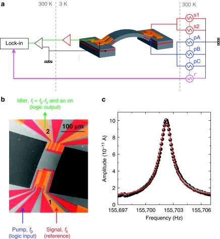
The GaAs/AlGaAs-based mechanical resonator used in this study is shown and described in Figures 1a and 1b, and has a fundamental mode at f0=ω0/2π=155,702 Hz with a quality factor Q=140,000 (Fig. 1c and Methods)7. The piezoelectric effect in the GaAs/AlGaAs heterostructure can enable electrical actuation and detection of mechanical motion as well as the parametric amplification via force constant modulation8,9,10.
Figure 1. The electromechanical parametric resonator.
(a) A schematic of the experimental setup where the mechanical resonator is in the geometry of a doubly clamped beam (grey) with a length, width and thickness of 260, 84, and 1.35 μm, respectively, and it hosts an out-of-plane oscillation mode. The mechanical oscillator has Schottky Au-electrodes (orange) located above both clamping points, below which a 2DEG is located (red). Application of a.c. bias to either the 2DEG or the Au-electrodes can trigger both harmonic and parametric resonances where the mechanical motion is monitored by detecting in either a lock-in amplifier or a spectrum analyser the motion-induced piezovoltage, which is amplified by an on-chip amplifier (red triangle) and a room temperature transimpedance amplifier (black triangle). In all cases, the signals s1 and s2 are applied to the large Au-electrode with a 50 μVrms actuation amplitude and the pumps pA, pB and pC are applied to the 2DEG with 40 mVrms actuation amplitude where the reference r is used for the lock-in measurements. (b) A false-colour scanning electron microscopic image of the electromechanical resonator where the pump (logic input), signal excitation (to functionalize logic operations) and the idler (logic output) are marked. (c) The electromechanical resonance (dots) measured via the lock-in amplifier and fitted with a harmonic oscillator response (line).
Among the 12 independent electrical contacts, a single two-dimensional electron gas (2DEG) contact is used for binary information input with a frequency around 2f0, and the gate located directly above (gate 1) is used for injecting an excitation around f0. Henceforth, these excitations are termed pump and signal, respectively, in analogy with frequency conversion in optical parametric amplifiers11. The signal can directly excite a mechanical oscillation and is necessary for functionalizing logic operations. In contrast, the pump cannot directly excite mechanical motion as its amplitude is below the parametric resonance threshold7. However, the interaction between signal and pump results in the excitation of mechanical motion as shown below. Within the resonance bandwidth, multiple oscillations at different frequencies can be simultaneously excited by injecting multiple pumps with slightly different frequencies. In all cases, the motion was electrically detected via gate 2, that is, this gate is used for the readout of Boolean functions as shown in Figure 1b.
Mechanical idler generation
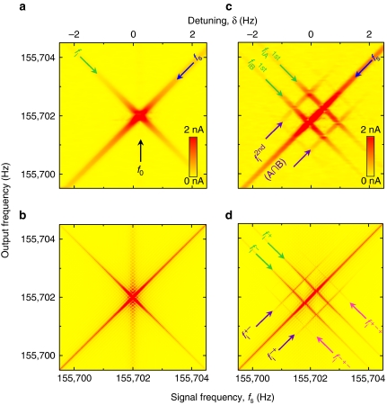
Parametric frequency conversion has an essential role in the execution of logic functions in this architecture and its operation is first described here12,13. A pump with fixed frequency, fp=2f0, is injected into the 2DEG, while a signal at frequency fs=f0+δ, where δ is a variable, is applied to gate 1. The frequency response measured via gate 2 is shown in Figure 2a as a function of fs and the corresponding theoretical response is shown in Figure 2b (Methods). In addition to the input signal (blue arrow), an additional oscillation with a negative slope (green arrow) is observed. This excitation arises because of mixing between fp and fs resulting in the creation of an idler at fi=fp−fs=f0−δ, thus demonstrating mechanical parametric frequency conversion for the first time (Supplementary Note 1 and Supplementary Figure S1).
Figure 2. The mechanical idler dynamics.
(a) The response of the mechanical oscillator measured via the lock-in amplifier with fp=2f0+Δ where Δ=0 Hz and fs=f0+δ reveals the fundamental mode fs and the idler fi=f0−δ. (b) The corresponding theoretical response generated from equation (9) (Methods). (c) The response of the mechanical oscillator measured via the lock-in amplifier, with fpA=2f0+Δ and fpB=2f0−Δ where Δ=0.5 Hz, and fs=f0+δ reveals, in addition to fs, the two first-order idlers  and
and  and two second-order idlers
  that can be used to implement mechanical logic gates. (d) The corresponding numerical simulation except equation (9) is modified to include two pumps, and all the higher order idlers are labelled (Methods). In all cases, the experimental response is broader than the numerical simulations because of an experimental resolution band width (RBW) of 50 mHz.
Logic gates
To demonstrate the AND (∩) operation, two pump excitations with frequency fpA=2f0+Δ and fpB=2f0−Δ with fixed detuning Δ are injected into the 2DEG, which correspond to binary inputs A and B, respectively, where the absence (presence) of the pump yields the binary input 0 (1). The frequency response measured via gate 2 and shown in Figure 2c (along with the corresponding theoretical response in Fig. 2d) now reveals not only the above first-order idlers fiA=f0+Δ−δ and fiB=f0−Δ−δ (green arrows) corresponding to the two pumps but also two second-order idlers (purple arrows). The second-order idlers arise because of mixing between the first-order idlers fiA and fiB, and the two pumps fpA and fpB, resulting in fpA−fiB=f0+2Δ+δ and fpB−fiA=f0−2Δ+δ (Methods). It should be emphasized that the second-order idlers can only be created when the two pumps pA and pB are active, thus enabling the execution of the A∩B logic gate where the absence (presence) of the idlers corresponds to the binary output 0 (1).
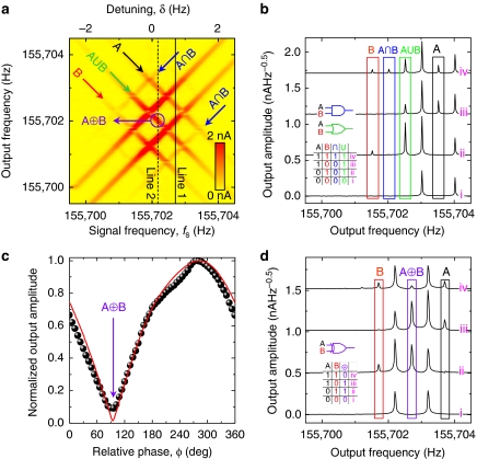
Next, to demonstrate the OR (∪) operation, the mechanical resonator is injected with two signals at fs1=f0+Δ+δ and fs2=f0−Δ+δ, which results in the reference vibrations being excited by both s1 and s2 (Supplementary Note 2 and Supplementary Figure S2). The complete set of idlers created when all the signals and pumps are activated is shown in Figure 3a. Activating only fpA yields two first-order idlers f0−δ (green arrow) and f0−δ+2Δ (black arrow A). Activating only fpB yields f0−δ−2Δ (red arrow B) and f0−δ (green arrow). From these measurements, it is seen that the f0−δ idler can be excited by either pump A or pump B, which enables the realization of the A∪B gate. The mechanical frequency response obtained at a fixed signal frequency (along line 1 in Fig. 3a) as a function of pump excitation is shown in Figure 3b and it clearly demonstrates the AND and OR operation. It should be emphasized that the two logic outputs can be obtained in parallel with only a single device in contrast to conventional logic devices where only sequential operation is available.
Figure 3. Mechanical logic gates.
(a) The mechanical resonator's response measured via the lock-in amplifier with two signal excitations at fs1=f0+Δ+δ and fs2=f0−Δ+δ and two pump excitations at fpA=2f0+Δ and fpB=2f0−Δ where Δ=0.5 Hz. Using this response, an ∩ gate can be realized by any second-order idler (blue arrows), the ∪ gate can be realized via the degenerate first-order idler (green arrow) and the ⊕ gate can be realized via the degenerate idler at exactly fr=f0 (purple circle). (b) Two-bit binary input channels A and B can be encoded via fpA and fpB where the ∩ and ∪ logic gates can be realized by measuring the response of the mechanical resonator along the line 1 in a as a function of pump A and B, while both signal excitations are active. The resulting response measured via a spectrum analyser with a RBW of 25 mHz reveals both ∩ and ∪ gates in parallel in a single mechanical resonator. (c) The ⊕ gate can also be realized via the degenerate idler at exactly fr=f0 (purple circle in a) by varying the phase difference between s1 and s2, which can lead to both constructive and destructive interference. The destructive interference can be used to realize a ⊕ logic gate when φ=94° where the dots are from the experimental measurement and the line is the result of a numerical simulation (Methods). (d) The ⊕ gate is demonstrated along line 2 in a at fr=f0 by measuring the response of the mechanical resonator in a spectrum analyser with RBW=25 mHz as a function of pA and pB when the phase difference between s1 and s2 is 94° with an on/off ratio of 10:1. All the spectra are offset for clarity and are numbered (roman numerals) to correlate with the numbered truth combinations in their corresponding truth tables where the various inputs and gates have been colour coded.
To implement the XOR (⊕) gate, we exploit the interference between the two idlers along f0−δ by simply adjusting the relative phase φ between s1 and s2. At an appropriate value of φ, the f0−δ idler can be completely cancelled at fs=f0 when both pumps A and B are active as shown in Figure 3c, which enables the realization of the A⊕B gate as a function of pump excitation (along line 2 in Fig. 3a) as shown in Figure 3d. The realization of a universal electromechanical logic gate in a single device with AND, OR and XOR functions can enable the construction of any other logic gate.
Logic circuits
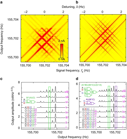
Beyond the implementation of fundamental two-bit logic gates, we also investigate the prospect of multibit logic circuits in a single mechanical resonator. To do this, a third pump is injected into the system at fpC=2f0+2Δ, which is used to encode a third-bit labelled as C. The resulting response of the system measured as above via gate 2 as a function of fs is shown in Figure 4a along with the corresponding theoretical response in Figure 4b (Methods).
Figure 4. Multibit mechanical logic circuits.
(a) The response of the mechanical resonator measured via the lock-in amplifier with two signal excitations at fs1=f0+Δ+δ and fs2=f0−Δ+δ and three pumps fpA=2f0+Δ, fpB=2f0−Δ and fpC=2f0+2Δ where Δ=0.5 Hz. (b) The corresponding numerical simulation except equation (9) is modified to include three pumps and two signals (Methods). (c) The 3-bit B∩(A∪C) logic circuit is constructed with the two second-order idlers fpB−(fpA−fs) and fpB−(fpC−fs) where Δs1=Δs2=0.5 Hz, ΔpA=0.25 Hz, ΔpB=−0.25 Hz and ΔpC=0.75 Hz. (d) The A∪(B∩C) and (A∩B)∪(B∩C)∪(C∩A) logic circuits are constructed in parallel from first and second-order idlers fpA=fs, fpB−(fpC−fs) and three second-order idlers fpA−(fpB−fs), fpB−(fpC−fs) and fpC−(fpA−fs), respectively, with Δs1=0.5 Hz, Δs2=−1 Hz, ΔpA=0.25 Hz, ΔpB=−0.25 Hz and ΔpC=0.75 Hz. In both cases, the mechanical parametric resonator was sampled via a spectrum analyser with an RBW=12.5 mHz. All the spectra are offset for clarity and are numbered (roman numerals) to correlate with the numbered truth combinations in their corresponding truth tables where the various inputs and circuits have been colour coded.
To demonstrate a multibit logic circuit, we implement the sequence B∩(A∪C), where A, B and C are the binary input channels at fpA, fpB and fpC, respectively. This logic circuit can be decomposed as B∩A and B∪C, which can be mathematically represented by two second-order idlers fpB−(fpA−fs) and fpB−(fpC−fs), where fs is either due to s1 or s2. To achieve maximum fidelity for this logic circuit, the idlers must only intersect with each other and their visibility will be maximized at f0. Rewriting the signal and pump excitations as fs1=f0+Δs1, fs2=f0+Δs2, fpA=2f0+ΔpA, fpB=2f0+ΔpB and fpC=2f0+ΔpC can enable these boundary conditions to be expressed as 0=ΔpB−ΔpA+Δs(1 or 2) and 0=ΔpB−ΔpC+Δs(1 or 2), where ΔpA≠ΔpB≠ΔpC. From these expressions, the detunings for the signal and pump excitations that lead to 100% fidelity for the B∩(A∪C) logic circuit can be extracted, and the resulting circuit is executed in Figure 4c.
Using a similar analytical approach, various 3-bit logic circuits can be constructed in parallel including (A∩B)∪(B∩C)∪(C∩A), that is, the majority gate which is shown in Figure 4d (Supplementary Figure S3 for additional circuits). All logic operations including multibit logic circuits can be reproduced by numerical simulations, thus enabling more advanced logic circuits to be easily designed (Methods). A generalized formulism to implement multibit logic circuits for arbitrary Boolean functions will be reported elsewhere.
Discussion
The first programmable computer was pioneered in a mechanical architecture almost two centuries ago14. However, mechanical computation was rendered obsolete with the advent of the transistor15, which gave rise to an electrical binary-unit (bit) for Boolean logic4. With the recent emergence of electromechanical resonators5,6, the concept of a mechanical computer has been revived as this offers the tantalizing prospect of low power consumption16. In spite of some recent experimental effort, a universal electromechanical logic gate based on Boolean algebra has remained beyond reach7,17,18,19,20.
The parametric frequency conversion demonstrated here not only permits the realization of all the primary logic gates in an electromechanical resonator for the first time16,18,19,20,21 but it also enables multibit logic circuits to be executed in a single mechanical resonator as well as providing an architecture in which parallel logic circuits can be easily constructed. Consequently, a mechanical computer based on these concepts offers the prospect of unrivalled integration density, low power consumption7,16 and potentially high speed, as information does not have to be passed between multiple transistors as in conventional sequential logic circuits. Moreover, this concept contributes significantly to the beyond transistor-based computation debate22.
To translate this proof-of-principle prototype into a more practical device, both room temperature and atmospheric operation is a necessary prerequisite. Although the present device can operate at room temperature23, the viscous damping present at atmospheric pressure degrades its performance. The effects of viscous damping could be reduced by utilizing on-chip vacuum packaging24 or by employing nanomechanical resonators25. The use of nanomechanical resonators would also result in higher operation frequencies and integration densities, for example, a 1 GHz mechanical beam oscillator could be realized with a length and width of 1 μm and 100 nm, respectively, leading to integration densities as high as 108 oscillators per cm2 (ref. 7). The outstanding obstacle in the realization of the above mechanical computer is a 1 GHz piezoelectric nanomechanical resonator with Q sufficiently high to yield good signal-to-noise ratios and the ability to host the parametric amplification functionality. A potential path to these requirements might be found via piezoelectric bulk acoustic wave resonators26.
Whereas the performance of the current device is typically Δ∼1 Hz per logic operation, it is instructive to estimate the prospects of this technology, for example, with a 1 GHz resonator with Q=100, yielding an operation bandwidth of 10 MHz (ref. 27). Using a state-of-the-art computer word size of 64 bits with 64 parallel processes would result in 5×10⁶ 64-bits logic operations per second with only a single nanomechanical device. If such nanomechanical processors were assembled on to a chip with the above described integration density, it could result in data-processing capacity of 1014 Hz cm−2. Even higher processing capacity would be available in graphene membrane resonators with dimensions of a few nanometers, in which resonance frequencies as high as 400 GHz could be achieved28. A nanomechanical computer realized in this mould would yield unprecedented data-processing power making it a highly tantalizing prospect, which merits further investigation.
Methods
Experimental
The electromechanical resonator was fabricated via conventional micromachining processes from a GaAs/AlGaAs modulation-doped heterostructure sustaining a 2DEG 90 nm below the surface. The sample was mounted in a high vacuum insert (8×10⁻⁸ mbar), which was then placed in a 4He cryostat at 3 K. The mechanical response was measured using standard low-frequency lock-in and amplification techniques.
The signal, pump and reference (for the lock-in measurements) excitations were generated via six signal generators (NF Wavefactory 1974), which were coupled and synchronized via their internal 10 MHz reference clock. The electromechanical oscillator's response was amplified by an on-chip Si-nanofield-effect transistor with 30 dB gain, followed by a transimpedance amplifier (Femto DLPCA-200) with a gain of 107 VA−1 and measured in either a lock-in amplifier (Ametek 7265) or a spectrum analyser (Agilent 89410A).
Multiple idler generation
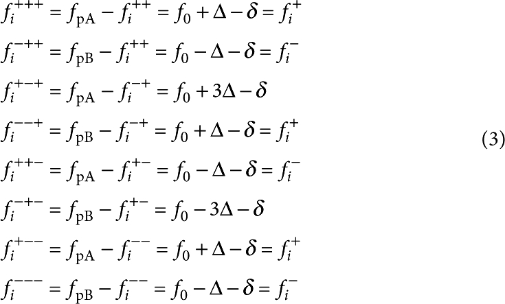
The mechanical oscillator response when injected with two detuned pumps with fixed frequency, fpA=2f0+Δ and fpB=2f0−Δ, while the system is also excited by fs=f0+δ is shown in Figure 2c. This measurement reveals a striking response from the mechanical oscillator with the observation of two first-order idlers
 |
1 |
two second-order idlers
 |
2 |
as well as two third-order idlers
 |
3 |
which arise because of the mixing of the pumps with first and second-order idlers (Fig. 2d shows all the idlers marked). Moreover, by varying Δ, the idlers can be detuned around f0 where larger values of Δ result in the higher order idlers becoming less visible as shown in Supplementary Figure S1c, that is, the idlers can only be observed within the bandwidth of the fundamental mode (Supplementary Note 3 and Supplementary Figure S4).
Numerical simulations
The experimental measurements can be verified by simulating the response of the non-degenerate parametric oscillator with an equation of motion given by
| 4 |
where x(t) is the resonator's position with damping γ=1/Q and an effective spring constant  containing a Duffing type nonlinearity parameterized by β and the parametric nonlinearity where Γ is the amplitude of the parametric modulation (pump) and Λ is the amplitude of the harmonic excitation (signal) where the signal and pump frequencies are given by
| 5 |
| 6 |
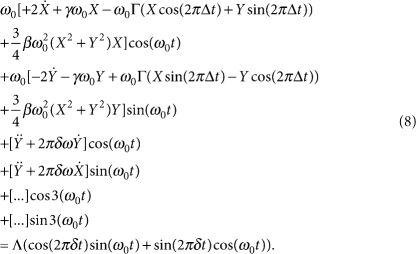
Equation (4) is solved in the rotating frame at ω0 by decomposing the resonator's position into in-phase and quadrature components
| 7 |
where X(t) and Y(t) are slowly varying compared with ω0. Equation (4) can thus be expressed as
 |
8 |
Neglecting the off-resonance coefficients yields two first-order nonlinear differential equations
 |
 |
9 |
Equation (9) can be readily modified to introduce n additional pumps as
 |
10 |
Additional signal excitations can also be introduced into equation (9) as
 |
11 |
where φ is the phase difference between the signal excitations s1 and s2. Equation (9) can be numerically solved using Euler's algorithm and the resulting amplitude at f0+δ is extracted by taking the Fourier transform F of X and Y as (F(X)−iF(Y))/2.
Numerical simulations using this formulism can reproduce all the experimental results with β=0 and Γ=0.9γ, that is, just below the parametric resonance threshold where mixing between the signals and pumps is mediated by the parametric term (mixing mediated by the Duffing term, that is, β≠0 is discussed in Supplementary Note 4 and is shown in Supplementary Figure S5).
Author contributions
I.M. conceived the idea, designed and fabricated the electromechanical resonator and constructed the measurement. I.M. and E.F. performed the measurements and analysed the data. K.N. and A.F. fabricated the Si-nanoFET amplifiers. I.M., E.F. and H.Y. developed the logic gates and circuits. All authors discussed the results, I.M. and H.Y. wrote the paper and H.Y. planned the project.
Additional information
How to cite this article: Mahboob, I. et al. Interconnect-free parallel logic circuits in a single mechanical resonator. Nat. Commun. 2:198 doi: 10.1038/ncomms1201 (2011).
Supplementary Material
Supplementary Notes 1-4 and Supplementary Figures S1-S5
Acknowledgments
We are grateful to S. Miyashita for synthesizing the heterostructure, and N Lambert, H Takesue and S Camou for comments. This work was partly supported by JSPS KAKENHI (20246064).
References
- Horak R. Telecommunications and Data Communications Handbook (Wiley, 2007). [Google Scholar]
- Brackett C. A. Dense wavelength division multiplexing networks: principles and applications. IEEE J. Sel. Areas Commun. 8, 948–964 (1990). [Google Scholar]
- Yoo S. J. B. Wavelength conversion technologies for wdm network applications. J. Lightwave Technol. 14, 955–966 (1996). [Google Scholar]
- Boole G. An Investigation of the Laws of Thought (Prometheus Books, 2003), originally published in 1854. [Google Scholar]
- Roukes M. Nanoelectromechanical systems face the future. Phys. World 14, 25–31 (2001). [Google Scholar]
- Ekinci K. L. & Roukes M. L. Nanoelectromechanical systems. Rev. Sci. Instrum. 76, 061101 (2005). [Google Scholar]
- Mahboob I. & Yamaguchi H. Bit storage and bit flip operations in an electromechanical oscillator. Nat. Nanotechnol. 3, 275–279 (2008). [DOI] [PubMed] [Google Scholar]
- Hayashi C. Nonlinear Oscillations in Physical Systems (Princeton University Press, 1986). [Google Scholar]
- Rugar D. & Grütter P. Mechanical parametric amplification and thermomechanical noise squeezing. Phys. Rev. Lett. 67, 699–702 (1991). [DOI] [PubMed] [Google Scholar]
- Mahboob I. & Yamaguchi H. Piezoelectrically pumped parametric amplification and Q enhancement in an electromechanical oscillator. Appl. Phys. Lett. 92, 173109 (2008). [Google Scholar]
- Shen Y. R. The Priciples of Nonlinear Optics (Wiley, 1984). [Google Scholar]
- Armstrong J. A., Bloembergen N., Ducuing J. & Pershan P. S. Interactions between light waves in a nonlinear dielectric. Phys. Rev. 127, 1918 (1962). [Google Scholar]
- Giordmaine J. A. & Miller R. C. Tunable coherent parametric oscillation in LiNbO3 at optical frequencies. Phys. Rev. Lett. 14, 973–976 (1965). [Google Scholar]
- Swade D. The Difference Engine: Charles Babbage and the Quest to Build the First Computer (Viking, 2001). [Google Scholar]
- Bardeen J. & Brattain W. H. The transistor, a semi-conductor triode. Phys. Rev. 74, 230–231 (1948). [Google Scholar]
- Roukes M. L. Mechanical computation, redux? IEEE IEDM Techn. Digest 539–542 (2004). [Google Scholar]
- Badzey R. L., Zolfagharkhani G., Gaidarzhy A. & Mohanty P. A Controllable nanomechanical memory element. Appl. Phys. Lett. 85, 3587–3589 (2004). [Google Scholar]
- Blick R. H., Qin H., Kim H.- S. & Marsland R. A nanomechanical computer-exploring new avenues of computing. N. J. Phys. 9, 241 (2007). [Google Scholar]
- Masmanidis S. C. et al. Multifunctional nanomechanical systems via tunably coupled piezoelectric actuation. Science 317, 780–783 (2007). [DOI] [PubMed] [Google Scholar]
- Guerra D. N. et al. A noise-assisted reprogrammable nanomechanical logic gate. Nano Lett. 10, 1168–1171 (2010). [DOI] [PubMed] [Google Scholar]
- Unterreithmeier Q. P., Faust T. & Kotthaus J. P. Nonlinear switching dynamics in a nanomechanical resonator. Phys. Rev. B 81, 241405(R) (2010). [Google Scholar]
- International Technology Roadmap for Semiconductors, 2009 Edition, Emerging Reserach Devices. http://public.itrs.net/.
- Mahboob I., Nishiguchi K., Fujiwara A. & Yamaguchi H. Room temperature piezoelectric displacement detection via a silicon field effect transistor. Appl. Phys. Lett. 95, 233102 (2009). [Google Scholar]
- Rahman M. S. et al. Device-level vacuum packaging for RF MEMS. J. Microelectromech. Syst. 19, 911–918 (2010). [Google Scholar]
- Verbridge S. S., Ilic R., Craighead H. G. & Parpia J. M. Size and frequency dependent gas damping of nanomechanical resonators. Appl. Phys. Lett. 93, 013101 (2008). [Google Scholar]
- O'Connell A. D. et al. Quantum ground state and single-phonon control of a mechanical resonator. Nature 464, 697–703 (2010). [DOI] [PubMed] [Google Scholar]
- Huang X. M. H., Zorman C. A., Mehregany M. & Roukes M. L. Nanodevice motion at microwave frequencies. Nature 421, 496 (2003). [DOI] [PubMed] [Google Scholar]
- Mashoff T. et al. Bistability and oscillatory motion of natural nanomembranes appearing within monolayer graphene on silicon dioxide. Nano Lett. 10, 461–465 (2010). [DOI] [PubMed] [Google Scholar]
Associated Data
This section collects any data citations, data availability statements, or supplementary materials included in this article.
Supplementary Materials
Supplementary Notes 1-4 and Supplementary Figures S1-S5


