Abstract
A computer numerical control-machined plexiglas-based microchip module was designed and constructed for the integration of blood sample preparation and nucleic acid amplification reactions. The microchip module is comprised of a custom-made heater-cooler for thermal cycling, a series of 254 μm × 254 μm microchannels for transporting human whole blood and reagents in and out of an 8–9 μL dual-purpose (cell isolation and PCR) glass-silicon microchip. White blood cells were first isolated from a small volume of human whole blood (<3 μL) in an integrated cell isolation–PCR microchip containing a series of 3.5-μm feature-sized “weir-type” filters, formed by an etched silicon dam spanning the flow chamber. A genomic target, a region in the human coagulation Factor V gene (226-bp), was subsequently directly amplified by microchip-based PCR on DNA released from white blood cells isolated on the filter section of the microchip mounted onto the microchip module. The microchip module provides a convenient means to simplify nucleic acid analyses by integrating two key steps in genetic testing procedures, cell isolation and PCR and promises to be adaptable for additional types of integrated assays.
The development of integrated DNA analysis devices remains an important challenge. Only a few prototype integrated DNA analysis devices that perform sample preparation, the analytical reaction, and the detection/quantitation steps have been described (Table 1) (Woolley et al. 1996; Burns et al. 1998; Waters et al. 1998; Brown 1999; Anderson et al. 2000), and most do not integrate the sample preparation step of the analysis (Woolley et al. 1996; Burns et al. 1998; Waters et al. 1998). This is because the sample preparation step is often the most difficult step in an assay, particularly for complex mixtures such as biological fluids. Thus, it is typically performed separately from the biochemical reaction and the detection/quantitation steps. The design flexibility of microchips fabricated from glass or silicon has facilitated the efficient isolation of white blood cells (WBCs) from human whole blood, as part of sample preparation for the polymerase chain reaction (PCR). For example, nucleated WBCs isolated in a glass-silicon microchip have been used directly in microchip-based PCR (Cheng et al. 1996a; Wilding et al. 1998). Different designs and sizes of filter, including simple arrays of posts, tortuous channels (Wilding et al. 1994), comb-shape filters (Cheng et al. 1996b) and weir-type filters (Wilding et al. 1998) have been incorporated in microchips and tested using human cells. Also, different designs of silicon microfilters (3–10 μm) have been fabricated across microchannels, and their filtration efficiency has been demonstrated using fluorescent beads and lymphocytes (Brody et al. 1995; Fiehn et al. 1995; Fluitman et al. 1995). In our previous study, we fabricated dual-purpose microchips for performing cell isolation and PCR (Wilding et al. 1998). An integrated cell isolation-PCR microchip was first mounted onto a microchip holder to perform WBC isolation, and the microchip was then placed on a Peltier heater/cooler device for PCR thermal cycling. Disadvantages of this system were that sample injection, cell isolation, and PCR were not performed on a single microchip-based device; this increased the risk of sample loss or contamination, and the analysis required some manual steps. More recently, we designed and constructed a plexiglas microchip module (Fig. 1A,C) for blood sample preparation and nucleic acid amplification reactions.
Table 1.
Prototype Integrated DNA Analysis Devices
| Sample preparation | Biochemical reactions | Detection | Fabrication methods for device | References |
|---|---|---|---|---|
| RNA purification from 1 mL of serum samples spiked with different copy numbers of an RNA transcript that contained a partial HIV sequence | Reverse transcription-PCR, nested PCR, DNase fragmentation and dephosphorylation, and terminal transferase labeling | GeneChip hybridization | conventional computer-controlled (CNC) machining | Anderson et al. 2000 |
| N/A | strand displacement amplification using on-device heater to provide thermal heating | electrophoresis | standard microfabrication techniques | Burns et al. 1998 |
| N/A | multiplex PCR using commercial thermal cycler to provide thermal cycling | electrophoresis | standard microfabrication techniques | Waters et al. 1998 |
| N/A | PCR using on-device heater to provide thermal cycling | electrophoresis | standard microfabrication techniques | Woolley et al. 1998 |
| White blood cells isolation form <3 μL of human whole blood | PCR using on-device heater-cooler to provide thermal cycling | N/A | conventional CNC machining (standard microfabrication techniques for microchips) | Plexiglas microchip module (Figure 1A, B) |
Figure 1.
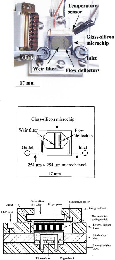
(A) Plexiglas microchip module. Dimensions: 40 mm × 40 mm × 19.175 mm. (B) Schematic diagram of the plexiglas microchip module. (C) Cross-section of the mounting of a glass-silicon microchip on the microchip module (not to scale) showing the major components (see text for details).
RESULTS
Microchip Scale Models
In our previous studies (Wilding et al. 1994, 1998; Cheng et al. 1995, 1996a,c; Shoffner et al. 1996), the microchip flow chamber design was based on a pragmatic approach in the absence of computational or modeling tools for microchip microfluidic design. With the rapid development of computational fluid dynamic simulation, this type of software would be an ideal tool for microchip design. However, in view of the high cost of this specialized software, we investigated a simpler and less expensive method that involved constructing microchip scale models.
Time-lapse photography revealed the desired uniform flow pattern across the flow chamber in a four-to-one microchip scale model (i.e., the model is four times the size of the microchip) containing flow deflectors (Fig. 2A). Also, time-lapse photography for one-to-one microchip scale models with glass flow chamber surfaces revealed a more uniform flow in the presence of flow deflectors (cf. Fig. 2B,C). Both the four-to-one (Fig. 2A) and the one-to-one (Fig. 2B) microchip scale models had very similar flow behavior in the presence of flow deflectors. Glass-silicon microchip designs (100 μm deep, 14 mm × 17 mm, 8–9 μL flow chamber volume) based on the results of the microchip scale models were fabricated. The flow behavior of the glass-silicon microchip with a straight weir-type filter (400 μm wide) and flow deflectors (Fig. 2D) was predicted by both the four-to-one (Fig. 2A) and the one-to-one (Fig. 2B) microchip scale models. The experimental results revealed that the microchip scale models are a simple way of assessing microfluidics prior to microchip fabrication.
Figure 2.
Time-lapse photography (from (i) to (iii)). Uniform flow pattern across the flow chamber is the desired flow behavior. Flow rate: 73 μL/min (syringe pump setting 6 mL/min). (A) Four-to-one microchip scale model with flow deflectors (rectangles inside the chamber next to the entry port). (B) One-to-one microchip scale model with flow deflectors (rectangles). (C) One-to-one microchip scale model without flow deflectors. (D) Glass-silicon microchip.
Cell Isolation and PCR in the Microchip Module
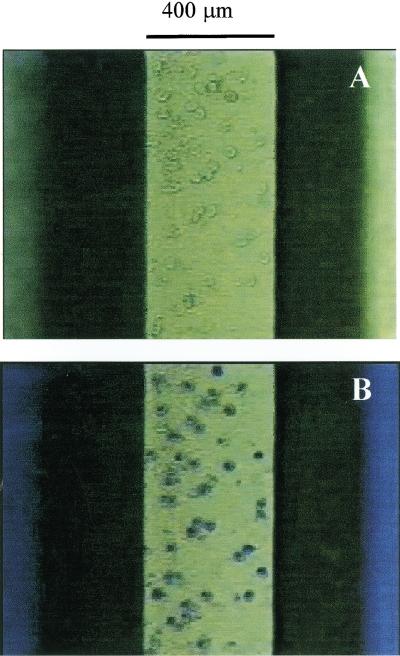
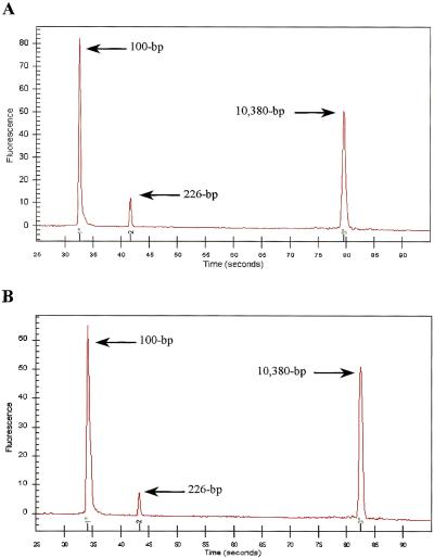
Microscopic inspection of the integrated cell isolation-PCR microchip mounted on the plexiglas microchip module showed that WBCs were trapped on top of the 400 μm-wide weir filter beneath the underside of the glass cover; no red blood cells (RBCs) could be discerned after staining the trapped cells with new methylene blue (Fig. 3). Quantitative capillary electrophoresis analysis of the PCR reaction for the human coagulation Factor V gene showed successful amplification (226 bp) for both the positive control (Fig. 4A) and for the integrated cell isolation and PCR performed in the microchip module (Fig. 4B). The successful amplification demonstrated that the microchip module provides a convenient means to simplify nucleic acid analyses by integrating two key steps in genetic testing procedures, cell isolation and PCR.
Figure 3.
Microscopic view from the top of an integrated cell isolation-PCR microchip mounted on the plexiglas microchip module. (A) WBCs isolated by the 400 μm wide weir-type filter. (B) New methylene blue-stained WBCs isolated by the weir-type filter.
Figure 4.
(A) Electropherogram of human coagulation Factor V amplification in the plexiglas microchip module with a PCR microchip containing 1000 WBCs isolated by the conventional test tube method from human whole blood. (B) Electropherogram of human coagulation Factor V amplification by integrated cell isolation and PCR in the plexiglas microchip module.
DISCUSSION
A genomic target, a region in the human coagulation Factor V gene (226-bp), was directly amplified by microchip-based PCR on DNA released from WBCs isolated on the filter of an integrated cell isolation-PCR microchip mounted onto a plexiglas microchip module (Fig. 1A,C). Sample injection, cell isolation and PCR were performed on the microchip module, unlike our previous study (Wilding et al. 1998), wherein a microchip was mounted onto a microchip holder to perform cell isolation and the microchip was then placed on a Peltier heater/cooler device for thermal cycling. The computer numerical control (CNC)-machined plexiglas microchip module is comprised of two main components: a replaceable glass/silicon filter-PCR microchip and the plexiglas- based unit, which consists of upper and lower plexiglas blocks, sandwiching a middle vinyl sheet and a custom-made heater/cooler. The etch depth, and hence glass-silicon microchip volume, was based on practical considerations for handling and analyzing microvolumes of reaction mixtures in a research and development environment. Previous microchip design experience revealed some limitations on etch depth, that is, the flow chamber could not be etched too deeply in the presence of weir-type filters (∼3.5 μm of filter gap), because as the chamber depth increases, the fluid flow pressure increases dramatically across the filters and in some cases caused the microchip to break.
The efficiency of the weir-type filter depends on the size of the filter, design of the filter, dilution of the blood sample, viscosity of the medium, and the filtration flow rate, that is, the applied pressure (Cheng et al. 1998; Wilding et al. 1998). Due to the deformability of human blood cells, higher filtration flow rates resulted in poor WBC isolation efficiency as the deformable WBCs passed through the weir-type filter. Lower filtration flow rates increased the WBC isolation efficiency but also increased the time required to eliminate the red blood cells (RBCs). As a result, clusters of RBCs formed and adhered to the bottom of the flow chamber inside the glass-silicon microchip, which increased the contamination, and hence possible inhibition, of the PCR reaction (McCusker et al. 1992; Wilding et al. 1998). We also found that for filtration experiments with long contact times, WBCs and RBCs adhered to the flow chamber and it was impossible to release them without cell lysis buffers. Therefore, the flow chamber surfaces of each microchip were first treated with 0.01% (v/v) of Triton X-100. The efficiencies of WBC isolation and RBC elimination, and hence the filtration time, were significantly improved with Triton X-100. For example, the filtration time was reduced to <10 min. Without Triton X-100, a red cell lysis buffer (Boehringer Mannheim) would be needed at the final phase of the cell isolation process in order to achieve >99.9% efficiency of RBC elimination; that is, <50 RBCs remained from the estimated 14,400,000 RBCs pumped into the microchip (data not shown). Microscopic inspection (100×) revealed that ∼1000 WBCs from the estimated 15,000 WBCs pumped into the microchip were visible on the top of the weir-type filter after being stained with New methylene blue (A.J.P. Scientific). In addition to the countable WBCs trapped on the top of the filter, we found many partially visible clumps of WBCs trapped on the leading slope of the filter which could not be counted. The slope leading to the top of the filter is a consequence of the conventional wet etching process used in fabricating the microchips. As part of the positive control, successful microchip-based PCR amplification performed in the microchip module was achieved with 1000 WBCs isolated from human whole blood as the genomic template (Fig. 4A). However, we found that in tube-based PCR, 2000 WBCs present in 10 μL of PCR assay mixture led to inhibition (data not shown). A similar result was obtained in the microchip-based PCR amplification. We speculate that this inhibition was due to the presence of residual protein (nuclear and cytoplasmic) released from the lysis of WBCs during the initial high-temperature step in the PCR (95°C for 5 min).
During operation, the blood sample and PCR assay mixture will only be in contact with the microchannels machined in the upper plexiglas block, the middle vinyl sheet, and the glass-silicon microchip (Fig. 1C). Therefore, reuse of these components will require cleaning to ensure the absence of DNAases, RNAases and other contaminants. In this study, only the glass-silicon microchip was disposed after each use (merely for our own convenience). However, based on the cost of the upper plexiglas block and the middle vinyl sheet (estimated to be ∼$5–$10 including labor and materials), they could also be discarded after each experiment.
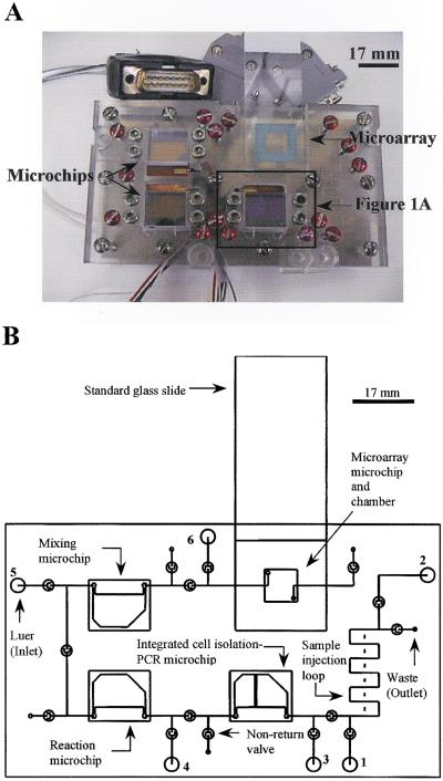
A prototype, next-generation CNC-machined plexiglas device (Fig. 5A,B) indicates further expansion of the filter–PCR microchip plexiglas module (Fig. 1A,C) to house more than one glass-silicon microchip for additional sequential operations such as PCR product manipulation, enzyme digestion, sample mixing, and microarray detection. A system of microvalves, based on a discontinuous microchannel and the flexible plastic membrane (Yuen et al. 2000), and microchannels will connect the individual microchips and microarray in series. In-platform heater/coolers previously validated in our first generation system (the enclosed rectangle in Figure 5A will have the same operation and function as the microchip module shown in Figure 1A) provide thermal cycling or incubation at a set temperature at individual microchip or microarray locations. Briefly, the proposed operation of the device will be as follows. A microvolume sample of human whole blood will first be injected into a sample injection loop (zigzag portion of the microchannels with a maximum volume of 5 μL), using a conventional syringe through the first luer inlet (Fig. 5B). The blood sample will then be pushed through an integrated cell isolation–PCR microchip through the second luer inlet with a PCR mixture (without any genome template). The cell isolation–PCR microchip will facilitate isolation of WBCs from the blood sample. PCR will be performed as described above and shown in Figure 1A. After thermal cycling, the PCR product will be transferred from the cell isolation–PCR microchip into a reaction microchip through the third luer inlet with additional reagents added from the fourth luer inlet to perform enzyme digestion or other biochemical reactions. Subsequently, after incubations, the treated PCR product will be transferred from the reaction microchip into a mixing microchip through the fourth luer inlet with addition reagents added from the fifth luer inlet. After incubation in the mixing microchip, the treated PCR product will be ready for detection. This treated PCR product will finally be transferred from the mixing microchip into a detection microarray through the fifth luer inlet with addition reagents added from the sixth luer inlet. After final incubation, the standard glass side will be taken out for scanning and detection. In this case, all analytical tasks (except the final scanning) will be performed on this integrated device, which minimizes or eliminates any sample loss or contamination.
Figure 5.
(A) Total integrated microchip device. Dimensions: 120 mm × 70 mm × 40 mm. (B) Schematic diagram of the total integrated microchip device.
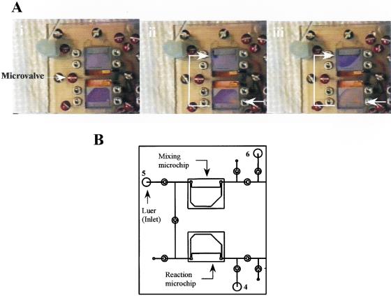
A series of sample transfer experiments were performed on the proposed integrated device to prove that the microfluidic network can indeed transfer a sample from the microchip to the microchip/detection microarray. Time-lapse photography showed successful sample transfer from a 12 μL reaction microchip to a 22 μL mixing microchip (Fig. 6A,B) performed on the proposed integrated device, thus demonstrating the feasibility of the sample transfer and the possible development of a total integrated microchip device.
Figure 6.
Sample transfer from a 12 μL reaction microchip to a 22 μL mixing microchip on the total integrated microchip device. Flow rate: 50 μL/min (syringe pump setting 5 mL/min).(A) Time-lapse photography [from (i) to (iii)]. (B) Schematic diagram.
METHODS
Microchip Scale Models
A template four times the size or the same dimensions of a glass-silicon microchip was cut from a 250 μm-thick membrane (3M Tape number 8672; 3M Industrial Tape and Specialties Division). The template was placed between two pieces of plexiglas/standard glass microscope slides to form the flow chamber, and clamps were used to fasten the plexiglas/glass slides together to prevent leakage. Two holes were machined through the bottom plexiglas/glass slide for the inlet and outlet of the microchip scale model. In some cases, a series of flow deflectors was incorporated into the microchip scale model to modify the flow behavior such that the flow pattern would be uniform across the flow chamber. In order to better mimic the inside surfaces of the glass-silicon microchip, the plastic flow chamber surfaces of the four-to-one microchip scale model was treated with 0.01% (v/v) of Triton X-100 (Sigma).
Glass-Silicon Microchips
Based on the results obtained from the microchip scale models, a series of 8–9 μL dual-purpose (cell isolation and PCR) 14 mm × 17 mm silicon microchips thermally coated with silicon oxide (2,000 ± 100Å thick) (a flow chamber depth of 100 ± 10 μm) was fabricated at the Cornell Nanofabrication Facility (Ithaca, NY) using standard photolithographic techniques (Shoffner et al. 1996; Wilding et al. 1998) on 560–590 μm-thick 100 mm-diameter silicon wafers. The principle of the weir-type filters and the choice of the size of the filter gap have been discussed previously (Cheng et al. 1998; Wilding et al. 1998). Briefly, a weir-type filter is formed by a block of silicon (weir) spanning a chamber or channel. A gap between the top of the weir and the glass cover of the chip serves to trap cells between the top of the weir and the underside of the glass cover.
Plexiglas Microchip Module
The microchip module was constructed from the following components: an upper plexiglas block (40 mm × 40 mm × 8 mm), a middle vinyl sheet (40 mm × 40 mm × 3.175 mm), a lower plexiglas block (40 mm × 40 mm × 8 mm), a custom-made heater/cooler, a replaceable glass-silicon microchip (17 mm × 14 mm), two gaskets (for sealing the exit/entry ports), a temperature sensor and two pieces of small plexiglas strips (Fig. 1A,C).
The upper plexiglas block, the middle vinyl sheet and the lower plexiglas block were manually fastened together by screws (Fig. 1C). The upper plexiglas block and the middle vinyl sheet housed the custom-made heater/cooler that was constructed from a copper block (11 mm × 11 mm × 6 mm) with channels drilled inside it for the inlet and outlet of flowing coolant, a standard thermoelectric cooling module (Part no. 9501/017/040B; Ferrotec America Corporation), and a copper plate. In this study, the flowing coolant was deionized water at room temperature flowing at 10 mL/min. Also, a temperature sensor (Model AD590, Omega Engineering) was glued at the corner of the copper plate to monitor the temperature during thermal cycling. The custom-made heater/cooler was supported on the lower plexiglas block, into which two channels were drilled for inlet and outlet of the cooling water. The glass-silicon microchip was placed directly on top of the heater/cooler with the silicon surface of the microchip accessible for contact with the heater/cooler for thermal cycling. The inlet and outlet of the microchip were connected to microchannels formed by the middle vinyl sheet sandwiched between the upper and lower plexiglas blocks. The function of this vinyl sheet was to cover open microchannels (254 μm × 254 μm) milled or drilled into the bottom of the upper plexiglas block to form fluid flow channels. Gaskets (3M Tape no. 8672; 3M Industrial Tape and Specialties Division) were placed between the microchip's inlet/outlet port and the microchannel's opening on top of the upper plexiglas block in order to prevent leakage. The microchip was held in place by two plexiglas strips on top of the upper plexiglas block, and additionally was spring-loaded by means of a compressible silicon rubber block made from a silicon rubber sealer (Archer cat. no. 64-2314B, custom-manufactured for Radio Shack) to facilitate efficient heat transfer between the microchip and the heater/cooler.
The open microchannels were first machined on the bottom surface of the upper block using a computer numerical control (CNC) machine (Fadal Engineering) with a 0.01 inch (254 μm) diameter end mill. A spindle speed of 6000 rpm and feed rate of 0.5 inch/min were used in order to produce smooth channel surfaces. Kerosene was used as the coolant during machining. Finally, openings for the heater/cooler and necessary holes and openings required for assembly were either milled or drilled into the various components.
Cell Isolation and PCR in the Microchip Module
The microchip was first primed with PBS (Dulbecco's 1× phosphate buffered saline without calcium chloride and magnesium chloride), which contained 0.01% (v/v) of Triton X-100, to ensure that there was no air remaining inside the microchip and no leakage was observed on the plexiglas microchip platform. Then, a small volume (<3 μL) of human whole blood (5400 WBCs/μL and 4,800,000 RBCs/μL) obtained from a fasting volunteer was pumped into the microchip. Directly following the injection of the whole blood, 100 μL of PCR assay mixture was pumped through the microchip from a 1 mL syringe at 9.85 μL/min (syringe pump, Model 341B; Sage Instruments, setting 11 mL/hr) to complete the cell isolation process. For human coagulation Factor V gene, a 100 μL of PCR assay mixture contained 2 μL of each primer (5 pM/μL), 10 μL of 10× reaction buffer (1.5 μM MgCl2), 2 μL of dNTPs (10 μM), 1 μL of AmpliTaq Gold DNA polymerase and 83 μL of water. The primer sequence information is as follows: forward primer FACV-3 (5′-TGC CCC ATT ATT TAG CCA GGA G-3′) and reverse primer FACV-5 (5′-ACC CAC AGA AAA TGA TGC CCA G-3′).
Finally, the microchip module was connected to a temperature control module (TCM-39032; ILX Lightwave), which was inserted into a computer-controlled modular laser diode controller (LDC-3900; ILX Lightwave), for thermal cycling. The reaction mixture in the microchip was initially heated to 95°C for 5 min and cycled for 40 cycles: 94°C for 1 min, 60°C for 1 min and 72°C for 1 min. A final extension was performed at 72°C for 5 min.
As a control, microchip-based PCR reactions using pre-isolated WBCs as a genome template were performed in the plexiglas microchip module. WBCs were isolated from human whole blood obtained from a fasting volunteer, and mixed with PCR assay mixture. Then, the WBC-spiked PCR assay mixture was injected into a 12 μL PCR microchip (Cheng et al. 1996b; Shoffner et al. 1996) which was then mounted onto the plexiglas microchip module to perform microchip-based PCR. In addition, PCR reactions were performed in MicroAmp tubes (Perkin-Elmer GeneAmp PCR System 2400) containing 10 μL of the same PCR assay mixture used in the microchip module. In this case, the PCR assay mixture contained 40 ng of genomic DNA. All PCR products were analyzed by quantitative capillary electrophoresis using the Agilent Bioanalyzer 2100 (Agilent Technologies) and a DNA 7500 LabChip kit.
Acknowledgments
This work was supported in part by a National Cancer Institute grant, RO1-CA 78848–01 (P.W. and L.J.K.) and the Comprehensive Sickle Cell Center through grant NIH-NHLBI P60-HL38632 (P.F., P.W., and L.J.K.).
The publication costs of this article were defrayed in part by payment of page charges. This article must therefore be hereby marked “advertisement” in accordance with 18 USC section 1734 solely to indicate this fact.
Footnotes
EMAIL kricka@mail.med.upenn.edu; FAX (215) 662-7529.
Article and publication are at www.genome.org/cgi/doi/10.1101/gr.155301.
REFERENCES
- Anderson RC, Su X, Bogdan GJ, Fenton F. A miniature integrated device for automated multistep genetic assays. Nucleic Acids Res. 2000;28 E60:i–vi. doi: 10.1093/nar/28.12.e60. [DOI] [PMC free article] [PubMed] [Google Scholar]
- Brody JP, Osborn TD, Foster FK, Yager P. Proceedings of the 8th International Conference on Solid State Sensors and Actuators, and Eurosensors IX, Stockholm, Sweden. June. 1995. A planar microfabricated fluid filter. 779–782. [Google Scholar]
- Brown, S.F. 1999. Good-bye, test tubes hello, labs-on-a-chip. Fortune. October 11, 282–307.
- Burns M, Johnson RN, Brahmasandra SN, Handique K, Webster JR, Krishnan M, Sammarco TS, Man PM, Jones D, Heldsinger D, et al. An integrated nanoliter DNA analysis device. Science. 1998;282:484–487. doi: 10.1126/science.282.5388.484. [DOI] [PubMed] [Google Scholar]
- Cheng J, Shoffner MA, Zhang Q, Kricka LJ, Wilding P. Frederick Conference on Capillary Electrophoresis. Frederick, MD. 1995. Examination of microchip RT–PCR amplification product using entangled solution capillary electrophoresis (ESCE) with laser induced fluorescence detection (LIF) [Google Scholar]
- Cheng J, Fortina P, Surrey S, Kricka LJ, Wilding P. Microchip-based devices for molecular diagnosis of genetic diseases. Mol Diagnosis. 1996a;1:183–200. doi: 10.1016/s1084-8592(96)70004-8. [DOI] [PubMed] [Google Scholar]
- Cheng J, Shoffner MA, Hvichia GE, Kricka LJ, Wilding P. Chip PCR. II. Investigation of different PCR amplification systems in micro-fabricated silicon-glass chips. Nucleic Acids Res. 1996b;24:380–385. doi: 10.1093/nar/24.2.380. [DOI] [PMC free article] [PubMed] [Google Scholar]
- Cheng J, Shoffner MA, Mitchelson KR, Kricka LJ, Wilding P. Analysis of ligase chain reaction (LCR) products amplified in a silicon-glass chip using entangled solution capillary electrophoresis. J Chromatogr A. 1996c;732:151–158. doi: 10.1016/0021-9673(95)01257-5. [DOI] [PubMed] [Google Scholar]
- Cheng J, Kricka LJ, Sheldon EL, Wilding P. Sample preparation in microstructured devices. Topics Curr Chem. 1998;194:216–231. [Google Scholar]
- Fiehn H, Howitz S, Pham MT, Vope T, Burger M, Wegener T. Components and technology for a fluidic-ISFET-microsystem. In: van den Berg A, Bergveld P, editors. Micro total analysis systems. Norwell, MA: Kluwer Academic Publishers; 1995. pp. 289–293. [Google Scholar]
- Fluitman JH, van den Berg A, Lammerink TS. Micromechanical components for μTAS. In: van den Berg A, Bergveld P, editors. Micro total analysis systems. Norwell, MA: Kluwer Academic Publishers; 1995. pp. 73–83. [Google Scholar]
- Shoffner MA, Cheng J, Hvichia G E, Kricka LJ, Wilding P. Chip PCR. I. Surface passivation of microfabricated silicon-glass chips for PCR. Nucleic Acids Res. 1996;24:375–379. doi: 10.1093/nar/24.2.375. [DOI] [PMC free article] [PubMed] [Google Scholar]
- McCusker J, Dawson MT, Noone D, Gannon F, Smith T. Improved method for direct PCR amplification from whole-blood. Nucleic Acids Res. 1992;20:6747. doi: 10.1093/nar/20.24.6747. [DOI] [PMC free article] [PubMed] [Google Scholar]
- Waters LC, Jacobson SC, Kroutchinina N, Khandurina J, Foote RS, Ramsey JM. Microchip device for cell lysis, multiplex PCR amplification, and electrophoretic sizing. Anal Chem. 1998;70:159–162. doi: 10.1021/ac970642d. [DOI] [PubMed] [Google Scholar]
- Wilding P, Kricka LJ, Cheng J, Hvichia G, Shoffner M, Fortina P. Integrated cell isolation and polymerase chain reaction analysis using silicon microfilter chambers. Anal Biochem. 1998;257:95–100. doi: 10.1006/abio.1997.2530. [DOI] [PubMed] [Google Scholar]
- Wilding P, Pfahler J, Bau HH, Zemel JN, Kricka LJ. Manipulation and flow of biological fluids in straight channels micromachined in silicon. Clin Chem. 1994;40:43–47. [PubMed] [Google Scholar]
- Woolley AT, Hadley D, Landre P, de Mello AJ, Mathies RA, Northrup MA. Functional integration of PCR amplification and capillary electrophoresis in a microfabricated DNA analysis device. Anal Chem. 1996;68:4081–4086. doi: 10.1021/ac960718q. [DOI] [PubMed] [Google Scholar]
- Yuen PK, Kricka LJ, Wilding P. Semi-disposable microvalves for use with microfabricated devices or microchips. J Micromechanics Microeng. 2000;10:401–409. [Google Scholar]


