

Abstract
Accurate structure determinations by X-ray crystal analysis and computation using semi-empirical self-consistent field molecular orbital calculations are described and compared for 4-bromodiphenyl ether (PBDE 3), the 13C6-isotopic labeled PBDE 3 (13C6-PBDE 3) and its five corresponding monofluorinated analogues (F-PBDEs 3): 2-fluoro-4-bromodiphenyl ether (F-PBDE 3-2F), 2′-fluoro-4-bromodiphenyl ether (F-PBDE 3-2′F), 3-fluoro-4-bromodiphenyl ether (F-PBDE 3-3F), 3′-fluoro-4-bromodiphenyl ether (F-PBDE 3-3′F) and 4′-fluoro-4-bromodiphenyl ether (F-PBDE 3-4′F). The synthesis and full characterization by means of 1H, 13C, 19F nuclear magnetic resonance spectroscopy and mass spectrometry of the F-PBDEs 3 are presented for the first time. Intermolecular interactions for PBDE 3 and the F-PBDEs 3 isomers were dominated by weak C-H(F,Br) ····π and C-H····F interactions. The bond lengths of C-F varied between 1.347(2) Å and 1.362(2) Å, C4-Br between 1.880(3) Å and 1.904(19) Å. Both correlated with electron-density differences as determined by 13C shifts, but not with the strength of C-F couplings. The interior ring angles at ipso-fluoro-substitution increased to 121.95° due to hyperconjugation by p-π-orbital overlapping, a phenomenon that was also computed. An attraction between the vicinal fluoro-and bromo-substituents was not determined, as seen in fluoro-substituted chlorobiphenyls. The torsion angles measured and computed for the series of PBDE 3 and F-PBDEs 3 differed strongly from each other. Since the ether linkage (an average of 2.76 Å) provides more distance and the bonds are flexible up to a certain range, the influence of a fluoro-substituent is only detectable in PBDEs with high ortho-substitution. A concordance of computed and measured torsion angles can be observed with increasing size and/or grade of substitution comparing mono- to tetra- fluoro-, chloro-, bromo- and methyl-substitutions in the ortho-positions of diphenyl ether. Differences between computational versus measured data demonstrates a strong need to evaluate the results against independent techniques to conclude structure receptor activity relationships of PBDEs. Any discussion of the Ah or other biological receptor activity of certain PBDEs should take this in consideration. For the first time a complete overview of known and hypothetical biological activities of PBDEs is presented.
1. Introduction
Polybrominated diphenyl ethers (PBDEs) are a class of 209 individual congeners, distinguishable by the number and position of bromines in the rings. PBDEs are extensively in use as flame-retardants and commonly added to consumer goods e.g. high-impact polystyrene, foams, textiles, wire and cable insulation, conductors plastics, polyurethane foams and textiles (Bromine Science and Environment Forum 2003; Nordic Council of Ministers, 1998) and Christmas Goats (Zeller, 2006). PBDEs are incorporated into materials using an “additive” process and thus may slowly volatilize into the environment during the product’s lifetime (Sjödin, et al., 2001). In fact, some polyurethane foam is treated with 10–30 wt % of PBDEs (Hale, et al., 2002). Recent studies have shown that PBDEs are globally distributed and detected in most environmental media including air (Strandberg, et al., 2001; Gouin, et al., 2002; Harner, et al. 2002, Hoh & Hites, 2005), water (Ikonomou, et al., 2002a), soil (WHO, 1994), sediment (Sellström, et al., 1998; Allchin, Law & Morris, 1999; Eljarrat & Barcelo, 2004; Zhu & Hites, 2005), vegetation (Gouin, et al. 2002; de Boer, 2003) and biota (Ikonomou, et al. 2002a, b; ter Schure, et al., 2002).
PBDEs are now ubiquitous contaminants and due to their lipophilic character, high bioavailability and slow elimination, they bioaccumulate in the body and biomagnify in the food web (Meironyte, Noren & Berman, 1999; Lind et al., 2002; Hites, 2004; Darnerud et al., 2001; Bergman et al., 1999; Ryan & Patry, 2000; Johanson-Restrepo, Kannan & Raport, 2005; Hites et al., 2005). The environmental levels of PBDEs are in general still lower than those of polychlorinated biphenyls (PCBs). However, while the levels of PCBs, and many other chlorinated contaminants are gradually decreasing, the levels of PBDEs are rapidly increasing. Furthermore PBDE levels found in people living in North America are currently 10 to 100 times higher than those in Europe or Japan, and are doubling every 4–6 years (Hites, 2004; Johanson-Restrepo, Kannan & Raport, 2005). As PBDE levels increase so does the public health threat; there is concern of their potential for liver toxicity, disruption of thyroid hormone homeostasis, neurotoxicity, reproductive and developmental toxicity and carcinogenicity.
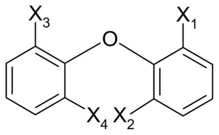
Knowledge of PBDEs crystal structures and homology models to examine potential moded for ligand binding is fundamental to our understanding of the biological activity of PBDEs as agonists and antagonists. This is the basis for quantitative structure-activity relationships that can be constructed from those data to understand the ligand binding to cellular and nuclear receptors, as mediators of signaling, and gene expression. Receptor activity is of special interest since PBDEs show little metabolic activity. Currently this knowledge is extremely limited and very controversially. For the first time a complete overview of biological transcription factors activated by PBDEs is presented (see Table 1). The structural similarity of certain PBDE congeners to other polyhalogenated aromatic compounds, e.g. polychlorinated biphenyls (PCBs), has raised the question whether PBDEs might be active aryl hydrocarbon receptor (Ah) mediated effects. Several groups found agonistic and antagonistic activity for certain PBDEs, see Table 1. On the other hand, it is claimed that these effects result not from the PBDEs themselves, but from polybrominated dibenzofurans (PBDFs) which are present in the test compounds as impurities (Sanders et al., 2005). Since the non-planar PBDEs show week agonism compared with ‘co-planar dioxin-like’ Ah receptor ligands and steroid, heme and xenobiotic metabolism are controlled by a network of interrelated receptors, additional receptors and functions have been studied or hypothesized for PBDEs, i.e. constitutive androstane (CAR), pregnane × (PXR), peroxisome proliferator (PPAR), ryanodin (RyR), estrogen (ER(α,β)), androgen (AR), progesterone (PR), thyroid function (TH), glucocorticoid (GR), γ-aminobutyric acid (GABA), thyroxine (T4), insulin-like growth factor-I (IGF-I), dihydrotestosterone (DHT) and dioxin response element (DRE), see Table 1. The orphan receptors CAR and PXR activities are also of interest, since it was observed that they activate each other by “cross-talk” (Kretschmer & Baldwin, 2005). Central in the receptor ligand acticity is the conformation of the ligand, e.g. PBDE. The conformations of diphenyl ethers are described by the torsional angles (ϕ1 and ϕ2) between the C1–O–C1′ plane and planes of the phenyl rings. The angles are defined as positive when the rotation is clockwise looking down the C4–C1 and C4′–C1′ axes toward the oxygen. Conformational properties of variously substituted diphenyl ethers have previously been studied using semiempirical or ab initio calculations (Nevalainen & Rissanen, 1994; Hu et al., 2005; Luthe et al. 2006). Theoretically, there are four possible types of conformations of diphenyl ethers: planar (ϕ1 = ϕ2 = 0°), butterfly (ϕ1 = ϕ2 = 90°), skew (ϕ1= 0°, ϕ2= 90°) and twist (ϕ1, ϕ2 > 0°). A variety of experimental and theoretical studies have shown that the unsubstituted diphenyl ether itself has a twist conformation in that ϕ1 and ϕ2 lie in the vicinity of 25–50° (Schaefer et al., 1988). PBDE congeners prefer a skew or twist conformation depending on the number of the ortho-bromo-substituents (Nevalainen & Rissanen, 1994). One approach to gaining information about the three-dimensional structure of PBDEs of single crystals by X-ray analysis or solid state nuclear magnetic resonance spectroscopy, another is to compute bond lengths and angles under ideal vacuum conditions. All approaches have drawbacks in modeling the molecular structure in solution, which makes it necessary to compare and interpretate the obtained results from both approaches. Unfortunately, relatively few crystal structures of PBDEs have been reported or computed to understand quantitative structure activity relationships (QSAR) in biological systems. 4-Bromodiphenyl ether (PBDE 3) is the most fundamental PBDE and therefore ideal to study conformational changes to gain information which can be generalized.
Table 1. Receptor/enzyme interactions of PBDEs. For a more complete review see Luthe et al. (2007b).
Please note that direct binding of the PBDEs themselves may not have been demonstrated, but is inferred by effect. Also note that the levels of the receptors themselves might be influenced by the PBDEs themselves.
| Receptor abbreviation | Gene or function affected |
PBDEs |
|
|---|---|---|---|
| Ligands | Response and references | ||
| Aryl hydrocarbon (AhR) | CYP 1A | PBDEs 3, 15, 17, 28, 47, 49, 66, 71, 75, 77, 85, 99, 100, 119,126, 152, 153154, 183, 6-OH-PBDE 47 47, PBDE mixture (D-71) PBDF impurities |
agonists, weak to moderate (Wang et al., 2006; Chen & Bruce, 2003; Peters et al., 2006a; Peters et al., 2006b; Germer et al., 2006; ) antagonist in fish, weak (Kuiper et al., 2004) no Ah activity by PBDEs, but from PBDFs impurity (Sanders et al., 2005) |
| Constitutive androstane (CAR) | CYP 2B | PBDE mixtures DE-71, PBDE 79 | weak (Kretschmer & Baldwin, 2005; Carlson, 1980; Sanders et al. 2005; Germer et al., 2006) |
| Pregnane X (PXR) | CYP 3A | PBDE mixture D-71 | (Germer et al., 2006) |
| Peroxisome proliferator (PPAR) | CYP 4A | Ah active PBDEs and potentially PBDFs | suggested repression in analogy to PCBs (Ariyoshi et al., 1998) |
| Ryanodin (RyR) | Ca2+ channel | Non co-planar PBDEs and OH-PBDEs | Suggested agonist in analogy to the findings in PCBs (Pessah et al., 2006) |
| Estrogen (ER) | Estrogen | OH-PBDE Di-OH-PBDE PBDE 99 |
(Kretschmer & Baldwin, 2005; Stoker et al., 2004; Meerts et al., 2001; Ceccatelli et al., 2006) |
| Androgen (AR) | Androgen | PBDE mixture DE-71, PBDEs 100 PBDEs 47, 99, 100, 153, 154 |
Suppression and inhibition (Stoker et al., 2005) competitive anti-androgenic (Stoker et al., 2005) |
| Progesterone (PR) | Progesterone | PBDE 99 | suppression (Ceccatelli et al., 2006) |
| Dihydro-testosterone (DHT) | Dihydrotestosterone | PBDE 47, 100 | Inhibitor transcriptional activation (Stoker et al., 2005) |
| Thyroid function (TH) | Thyroid hormone | OH-PBDEs PBDE 47 PBDE mixtures DE-71, 79 |
Agonist (Kretschmer & Baldwin, 2005; Eslami et al., 2006; Hallgren, Darnerud, 2002, Zhou et al., 2002) disruptor (Kretschmer & Baldwin, 2005) |
| Thyroxine (T4) | Thyroxine | PBDEs 71, 73, 125 | reducing serum T4 level (Kretschmer & Baldwin, 2005; Stoker et al., 2004; Hooper & McDonald, 2000; Zhou et al., 2002; Eslami et al., 2006) |
| Triiodothyronine (T3) | 4′OH-PBDE 27 | ||
| Glucocorticoid (GR) | Glucocorticoid | MeSO2-PBDE | suggested repression by competitive antagonism in analogy to MeSO2-PCBs (Johansson, Nilsson & Lund, 1998) |
| Insulin-like growth factor (IGF) | Insulin-like growth factor | PBDE 99 | agonist, weak (Ceccatelli et al., 2006) |
It is our hypothesis that fluoro-tagging can be employed to study biological activity of a given PBDE congener by varying its three dimensional structure. To test this hypothesis, we have synthesized and determined the crystal structures of a series of the five possible monofluorinated isomers (F-PBDEs 3) of the fundamental PBDE 3 isomer and compared these data with semiempirical self-consistent field molecular orbital (SCF-MO) calculations. Preliminary work on monofluorinated analogues of polycyclic aromatic hydrocarbons (F-PAHs) (Luthe, Ariese & Brinkman, 2002), polychlorinated biphenyls (F-PCBs) (Luthe et al., 2006a; Luthe, Swenson & Robertson, 2007) and polybrominated diphenylethers (F-PBDEs) in (Luthe et al., 2006b) were very promising. The physical and chemical properties of F-containing organic compounds are related to a number of distinctive characteristics of the fluorine atom, including its radius, which is much smaller than that of the homologue bromine. The van der Waals radii of fluorine and hydrogen are comparable, especially if C–F secondary binding (hyperconjugation) is taken into account (Luthe, Ariese & Brinkman, 2002). It is our aim to explore the potential of F-PBDEs to investigate biological activity in vitro and in vivo.
2. Experimental
2.1 Synthesis and characterization
Chemicals
Phenol (99%) (1a) and phenol-13C6 (99ATM% 13C) (1b) were purchased from Sigma Aldrich (St. Louis, MO, USA), 4-bromo-2-fluorophenol (99%) (1c), 3-fluorophenol (98%) (1f) and 4-fluorophenol (99%) (1g), 1,4-dibromobenzene (99%) (2a), bromobenzene (99%) (2b), copper-(I)-bromide (98%), magnesium sulfate and CDCl3 (99.8%) with TMS (0.03 %) from Acros (Morris Plains, NJ, USA), 1-fluorophenol (97%) (1d) from Maybridge (Morris Plains, NJ, USA) and 4-bromo-3-fluorophenol (97%) (1e) from Matrix Scientific (Columbia, SC, USA). Copper powder (mesh size 99,9%), potassium hydroxide (p.a.), methanol (p.a.), n-hexane (95%), acetonitrile, silica gel 60 Å C:C 40–63 μm were purchased from Fisher Chemical (Pittsburgh, PA, USA).
Synthesis
PBDE 3, 13C6-isotopic labeled PBDE 3 (13C6-PBDE 3) and F-PBDEs 3, i.e. 2-fluoro-4-bromodiphenyl ether (F-PBDE 3-2F), 2′-fluoro-4-bromodiphenyl ether (F-PBDE 3-2′F), 3-fluoro-4-bromodiphenyl ether (F-PBDE 3-3F), 3′-fluoro-4-bromodiphenyl ether (F-PBDE 3-3′F) and 4′-fluoro-4-bromodiphenyl ether (F-PBDE 3-4′F), were synthesized by nucleophilic substitution of bromobenzenes and by phenols. In the nomenclature, the first number refers to the corresponding PBDE, the second indicates the position of the substituend, e.g. fluorine, with the bromo-substituent having the highest priority. This Ballschmiter-Zell-Luthe (BZL) system (Luthe, 2006a, b,Luthe, 2007) corresponds easily to the broadly used BZ system (Ballschmiter & Zell, 1980) of the corresponding PBDEs. General procedure: A mixture of a phenol (1a–g) (10 mmol), potassium hydroxide (0.56 g, 10 mmol), bromobenzene (2a,b) (12 mmol), copper bromide (1.44 g, 10 mmol) and copper powder (0.64 g, 10 mmol) was heated under refluxing at 130°C for 2 h in acetonitril. For the reaction equation and yields, see Fig. 1.
Fig. 1.

Synthesis of the PBDE 3, 13C6-PBDE 3 and F-PBDEs 3 (3a–g) by nucleophilic substitution of bromobenzenes (2a–b) and phenols (1a–g). For details, see Experimental section.
Synthesis monitoring and clean-up procedure
The reactions were monitored and the purity of all compounds was determined by gas chromatography (GC) and thin layer chromatography (TLC). A GC (Varian 3800 Palo Alto, CA, USA) equipped with a flame ionization detector (FID) was used. Separation was performed on a CP-sil 5CB column (Chrompack, Darmstadt, Germany) 20 m × 0.25 mm ID., 0.25 μm film thickness. Nitrogen was used as carrier gas. The column temperature was programmed from 50 °C to 250 °C at 5 °C/min and hold for ten minutes. For TLC ALUGRAM SIL G/UV254, (Machery-Nagel, Düren, Germany) was used as stationary and n-hexane as mobile phase. After the reaction was completed the mixture was suspended in diethyl ether and the solution filtered of the employed magnesium sulfate. The solution was evaporated under reduced pressure and the crude product purified by column chromatography on a silica gel column with n-hexane as mobile phase. Impurities formed by brominated were removed under reduced pressure using a KUGEL-ROHR distillation. Flash chromatography was the method of choice for the purification processes. Silica gel was used as stationary and n-hexane as mobile phase. For 1 g of crude product ca. 300 g silica gel was used. All F-PBDEs 3 and PBDEs 3 were re-crystallized from methanol.
1H, 13C and 19F NMR characterization
PBDE 3, 13C6-PBDE 3 and F-PBDEs 3 were characterized by means of proton (1H), carbon (13C), fluorine (19F) nuclear magnetic resonance (NMR) spectroscopy and 13C 1H correlated spectroscopy (COSY). The 1H and 13C NMR spectra were recorded on 300 MHz NMR spectrometer (Bruker, Billerica, MA, USA), using CDCl3 as solvent. Chemical shifts, δ, are given in ppm relative to TMS, coupling constants, J, in Hz. The 13C NMR results are listed in Table 2, the ones of the 1H NMR are presented in the results chapter (3.2). 19F NMR spectra were obtained with a 5 mm QNP probe, operating at 282.4 MHz. Chemical shifts were calibrated against hexafluorobenzene as standard. An overview of the shifts and couplings is given in the results. Images of the COSY spectra are attached in the supplemental materials.
Table 2.
13C chemical shifts δ [ppm] relative to TMS, the 13C19F couplings J [Hz] over n bindings of all carbons in PBDE 3 and F-PBDE 3 F congeners. Numbering is according to the BZ, or the BZL systems.
| BZ/BZL no. | coupling | C-1 | C-2 | C-3 | C-4 | C-5 | C-6 | C-1′ | C-2′ | C-3′ | C-4′ | C-5′ | C-6′ |
|---|---|---|---|---|---|---|---|---|---|---|---|---|---|
| 3 | 156.8 | 120.6 | 132.9 | 115.8 | 132.9 | 120.6 | 156.9 | 119.2 | 130.1 | 123.9 | 130.1 | 119.2 | |
| 3-2F | 143.5 | 154.3 | 120.8 | 116.2 | 128.0 | 122.9 | 157.0 | 117.7 | 130.0 | 123.8 | 130.0 | 117.7 | |
| nJ(C,F) | 11.32 (n=2) | 253.60 (n=1) | 21.13 (n=2) | 8.30 (n=3) | 3.77 (n=4) | 1.51 (n=3) | |||||||
| 3-3F | 158.5 | 107.1 | 159.7 | 102.1 | 133.9 | 115.3 | 156.0 | 119.8 | 130.3 | 124.7 | 130.3 | 119.8 | |
| nJ(C,F) | 9.81 (n=3) | 25.66 (n=2) | 247.56 (n=1) | 21.13 (n=2) | 1.51 (n=3) | 3.77 (n=4) | |||||||
| 3-2′F | 156.8 | 119.0 | 132.8 | 115.7 | 132.8 | 119.0 | 143.3 | 154.0 | 117.4 | 125.6 | 122.3 | 125.0 | |
| nJ(C,F) | 11.32 (n=2) | 249.07 (n=1) | 18.11 (n=2) | 6.79 (n=3) | 0.75 (n=4) | 3.77 (n=3) | |||||||
| 3-3′F | 155.7 | 121.7 | 133.7 | 116.7 | 133.7 | 121.7 | 158.5 | 106.4 | 163.7 | 110.5 | 130.8 | 114.2 | |
| nJ(C,F) | 10.57 (n=3) | 24.91 (n=2) | 247.56 (n=1) | 21.13 (n=2) | 9.81 (n=3) | 3.02 (n=4) | |||||||
| 3-4′F | 157.1 | 120.0 | 132.9 | 115.7 | 132.9 | 120.0 | 152.5 | 120.9 | 116.7 | 159.2 | 116.7 | 120.9 | |
| nJ(C,F) | 2.26 (n=4) | 8.30 (n=3) | 23.40 (n=2) | 242.28 (n=1) | 23.40 (n=2) | 8.30 (n=3) |
GC- MS characterization
Analysis of F-PBDEs and PBDEs were carried out on a Agilent Technologies 6890N Network GC-system (Agilent, Palo Alto, CA, USA) GC with Agilent Technologies 5975 inert MS detection and autosampler (Agilent). Briefly, 1 μl was injected splitless, 1 ug absolute. The injection temperature was set to 275 °C. Separation was performed on a CP-Sil 8 capillary column (50 m × 0.25 mm I.D., 0.25 μm film thickness). Helium was used as the carrier gas at a flow of 1.2 mL/min. The split was opened after 2 min. The column temperature for the CP Sil-8 was programmed from 45°C to 245°C with 20°C/min. The final temperature was held for ten minutes. Detection was based on EI-MS-mode in the full scan mode (m/z 50–500). Hydrogen was used as reagent gas at a flow of 3 mL/min. The ion source temperature was 230°C. A list of the main ions is given in the results chapter (3.2).
2.2 Molecular orbital calculations
To calculate the conformation of the PBDE 3 and the corresponding F-PBDEs 3, semiempirical SCF-MO calculations using an AM1 Hamiltonian (Dewar et al., 1985) with the Spartan ‘02 package were carried out on Quad 2.5 GHz Power Mac G5 with a PCI express graphic card. The heats of formation were computed using a starting geometry similar to an optimized geometry. The use of symmetry constraints enhanced the convergence compared to completely unconstrained runs. The conformations of diphenyl ethers are described by the torsional angles (ϕ1 and ϕ2) between the C1–O–C1′ plane and planes of the phenyl rings. The The changes in the conformation by the introduction of a fluoro-substituent were calculated. angles are defined as positive, when the rotation is clockwise looking down the C4–C1 and C4′–C1′ axes toward the oxygen. Deviation values obtained by to other calculation methods are around 5–10 %. Table 3 gives an overview of the computed bond lengths, interior angles and the torsion angles.
Table 3.
Bond lengths [Å], bond angles [deg] and torsion angles [deg] measured by X-ray compared to computed values by semi empirical self consistent field molecular orbital calculation (italics).
| Structure specifications
|
PBDE 3 and F-PBDEs 3
|
|||||
|---|---|---|---|---|---|---|
| bond lengths [Å] | 3 | 3-2F | 3-2′F | 3-3F | 3-3′F | 3-4′F |
| Br-C4 | 1.896(3) | 1.8965(17) | 1.903(2) | 1.880(3) | 1.9041(19) | 1.897(3) |
| 1.891 | 1.890 | 1.891 | 1.891 | 1.891 | 1.890 | |
| F-C | - | 1.3488(13) | 1.347(2) | 1.357(3) | 1.362(2) | 1.354(3) |
| 1.341 | 1.341 | 1.341 | 1.340 | 1.339 | ||
| C1–C2 | 1.401(4) | 1.3782(14) | 1.384(3) | 1.392(3) | 1.382(3) | 1.383(4) |
| 1.398 | 1.396 | 1.398 | 1.396 | 1.398 | 1.398 | |
| C1–C6 | 1.396(3) | 1.385(2) | 1.379(3) | 1.400(4) | 1.379(3) | 1.379(4) |
| 1.396 | 1.396 | 1.396 | 1.399 | 1.396 | 1.396 | |
| C2–C3 | 1.377(4) | 1.3827(14) | 1.381(3) | 1.377(4) | 1.386(3) | 1.392(4) |
| 1.397 | 1.391 | 1.397 | 1.392 | 1.396 | 1.396 | |
| C3–C4 | 1.389(3) | 1.383(2) | 1.383(3) | 1.374(4) | 1.382(3) | 1.390(4) |
| 1.395 | 1.393 | 1.395 | 1.394 | 1.395 | 1.395 | |
| C4–C5 | 1.393(4) | 1.382(3) | 1.378(3) | 1.397(4) | 1.376(3) | 1.374(4) |
| 1.395 | 1.397 | 1.394 | 1.395 | 1.395 | 1.395 | |
| C5–C6 | 1.385(4) | 1.391(3) | 1.392(3) | 1.376(4) | 1.384(3) | 1.386(4) |
| 1.396 | 1.398 | 1.396 | 1.398 | 1.396 | 1.396 | |
| C1′-C6′ | 1.396(3) | 1.378(2) | 1.380(3) | 1.380(4) | 1.384(3) | 1.388(4) |
| 1.397 | 1.398 | 1.397 | 1.397 | 1.399 | 1.399 | |
| C1′-C2′ | 1.386(4) | 1.385(2) | 1.381(3) | 1.373(4) | 1.391(3) | 1.381(4) |
| 1.395 | 1.395 | 1.395 | 1.395 | 1.394 | 1.397 | |
| C2′-C3′ | 1.392(4) | 1.389(3) | 1.375(3) | 1.396(5) | 1.377(3) | 1.385(4) |
| 1.395 | 1.395 | 1.392 | 1.395 | 1.390 | 1.395 | |
| C3′-C4′ | 1.395(4) | 1.389(3) | 1.383(3) | 1.379(5) | 1.371(3) | 1.376(4) |
| 1.395 | 1.395 | 1.396 | 1.395 | 1.392 | 1.391 | |
| C4′-C5′ | 1.389(4) | 1.376(3) | 1.385(4) | 1.382(5) | 1.385(3) | 1.376(4) |
| 1.396 | 1.395 | 1.397 | 1.396 | 1.395 | 1.391 | |
| C5′-C6′ | 1.388(4) | 1.395(2) | 1.390(3) | 1.385(4) | 1.397(3) | 1.395(4) |
| 1.396 | 1.396 | 1.397 | 1.395 | 1.397 | 1.396 | |
| C1-O | 1.376(3) | 1.3889(18) | 1.386(2) | 1.364(3) | 1.393(2) | 1.395(4) |
| 1.376 | 1.375 | 1.377 | 1.377 | 1.376 | 1.376 | |
| C1′-O | 1.386(3) | 1.400(2) | 1.389(2) | 1.410(3) | 1.384(3) | 1.384(3) |
| 1.376 | 1.376 | 1.376 | 1.376 | 1.377 | 1.377 | |
|
bond angles [deg]
| ||||||
| C2-C1–C6 | 120.1(2) | 119.24(13) | 120.87(18) | 119.5(2) | 121.24(19) | 121.3(3) |
| 120.3 | 119.7 | 120.3 | 120.3 | 120.3 | 120.3 | |
| C6-C1-O | 124.4(2) | 120.80(14) | 123.96(17) | 126.3(2) | 118.8(2) | 121.1(3) |
| 116.9 | 117.4 | 116.7 | 116.7 | 117.1 | 117.0 | |
| 122.6 | 117.0 | 122.8 | ||||
| C2-C1-O | 115.4(2) | 119.93(13) | 115.16(17) | 114.2(2) | 119.88(18) | 117.5(3) |
| 122.8 | 122.7 | 123.0 | 123.0 | 122.5 | 122.6 | |
| 117.7 | 122.6 | 116.8 | 122.6 | |||
| C3-C2-C1 | 120.2(2) | 121.95(10) | 119.80(19) | 118.8(2) | 119.45(19) | 119.3(3) |
| 119.8 | 120.7 | 119.8 | 119.3 | 119.8 | 119.8 | |
| 121.0 | 119.5 | |||||
| C2-C3–C4 | 119.5(2) | 117.75(13) | 119.43(18) | 122.9(2) | 119.0(2) | 118.8(3) |
| 119.7 | 119.2 | 119.7 | 120.7 | 119.7 | 119.7 | |
| C5-C4-C3 | 120.8(2) | 121.95(16) | 120.92(19) | 117.9(2) | 121.63(19) | 121.7(3) |
| 120.6 | 120.7 | 120.6 | 119.9 | 120.6 | 120.6 | |
| C4-C5–C6 | 119.9(2) | 118.88(17) | 119.7(2) | 120.9(2) | 119.29(19) | 119.3(3) |
| 119.6 | 119.8 | 119.6 | 119.7 | 119.7 | 119.7 | |
| C5-C6-C1 | 119.5(2) | 120.23(16) | 119.29(18) | 120.1(2) | 119.4(2) | 119.6(3) |
| 119.9 | 119.8 | 120.0 | 120.1 | 119.9 | 119.9 | |
| C6′-C1′-C2′ | 120.8(2) | 121.65(15) | 119.11(19) | 122.1(3) | 121.35(19) | 120.9(3) |
| 120.2 | 120.2 | 119.7 | 120.3 | 120.3 | 120.4 | |
| C6′-C1′-O | 122.8(2) | 122.46(16) | 119.48(18) | 121.8(3) | 123.73(18) | 122.7(3) |
| 122.6 | 123.1 | 117.3 | 122.3 | 116.8 | 122.6 | |
| 122.4 | 117.9 | 122.7 | ||||
| C2′-C1′-O | 116.1(2) | 115.88(16) | 121.24(19) | 115.8(3) | 114.91(17) | 116.3(3) |
| 117.1 | 116.7 | 122.8 | 117.2 | 122.8 | 116.9 | |
| 117.2 | 122.4 | 117.0 | ||||
| C3′-C2′-C1′ | 119.5(2) | 118.77(16) | 121.9(2) | 118.6(3) | 117.2(2) | 120.1(3) |
| 119.9 | 120.0 | 120.5 | 119.8 | 119.1 | 119.8 | |
| C4′-C3′-C2′ | 120.5(2) | 120.46(16) | 118.8(2) | 120.2(3) | 124.0(2) | 118.7(3) |
| 120.0 | 120.0 | 119.7 | 120.0 | 121.2 | 119.5 | |
| C3′-C4′-C5′ | 119.1(3) | 119.67(15) | 120.2(2) | 120.1(2) | 117.3(2) | 122.2(3) |
| 120.1 | 120.1 | 120.0 | 120.1 | 119.6 | 121.1 | |
| C4′-C5′-C6′ | 121.2(2) | 120.77(16) | 120.2(2) | 120.4(3) | 121.4(2) | 119.1(3) |
| 120.0 | 120.1 | 120.2 | 120.0 | 119.8 | 119.6 | |
| C5′-C6′-C1′ | 118.9(2) | 118.67(16) | 119.8(2) | 118.6(3) | 118.7(2) | 119.0(3) |
| 119.7 | 119.8 | 119.8 | 119.7 | 120.1 | 119.7 | |
| F-C-C | F-C2-C1 | F-C2′-C1′ | F-C3-C2 | F-C3′-C2′ | F-C4′-C3′ | |
| 118.85(11) | 118.56(19) | 117.7(2) | 117.15(19) | 119.1(3) | ||
| 120.7 | 120.8 | 118.6 | 119.4 | 119.4 | ||
| F-C-C | F-C2-C3 | F-C2′-C3′ | F-C3-C4 | F-C3′-C4′ | F-C4′-C5′ | |
| 119.19(12) | 119.52(19) | 119.4(2) | 118.82(19) | 118.7(3) | ||
| 118.7 | 118.8 | 120.7 | 119.4 | 119.4 | ||
| Br-C4-C3 | 120.3(2) | 119.12(12) | 119.85(15) | 121.0(2) | 119.35(16) | 119.4(2) |
| 119.7 | 119.7 | 119.7 | 120.6 | 119.7 | 119.7 | |
| Br-C4-C5 | 118.90(18) | 118.92(13) | 119.22(16) | 121.1(2) | 119.01(15) | 118.8(2) |
| 119.7 | 119.7 | 119.7 | 119.4 | 119.7 | 119.7 | |
| C1′-O-C1-C6(2) | −25.9(3) | −102.7(2) | −4.1(3) | 172.2(2) | 94.9(2) | 55.9(4) |
| 158.7(2) | 79.5(3) | 175.13(18) | −8.9(4) | −88.1(2) | −127.9(3) | |
| 71(2) (C″) | ||||||
| −109(2) (C″) | ||||||
| −47.3 | (−58.8) | −45.2 | (−44.8) | −50.2 | −49.0 | |
| 136.3 | 124.8 | 138.3 | 138.7 | 133.4 | 134.6 | |
| −47.3 | −49.6 | −46.1 | −49.2 | |||
| 136.2 | 133.9 | (137.5) | 134.4 | |||
| C2′(6′)-C1′-O-C1 | 142.6(2) | 21.3(4) | −108.7(2) | 130.0(3) | 6.6(3) | −154.5(3) |
| −42.9(3) | −160.1(3) | 76.1(3) | −55.2(4) | −173.55(18) | 29.2(4) | |
| 28(5) (C″) | ||||||
| −157(4) (C″) | ||||||
| −49.6 | −44.9 | −57.2 | −52.4 | −47.0 | −48.3 | |
| 134.0 | 138.7 | (126.4) | 131.1 | (136.5) | 135.2 | |
| −52.1 | (−50.0) | −51.4 | (−48.3) | |||
| 131.3 | 133.6 | 132.1 | 135.3 | |||
| C1-O-C1′ | 121.09(18) | 115.96(12) | 118.93(15) | 120.9(2) | 118.05(15) | 118.1(2) |
| 117.3 | 117.0 | 117.1 | 117.3 | 117.3 | 117.3 | |
2.3 X-ray structural determinations
Structure determinations of PBDE 3 and the five F-PBDEs 3 isomers were routine, although special handling during crystal mounting was required due to low melting points. Hydrogen atoms were located in difference maps but were constrained with the riding model (C-H = 0.95Å, Uiso(H)=1.2Uiso,eq(C)). The F-PBDE 3-2F isomer showed minor disordering; details of the disorder refinements are included in the supplementary material. Experimental details are given in Table 4. Ellipsoid plots are shown in Fig. 2. Bond lengths and angles fall in the expected range, see Table 3.
Table 4.
Experimental details for PBDE 3 and the five F-PBDE 3 isomers.
| Experim. details | PBDE 3 and F-PBDEs 3
|
|||||
|---|---|---|---|---|---|---|
| 3 | 3-2F | 3-2′F | 3-3F | 3-3′F | 3-4′F | |
| Crystal data | ||||||
| Chemical formula | C12H9BrO | C12H8BrFO | C12H8BrFO | C12H8BrFO | C12H8BrFO | C12H8BrFO |
| Mr | 249.10 | 267.09 | 267.09 | 267.09 | 267.09 | 267.09 |
| Cell setting, space group | Monoclinic, Cc | Orthorhombic, P212121 | Monoclinic, C2/c | Orthorhombic, Pca21 | Monoclinic, P21/n | Monoclinic, Cc |
| Temperature (K) | 150 (2) | 150 (2) | 150 (2) | 150 (2) | 150 (2) | 150 (2) |
| a, b, c (Å) | 23.628 (3), 7.5461 (9), 5.8066 (7) | 5.8708 (7), 9.0974 (10), 19.396 (2) | 23.752 (3), 4.3622 (5), 21.357 (3) | 14.9203 (16), 11.6841 (13), 5.8727 (7) | 5.9477 (7), 9.0635 (10), 19.481 (2) | 6.0033 (7), 23.186 (3), 7.4329 (8) |
| α, β, γ (°) | 90.00, 97.919 (5), 90.00 | 90.00, 90.00, 90.00 | 90.00, 110.762 (5), 90.00 | 90.00, 90.00, 90.00 | 90.00, 94.030 (5), 90.00 | 90.00, 91.480 (5), 90.00 |
| V (Å3) | 1025.4 (2) | 1035.9 (2) | 2069.1 (5) | 1023.8 (2) | 1047.6 (2) | 1034.3 (2) |
| Z | 4 | 4 | 8 | 4 | 4 | 4 |
| Dx (Mg m−3) | 1.614 | 1.713 | 1.715 | 1.733 | 1.694 | 1.715 |
| Radiation type | Mo Kα | Mo Kα | Mo Kα | Mo Kα | Mo Kα | Mo Kα |
| μ (mm−1) | 3.97 | 3.95 | 3.95 | 4.00 | 3.90 | 3.96 |
| Crystal form, colour | Plate, colorless | Irregular prism, colorless | Plate, colorless | Plate, colorless | Needle, colorless | Plate, colorless |
| Crystal size (mm) | 0.36 × 0.24 × 0.07 | 0.34 × 0.31 × 0.19 | 0.19 × 0.16 × 0.06 | 0.45 × 0.44 × 0.08 | 0.38 × 0.08 × 0.07 | 0.33 × 0.16 × 0.03 |
| Melting point (°C) | 17 | 5 | −10 | −5 | 16 | 20 |
| Data collection | ||||||
| Diffractometer | Nonius KappaCCD | Nonius KappaCCD | Nonius KappaCCD | Nonius KappaCCD | Nonius KappaCCD | Nonius KappaCCD |
| Data collection method | CCD phi and ω scans | CCD phi and ω scans | CCD phi and ω scans | CCD phi and ω scans | CCD phi and ω scans | CCD phi and ω scans |
| Absorption correction | Multi-scan (based on symmetry-related measurements) | Multi-scan (based on symmetry-related measurements) | Multi-scan (based on symmetry-related measurements) | Multi-scan (based on symmetry-related measurements) | Multi-scan (based on symmetry-related measurements) | Multi-scan (based on symmetry-related measurements) |
| Tmin | 0.329 | 0.315 | 0.520 | 0.267 | 0.318 | 0.355 |
| Tmax | 0.769 | 0.473 | 0.797 | 0.741 | 0.772 | 0.891 |
| No. of measured, independent and observed reflections | 11708, 2310, 2216 | 21969, 2373, 2293 | 19505, 2367, 2029 | 15796, 2327, 2190 | 21638, 2390, 1891 | 9753, 2289, 2170 |
| Criterion for observed reflections | I > 2σ(I) | I > 2σ(I) | I > 2σ(I) | I > 2σ(I) | I > 2σ(I) | I > 2σ(I) |
| Rint | 0.027 | 0.022 | 0.039 | 0.051 | 0.042 | 0.022 |
| θmax (°) | 27.4 | 27.5 | 27.5 | 27.4 | 27.5 | 27.5 |
| Refinement | ||||||
| Refinement on | F2 | F2 | F2 | F2 | F2 | F2 |
| R[F2 > 2σ(F2)], wR(F2), S | 0.024, 0.063, 1.08 | 0.016, 0.038, 1.03 | 0.028, 0.070, 1.05 | 0.029, 0.077, 1.12 | 0.029, 0.082, 1.03 | 0.027, 0.065, 1.02 |
| No. of relections | 2310 reflections | 2373 reflections | 2367 reflections | 2327 reflections | 2390 reflections | 2289 reflections |
| No. of parameters | 127 | 170 | 136 | 136 | 136 | 136 |
| H-atom treatment | Constrained to parent site | Constrained to parent site | Constrained to parent site | Constrained to parent site | Constrained to parent site | Constrained to parent site |
| Weighting scheme | Calculated w = 1/[σ2(Fo2) + (0.0391P)2] where P = (Fo2+ 2Fc2)/3 | Calculated w= 1/[σ2(Fo2) +(0.0168P)2 + 0.2751P] where P = (Fo2 + 2Fc2)/3 | Calculated w = 1/[σ2(Fo2) + (0.0358P)2 + 1.6942P] where P = (Fo2+ 2Fc2)/3 | Calculated w = 1/[σ2(Fo2) + (0.0454P)2 + 0.1087P] where P = (Fo2 + 2Fc2)/3 | Calculated w = 1/[σ2(Fo2) + (0.0449P)2 + 0.3505P] where P = (Fo2 + 2Fc2)/3 | Calculated w = 1/[σ2(Fo2) + (0.0435P)2 + 0.0519P] where P = (Fo2 +2Fc2)/3 |
| (Δ/σ)max | 0.001 | 0.002 | 0.001 | <0.0001 | 0.001 | 0.001 |
| Δρmax, Δρmin (e Å−3) | 0.28, −0.36 | 0.17, −0.20 | 0.67, −0.46 | 0.44, −0.32 | 0.51, −0.51 | 0.38, −0.73 |
| Absolute structure | Flack H D (1983), Acta Cryst. A39, 876–881 | Flack H D (1983), Acta Cryst. A39, 876–881 | Flack H D (1983), Acta Cryst. A39, 876–881 | Flack H D (1983), Acta Cryst. A39, 876–881 | ||
| Flack parameter | 0.010 (8) | −0.003 (7) | 0.021 (11) | 0.013 (10) | ||
Fig. 2.

Ellipsoid plots (50 % level) showing PBDE 3 and F-PBDEs 3: a) 4-bromodiphenyl ether (PBDE 3), b) 2-fluoro-4-bromodiphenyl ether (3-2F), c) 2′-fluoro-4-bromodiphenyl ether (3-2′F), d) 3-fluoro-4-bromodiphenyl ether (3-3F), e) 3′-fluoro-4-bromodiphenyl ether (3-3′F) and f) 4′-fluoro-4-bromodiphenyl ether (3-4′F).
2.4 Database searches
Database searches were carried out on the November 2006 version of the Cambridge Structural Database (Allen 2002, the CSD), with details in the supplementary material.
3. Results
3.1 Synthesis Aspects
In this paper we report the synthesis of PBDE 3, 13C6-PBDE and all five possible F-PBDEs 3 by nucleophilic substitution of the bromobenzene by a phenol under alkali conditions. The syntheses were carried out according to literature discriptions (Luthe et al., 2006; Qian et al., 2002; Marsh et al., 2003, 1999). The applied method for the synthesis of low brominated PBDE analogues has the advantage of a one step-reaction with relatively high yields. The yields obtained are comparable to those found in literature (Luthe et al., 2006; Qian et al., 2002; Marsh et al., 2003, 1999). The nucleophilic substitution can not be applied for the synthesis of the higher brominated analogues due to the considerable lower nuceophilicity of the phenol. As expected, we did not observe any conductive effect of the fluoro-substituent in the applied method. Best results were obtained by mixing the reactants in acetonitrile (Cristau et al., 2003), evaporating of the solvent under gentle warming and re-suspension of the mixture in acetonitrile after 30 min of dryness. Extended heating under dry conditions results in de-bromination and scrambling of the bromo-substituent. The overall yields were increased by applying repeated cycles of short dryness, re-suspending in acetonitrile and refluxing.
3.2 1H, 13C and 19F NMR and MS characterization
4-bromodiphenyl ether (PBDE 3): 1H NMR (CDCl3)
δ 7.43 (H-3/5, 2H, m, 3J=9.0Hz), δ 7.35 (H3′/5′, 2H, m, 3J=8.4Hz, 3J=7.4Hz), δ 7.13 (H4′, 1H, tt, 3J=7.4Hz, 4J=1.1Hz), δ 7.00 (H2′/6′, 2H, m), δ 6.89 (H2/6, 2H, m, 3J=9.00); MS (m/z): [M+1]+. 249 (14 %), 251 (13 %), [M]+. 248 (100 %), 250 (97 %), [M-1]+. 247 (2 %), 249 (14 %), [M-C2H3]+. 221 (1 %), 223 (1 %), [M-C2H4]+. 220 (3 %), 222 (3 %), [M-C6H4]+. 172 (3 %), 174 (3 %), [M-Br]+. 169 (8 %), [M-HBr]+. 168 (12 %), [M-CH2Br]+. 155 (3 %), [M-C2Br]+. 145 (8 %), [M-C2HBr]+. 144 (1 %), [M-C2H2Br]+. 143 (8 %), [M-C2H3Br]+. 142 (8 %), [M-C2H4Br]+. 141 (66 %), [M-C2H5Br]+. 140 (3 %), [M-C2H6Br]+. 139 (12 %), [M]++ 124 (1 %), 125 (1 %), [C8H7O]+. 119 (3 %), [C8H5O]+. 117 (3 %), [C9H7]+. 115 (28 %), [C6H6O]+. 94 (3 %), [C6H6]+. 78 (4 %), [C6H5]+. 77 (57 %), [C6H4]+. 76 (14 %), [C6H3]+. 75 (14 %), [C4H6O]+. 70 (6 %).
2-fluoro-4-bromodiphenyl ether (F-PBDE 3-2F): 1H NMR (CDCl3)
δ 7.37 (H3, 1H, dd, 3JH,F=10.0Hz, 4JH,H=2.4Hz), δ 7.35 (H-3′/5′, 2H, m, 3J=8.4Hz, 3J=7.4Hz), δ 7.24 (H5, 1H, ddd, 3JH,H=8.4Hz, 4JH,H=2.2 Hz, 5JH,F=1.5Hz) δ 7.13 (H4′, 1H, tt, 3J=7.4Hz, 4J=1.0Hz), δ 6.99 (H2′/6′, 2H, m), δ 6.94 (H6, 1H, dd, 3JH,H=8.4Hz, 3JH,F=8.4Hz). 19F NMR (CDCl3): δ −128.05 (ddd, 3JF,H2=10.0, 4JF,H6=8.4, 5JF,H5=1.5). MS (m/z): [M+1]+. 267 (13 %), 269 (12 %), [M]+. 266 (100 %), 268 (97 %), [M-1]+. 265 (2 %), 267 (13 %), [M-F]+. 247 (1 %), 249 (1 %), [M-HF]+. 246 (2 %), 248 (2 %), [M-C2H3]+. 239 (3 %), 241 (1 %), [M-C2H4]+. 238 (11 %), 240 (11 %), [M-C2H5]+. 237 (1 %), 239 (3 %),[M-C2H4F]+. 219 (1 %), 221 (1 %), [M-C6H4]+. 190 (2 %), 192 (2 %), [M-C6H5]+. 189 (3 %), 191 (3 %), [M-Br]+. 187 (3 %), [M-HBr]+. 186 (5 %), [M-C6H5O]+. 173 (1 %), 175 (1 %), [M-C2Br]+. 163 (6 %), [M-C2HBr]+. 162 (1 %), [M-C2H2Br]+. 161 (7 %), [M-C2H3Br]+. 160 (6 %), [M-C2H4Br]+. 159 (49 %), [M-C2H5Br]+. 158 (2 %), [M-C2H6Br]+. 157 (7 %), [C8H8FO]+. 139 (8 %), [C9H6F]+. 133 (14 %), [M]++ 133 (14 %), [C6H6O]+. 94 (10 %), [C6H6]+. 78 (4 %), [C6H5]+. 77 (62 %), [C6H4]+. 76 (3 %), [C6H3]+. 75 (3 %), [C4H6O]+. 70 (6 %).
2′-fluoro-4-bromodiphenyl ether (F-PBDE 3-2′F): 1H NMR (CDCl3)
δ 7.43 (H-3/5, 2H, m, 3J=9.0Hz), δ 7.22-7.12 (H3′,4′,5′, 3H, m, 3J=8.3Hz, 4J=6.7Hz), δ 7.09 (H6′, 1H, ddd, 3J=7.8Hz, 4JF,H=7.8Hz, 4JH,H=2.0Hz), δ 6.87 (H2/6, 2H, m, 3J=9.00). 19F NMR (CDCl3): δ −130.68 (m) non-symmetrically. MS (m/z): [M+1]+. 267 (13 %), 269 (12 %), [M]+. 266 (100 %), 268 (98 %), [M-1]+. 267 (13 %), [M-F]+. 247 (>1%), 249 (>1 %), [M-HF]+. 246 (2 %), 248 (2 %), [M-C2H4]+. 238 (2 %), 240 (2 %), [M-C2H5]+. 237 (>1 %), 239 (>1 %), [M-C2H4F]+. 219 (>1 %), 221 (>1 %), [M-Br]+. 187 (5 %), [M-HBr]+. 186 (7 %), [M-C6H3F]+. 172 (1 %), 174 (1 %), [M-C6H4F]+. 171 (2 %), 173 (2 %), [M-C2H2Br]+. 161 (1 %), [M-C2H3Br]+. 160 (9 %), [M-C2H4Br]+. 159 (78 %), [M-C2H5Br]+. 158 (3 %), [M-C2H6Br]+. 157 (18 %), [M-C6H4OF]+. 155 (11 %), 157 (18 %), [C8H8FO]+. 139 (8 %), [C9H6F]+. 133 (24 %), [M]++. 133 (24 %), [C8H7O]+. 119 (3 %), [C8H5O]+. 117 (3 %), [C6H5F]+. 96 (1 %), [C6H4F]+. 95 (8 %), [C6H6O]+. 94 (12 %), [C6H5]+. 77 (2 %), [C6H4]+. 76 (21 %), [C6H3]+. 75 (36 %).
3-fluoro-4-bromodiphenyl ether (F-PBDE 3-3F): 1H NMR (CDCl3)
δ 7.45 (H5, 1H, dd, 3JH,H=8.0Hz, 4JH,F=8.7Hz), δ 7.38 (H-3′/5′, 2H, m, 3J=8.4Hz, 3J=7.4Hz), δ 7.17 (H4′, 1H, tt, 3J=7.4Hz, 4J=1.1Hz), δ 7.03 (H2′/6′, 2H, m), δ 6.76 (H2, 1H, dd, 3JH,F=9.8Hz, 4JH,H =2.7Hz,) δ 6.69 (H6, 1H, ddd, 3JH,H=8.7Hz, 4JH,H=2.7 Hz5JH,F=1.1Hz). 19F NMR (CDCl3): δ −104.64 (ddd, 3JF,H2=9.8, 4JF,H5=8.7, 5JF,H6=1.1). MS (m/z): [M+1]+. 267 (15 %), 269 (12 %), [M]+. 266 (100 %), 268 (96 %), [M-1]+. 265 (2 %), 267 (15 %), [M-C2H3]+. 239 (2 %), 241 (1 %), [M-C2H4]+. 238 (4 %), 240 (4 %), [M-C2H5]+. 237 (1 %), 239 (2 %), [M-C6H4]+. 190 (2 %), 192 (2 %), [M-C6H5]+. 189 (1 %), 191 (1 %), [M-Br]+. 187 (6 %), [M-HBr]+. 186 (12 %), [M-C6H5O]+. 173 (1 %), 175 (1 %), [M-C2Br]+. 163 (4 %), [M-C2HBr]+. 162 (1 %), [M-C2H2Br]+. 161 (5 %), [M-C2H3Br]+. 160 (7 %), [M-C2H4Br]+. 159 (55 %), [M-C2H5Br]+. 158 (2 %), [M-C2H6Br]+. 157 (8 %), [C8H8FO]+. 139 (6 %), [C9H6F]+. 133 (16 %), [M]++ 133 (16 %), [C6H6O]+. 94 (17 %), [C6H6]+. 78 (4 %), [C6H5]+. 77 (56 %), [C6H4]+. 76 (2 %), [C6H3]+. 75 (3 %), [C4H6O]+. 70 (6 %).
3′-fluoro-4-bromodiphenyl ether (F-PBDE 3-3′F): 1H NMR (CDCl3)
δ 7.48 (H-3/5, 2H, m, 3J=9.0Hz), δ 7.30 (H5′, 1H, ddd, 3J=8.3Hz, 4J=6.7Hz), δ 6.94 (H2/6, 2H, m, 3J=9.00), δ 6.84 (H4′, 1H, dddd, 3JH;H=3JH;F =8.3Hz, 4JH,H=2.4Hz,), δ 6.79 (H6′, 1H, dd, 3J=8.3Hz,) δ 6.72 (H2′, 1H, ddd, 3JF,H=10.0Hz, 4JH,H=2.4Hz). 19F NMR (CDCl3): δ −110,84 (ddd, 3JF,H2′=10.0, 3JF,H4′=8.3, 4JF,H5′=6.6). MS (m/z): [M+1]+. 267 (13 %), 269 (12 %), [M]+. 266 (100 %), 268 (95 %), [M-1]+. 267 (13 %), [M-HF]+. 246 (>1 %), 248 (>1 %), [M-C2H3]+. 239 (2 %), 241 (1 %), [M-C2H4]+. 238 (5 %), 240 (5 %), [M-C2H5]+. 237 (1 %), 239 (2 %), [M-C2H4F]+. 219 (1 %), 221 (1 %), [M-Br]+. 187 (6 %), [M-HBr]+. 186 (10 %), [M-C6H3F]+. 172 (3 %), 174 (3 %), [M-C6H4F]+. 171 (1 %), 173 (1 %), [M-C2H2Br]+. 161 (1 %), [M-C2H3Br]+. 160 (7 %), [M-C2H4Br]+. 159 (56 %), [M-C2H5Br]+. 158 (2 %), [M-C2H6Br]+. 157 (12 %), [M-C6H4OF]+. 155 (5 %), 157 (12 %), [C8H8FO]+. 139 (5 %), [C9H6F]+. 133 (16 %), [M]++ 133 (16 %), [C8H7O]+. 119 (2 %), [C8H5O]+. 117 (2 %), [C6H5F]+. 96 (1 %), [C6H4F]+. 95 (10 %), [C6H6O]+. 94 (6 %), [C6H5]+. 77 (1 %), [C6H4]+. 76 (8 %), [C6H3]+. 75 (18 %).
4′-fluoro-4-bromodiphenyl ether (F-PBDE 3-4′F): 1H NMR (CDCl3)
δ 7.41 (H-3/5, 2H, dt, 3J=9.0Hz), δ 7.07-6.93 (H2′,3′,5′,6′, 4H, m), δ 6.83 (H2/6, 2H, dt, 3J=9.00). 19F NMR (CDCl3): δ −104.64 (dddd, 2H 3JF,H3′/5′=8.0, 4JF,H2′/6′=4.6). MS (m/z): [M+1]+. 267 (13 %), 269 (11 %), [M]+. 266 (100 %), 268 (95 %), [M-1]+. 267 (13 %) [M-C2H3]+. 239 (1 %), 241 (>1 %), [M-C2H4]+. 238 (1 %), 240 (1 %), [M-C2H5]+. 237 (1 %), 239 (1 [M-Br]+. 187 (4 %), [M-HBr]+. 186 (6 %), [M-C6H3F]+. 172 (2 %), 174 (2 %), [M-C6H4F]+. 171 (1 %), 173 (1 %), [M-C2H2Br]+. 161 (>1 %), [M-C2H3Br]+. 160 (6 %), [M-C2H4Br]+. 159 (53 %), [M-C2H5Br]+. 158 (3 %), [M-C2H6Br]+. 157 (12 %), [M-C6H4OF]+. 155 (6 %), 157 (12 %), [C8H8FO]+. 139 (4 %), [C9H6F]+. 133 (16 %), [M]++ 133 (16 %), [C8H7O]+. 119 (2 %), [C8H5O]+. 117 (2 %), [C6H5F]+. 96 (1 %), [C6H4F]+. 95 (8 %), [C6H6O]+. 94 (7 %), [C6H5]+. 77 (1 %), [C6H4]+. 76 (10 %), [C6H3]+. 75 (18 %).
4-bromodiphenyl ether 13C6 (PBDE 3): 1H NMR (CDCl3)
δ 7.43 (H-3/5, 2H, m, 3J=9.0Hz), δ 7.35 (H3′/5′, 2H, m, 3J=8.4Hz, 3J=7.4Hz), δ 7.13 (H4′, 1H, tt, 3J=7.4Hz, 4J=1.1Hz), δ 7.00 (H2′/6′, 2H, m), δ 6.89 (H2/6, 2H, m, 3J=9.00); MS (m/z): [M+1]+. 255 (14 %), 257 (13 %), [M]+. 254 (100 %), 256 (97 %), [M-1]+. 253 (2 %), 255 (14 %), [M-C2H3]+. 221 (1 %), 223 (1 %), [M-C2H4]+. 220 (3 %), 222 (3 %), [M-Br]+. 175 (7 %), [M-HBr]+. 174 (14 %), [M-C6H4]+. 172 (3 %), 174 (14 %), [M-C6H5]+. 171 (1 %), 173 (1 %), [M-xC2HyBr]+. 148 (1 %), 147 (24 %), 146 (25 %), 145 (12 %), 144 (5 %), 143 (5 %), (x=13,12.5,12;y=1–6), [M-CH2Br]+. 155 (2 %), [M-C2Br]+. 145 (8 %), [M-C2HBr]+. 144 (1 %), [M-C2H2Br]+. 143 (8 %), [M-C2H3Br]+. 142 (8 %), [M-C2H4Br]+. 141 (66 %), [M-C2H5Br]+. 140 (3 %), [M-C2H6Br]+. 139 (12 %), [M]++ 127 (1 %), 128 (1 %), [C8H7O]+. 119 (3 %), [C8H5O]+. 117 (3 %), [C9H7]+. 115 (28 %), [13C6H6O]+. 100 (2 %), [C6H4O]+. 92 (2 %), [13C6H5]+. 83 (31 %), [13C6H4]+. 82 (3 %), [13C6H3]+. 81 (2 %), [C6H5]+. 77 (2 %), [C6H4]+. 76 (8 %), [C6H3]+. 75 (8 %).
3.3 C-F and C4-Br bond length and angles
In general, the measured and computed bond lengths and angles of C-F and C4-Br are of similar magnitude. There is an interesting trend of C4-Br bond lengths. While the C4-Br bond lengths of PBDE 3 and F-PBDE 3-2F are 1.896(3) and 1.897(2) Å, for F-PBDE 3-2′F, 3-3′F and 3-4′F which do not carry the fluoro-substituent on the same ring as the bromo-substituent, the C-Br bond increases to 1.904(19) Å. The shortest C4-Br bond length with 1.880(3) Å are shown in the vicinal position for F-PBDE 3-3F. The C-F bond lengths of the ortho-substituted F-PBDEs 3-2F and 3-2′F are the shortest with 1.3488(13) Å and 1.347(2) Å, while F-PBDE 3-3′F has the longest C-F bond of 1.362(2) Å. The Br-C4-C3 and Br-C4-C5 bond angles are widened for one to two degrees up to 121.0(2)° and 121.1(2)° in F-PBDE 3-3F isomer with the vicinal fluoro-substituent. This effect was not seen in the computed model. The repulsion of bromine and fluorine-substituents determined by the bond angles of F-C3-C2 (117.7(2)°) and F-C3-C4 (119.1(3)°) of the F-PBDE 3-3F isomer are smaller than computed with 118.6° and 120.7°.
3.4 C-C and C-O bond lengths and angles
The computed and by measured C-C bond lengths and interior angles are generally in good agreement and of similar magnitude, see Table 3. However, we observed a change by fluorosubstitution in the C-C bond lengths and the interior angles of the phenyl rings by X-ray determination, not found by computation. The fluoro-ipso bond angles are widened from 120.2(2)° (PBDE 3) to 121.95(10)° in F-PBDE 3-2F (C3-C2-C1), 121.9(2)° for F-PBDE 3-2′F (C3′-C2′-C1′), 122.9(2)° for F-PBDE 3-3F (C2-C3-C4), 124.0(2)° for F-PBDE 3-3′F (C4′-C3′-C2′) and 122.2(3)° for F-PBDE 3-4′F (C3′-C4′-C5′). The other interior angles were diminished. The computational model did not predict this effect, see Table 3.
The X-ray determination shows, that fluorine effects the C1-O and C1′-O bond lengths, depending on the steric and electronic influence. In the two influenced ortho-fluoro-substituted F-PBDE isomers 3-2F and 3-2′F the bond lengths are slightly increased from 1.376(3) Å and 1.386(3) Å (PBDE 3) to 1.389(2) Å and 1.400(2) Å (F-PBDE 3-2F) and 1.386(2) Å and 1.389(2) Å (F-PBDE 3-2′F). In the meta- and para-substituted F-PBDEs 3, the C-O is shortest on the ring carrying the fluorine, i.e. 1.364(3) Å (C1-O) to 1.410(3) Å (C1′-O) in F-PBDE 3-3F, 1.384(3) Å (C1′-O) to 1.393(2) Å (C1-O) in F-PBDE 3-3′F and 1.384(3) Å (C1′-O) to 1.395(4) Å (C1-O) in F-PBDE 3-4′. The bond angles C6-C1-O, C2-C1-O, C6′-C1′-O and C2′-C1′-O follow the distortion of the aromatic ring by fluoro-substitution. The X-ray measurements show as well that the C1′-O bond length is longer, 1.386(3) Å compared with the one carrying the bromo-substituent 1.376(3) Å. Both effects are apparently not taken into account in the computational model, giving for all isomers the same C1-O and C1′-O bond lengths of 1.376 Å.
3.5 Torsion and C-O-C bond angles
In general, the torsion angles C1′-O-C1-C6(2) and C2′(6′)-C1′-O-C1 measured and computed for the series of PBDE 3 and F-PBDEs 3 differ strongly from each other, except that PBDE 3 and F-PBDEs 3 have a twisted conformation, see Table 3. Comparing diphenyl ethers from mono- to tetra with fluoro-, chloro-, bromo- and methyl-substitutions in the ortho-positions, we observed a general alignment of computed and determined data, see Table 3 and Fig. 2. This is the case for the torsion angles of methyl-diphenyl ether (determined: 145.48°, −36.23°; computed: 141.3°, −42.1°) dibromodiphenyl ether (determined: 78.70°, −107.05°; computed: 92.1°, 92.1°) and dimethylether (determined: 93.08°, −91.22°; computed: 91.9°, 91.9°) with ortho-substitutions on one ring, but not with the one on two rings. With four fluoro-substituents in ortho-positions the fit of computed and measured torsion angles is in agreement (measured: 57.71°, −127.97°; computed: 49.4°, −134.2°).
We determined that the C1-O-C1′ bond angle in F-PBDE 3-2F displays the smallest value (115.96(12)°), and the broadest for PBDE (121.09(18)°) and F-PBDE 3-3F (120.9(2)°), see Table 5 and Fig. 2. Comparing diphenyl ethers from mono to tetra with fluoro, chloro, bromo- and methyl-substitutions in the ortho-positions, we observed a trend of alignment in the computed data, resulting in increased angles with higher substitution and increasing volume of the substituent, see Table 5. This trend was not seen in the data of measured compounds. This might be due to the limited resource of data for these types of compounds.
Table 5.
Torsion angles [°] ranges of mono-, di-, tri- and tetra- substituted diphenyl ethers by fluorine, chlorine, bromine and methyl in the ortho-positions Xi (i = 1–4). The torsion angles are determined by averaging of structures found in the Cambridge Structural Database and computed by semi empirical self consitent field molecular orbital calculation (italics). Note: values in parentheses are number of structures found with the particular ortho-substitution pattern.
 Substitution pattern |
Torsion angles and bond angles of xi substituted diphenyl ethers
|
|||||||||||
|---|---|---|---|---|---|---|---|---|---|---|---|---|
| C1′-O-C1-C6 | C2′-C1′-O-C1 | C1-O-C1′ | ||||||||||
| fluoro | chloro | bromo | methyl | fluoro | chloro | bromo | methyl | fluoro | chloro | bromo | methyl | |
| None | 4.85 | 4.85 | 118.27 | |||||||||
| −175.02 | −175.02 | |||||||||||
| 48.2 | 48.2 | 117.3 | ||||||||||
| −135.4 | −135.4 | |||||||||||
| X1 | 11.25 | 1.86 | 96.69 | 113.16 | 78.03 | 99.10 | 8.45 | 145.48 | 119.77 | 119.03 | 117.93 | 117.82 |
| −108.38 | −85.13 | −172.72 | −36.23 | |||||||||
| −48.1 | −55.7 | −56.8 | −56.5 | 132.6 | 137.3 | 139.0 | 141.3 | 117.1 | 117.0 | 117.1 | 117.3 | |
| −50.8 | −46.0 | −44.3 | −42.1 | |||||||||
| X1 X2 | 105.21 | 105.90 | 78.70 | 93.08 | 163.67 | 172.32 | 26.16 | 179.22 | 118.57 | 119.38 | 117.32 | 118.65 |
| −80.55 | −78.56 | −107.05 | −91.22 | −18.23 | −10.32 | −155.55 | −0.13 | |||||
| 123.3 | 101.4 | 92.1 | 91.9 | 134.14 | 163.4 | 0.0 | 0.0 | 116.4 | 117.9 | 118.3 | 118.2 | |
| −60.4 | −82.7 | −92.1 | −91.9 | −9.4 | −18.0 | 180.0 | 180.0 | |||||
| X1 X3 | -- | −34.19 | 27.78 | -- | -- | −34.19 | 50.0 | -- | -- | 119.94 | 118.58 | -- |
| −34.19 | 50.00 | −34.19 | 50.0 | |||||||||
| −131.2 | −128.1 | −129.8 | −128.7 | 52.5 | 56.1 | 54.5 | 55.6 | 116.8 | 118.4 | 119.2 | 118.6 | |
| −131.2 | −128.1 | −129.8 | −128.7 | 52.5 | 56.1 | 54.5 | 55.6 | |||||
| X1 X2 X3 | -- | 100.32 | 77.97 | -- | -- | −5.09 | 26.30 | -- | -- | 118.81 | 115.67 | -- |
| −83.26 | −104.58 | |||||||||||
| 53.9 | 57.7 | 56.8 | 54.0 | 46.2 | 49.7 | 48.7 | 50.6 | 117.3 | 119.0 | 119.8 | 119.4 | |
| −129.8 | −126.8 | −127.9 | −130.5 | |||||||||
| X1 X2 X3 X4 | 57.71 | -- | 146.41 | -- | 57.71 | -- | 146.41 | -- | 117.69 | -- | 120.94 | -- |
| −127.71 | −38.96 | −127.97 | −38.96 | |||||||||
| 49.4 | 53.1 | 52.1 | 50.6 | 49.4 | 53.1 | 52.1 | 50.6 | 117.4 | 119.5 | 120.4 | 120.1 | |
| −134.2 | −131.0 | −132.2 | −133.7 | −134.2 | −131.0 | −132.2 | −133.7 | |||||
3.6 Packing of the PBDE 3 and F-PBDEs 3 isomers
The intermolecular interactions of BDE3 and the F-BDE3 isomers are weak and dominated by C-H(F, Br)····π with some C-H····F interactions.
Packing of the 4-bromodiphenyl ether (PBDE 3)
The molecules stack parallel to the unit cell c-axis forming columns. The columns are interconnected via C-H····π interactions to form sheets perpendicular to the a-axis (H2····X1a(i) = 2.880Å, H5····X1a(ii) = 2.745Å, H2′····X1b(iii) = 2.939Å, H5′····X1b(iv) = 2.863Å; (i) = x, 2-y, −0.5+z; (ii) = x, 1-y, 0.5+z; (iii) = x, 1-y, −0.5+z; (iv) = x, 2-y, 0.5+z). The sheets interact via general van der Waals forces with a close C3′-H3′ ····Br(v) contact (0.95Ǻ, 3.00Ǻ, 3.566Ǻ, 145°; (v) = 0.5+x, 1.5-y, −0.5+z).
Packing of the 2-fluoro-4-bromodiphenyl ether (F-PBDE 3-2F)
The molecules stack parallel to the unit cell a-axis. C-H····π (H4′····X1a(i) = 2.936Å, H5····X1b(ii)=2.875Å; (i) = x, −1+y, z; (ii) = 1-x, 0.5+y,1.5-z) and C-Br····π (Br1····X1a(iii)=3.761Å, (iii) = 2-x, 0.5+y, 1.5-z) interactions connect these stacks into bi-layers with the F atoms on the ‘exterior’ of the bi-layers. C-H····π interactions (H2′····X1b(iv)=3.001Å, (iv) = −0.5+x, 0.5-y,2-z) connect the bi-layers. General van der Waals forces hold the bi-layer together.
Packing of the 2′-fluoro-4-bromodiphenyl ether (F-PBDE 3-2′F)
The molecules stack parallel to the unit cell b-axis to form columns. C-H····π, C-F····π and C-H····F interactions connect the molecules in the columns (H2····X1a(i) = 3.384Å, H5···· X1a(ii) = 3.386Å, H5′····X1b(ii) = 3.498 Ǻ, F1····X1b(i) = 3.473Ǻ and C6-H6····F1(iii) (0.95Å, 2.43Å, 3.256(3)Å, 145Å); (i) = x, −1+y, z; (ii) = x, 1+y, z; (iii) = x, 1+y, z) and interconnect neighboring columns (C5-H5····F1(iv) (0.95Å, 2.48Å, 3.375(3), 157°; (iv) = 1-x, 1+y, 0.5-z) to double the column. The doubled columns are held together via general van der Waals forces.
Packing of the 3-fluoro-4-bromodiphenyl ether (F-PBDE 3-3F)
The molecules stack parallel to the unit cell c-axis forming columns. The columns are interconnected via C-H····π and C-H····F interactions to form a three dimensional network ( H2····X1a(i) = 2.710Å, H5····X1a(ii) = 2.839Å, H5′···· X1b(iii) = 2.943Å, H2′···· X1b(iv) = 3.380Å and C4′-H4′····F1(v) (0.95Å, 2.42Å, 3.239(3)Å, 145Å); (i) = −x,1-y,−0.5+z; (ii) = 0.5-x,y, 0.5+z; (iii) = −x, 2-y, 0.5+z; (iv) = 0.5-x, y, −0.5+z; (v) = x, 1+y, z).
Packing of the 3′-fluoro-4-bromodiphenyl ether (F-PBDE 3-3′F)
The molecules stack parallel to the unit cell a-axis forming columns. The columns are interconnected via C-H····π and C-Br····π interactions to form a three dimensional network (H4′····X1a(i) = 3.064Å, Br1····X1a(ii) = 3.714Å, H2···· X1b(iii) = 2.732Å, H5···· X1b(iv) = 2.890Å; (i) = x, −1-y, z; (ii) = 0.5-x, 0.5+y, 1.5-z; (iii) = 1-x, 1-y, 1-z; (iv) = 1.5-x, 0.5+y, 1.5-z; (v) = x, 1+y, z).
Packing of the 4′-fluoro-4-bromodiphenyl ether (F-PBDE 3-4′F)
The molecules stack parallel to the unit cell a-axis forming columns. The columns are interconnected via C-H····π, C-F····π and C-Br····π interactions to form a three dimensional network ( H5····X1a(i) = 3.243Å, Br1····X1a(ii) = 3.735Å, Br1···· X1b(iii) = 3.461Å, F1···· X1b(iv) = 3.469Å; (i) = x, −y, −0.5+z; (ii) = 0.5+x, 0.5+y, z; (iii) = −0.5+x, 0.5+y, z; (iv) = 0.5+x, 0.5-y, −0.5+z).
4. Discussion
4.1 Synthesis Aspects
Several pathways to obtain the desired PBDE 3 and analogues are described in literature, i.e. coupling of diphenyl iodyl salts with phenols (Luthe et al., 2006, Marsh et al., 2003, 1999), coupling of arylboronic acids with phenols (Chouteau et al.), ether synthesis by Ullmann-coupling (Luthe et al., 2006a; Qian et al., 2002, Cristau et al., 2003) and direct substitution of the dipenyl ether molecule or its derivatives (Luthe et al., 2006a). PBDE 3 was synthesized by several methods independently. The highest yield of 98% was obtained by Kiyoshi et al. (2003) using N-bromo-succinimide and ammonium nitrate in acetonitrile. The five F-PBDEs 3 have not been synthesized before and are presented here for the first time. Due to the commercial availability of the starting materials, the short pathway of a single step reaction, the high purity of the products and the relatively high yields (>90%, Cristau et al., 2003), we employed the Ullmann-coupling. Aside these advantages, the fluorosubstituent has no conductive influence on the reaction, like in a direct coupling with diphenyl iodyl salts (Luthe et al., 2006). The yields obtained are competitive: PBDE 3 (59%), 13C6-PBDE 3 (60%), F-PBDE 3 2-F (54%), F-PBDE 3 3-F (55%), F-PBDE 3 2′-F (59 %), F-PBDE 3 3′-F (60%) and F-PBDE 3 4′-F (58%). The synthesis conditions are responsible for the somewhat lower yields for the congeners F-PBDEs 3 2-F and 3 3-F. With a high excess of the bromobenzene, the side reaction of a self-attack could be reduced, resulting in a higher product yield. We observed that the solvent volume was critical for the successful reaction. This should be kept as low as possible (only supporting the blend stirring) to keep the temperature high.
4.2 1H, 13C and 19F NMR and MS characterization
The 1H NMR spectra of the PBDE 3 and F-PBDEs 3 are of higher spin order. For a defined determination of the shifts and couplings, we employed 1H 13C COSY NMR, see supplement. The PBDE 3 carrying the bromine is a A,A′,X,X′ and a A,A′X,X′,Z system (prime side); F-PBDE 3-2F is a A, B, Z and a A,A′X,X′,Z system (prime side); F-PBDE 3-2′F is a A,A′,X,X′ and A, B, X, Z (prime side); F-PBDE 3-3F is a A, X, Z and A,A′,X,X′,Z system (prime side); F-PBDE 3-3′F is a A,A′,X,X′ and A, B, X, Z system (prime side) and F-PBDE 3-4′F is a A,A′X,X′ and A, A′, Z, Z′ (prime side). The chemical shifts are between δ = 6.69 ppm (F-PBDE 3-3F) and 7.77 ppm (F-PBDE 3-3′F). Vicinal protons to the fluoro-substitution are shifted to higher δ values, and ones in meta-position to lower. Fluoro-substitution influenced as well the electron density on the ring not carrying a fluorine and changed slightly the 1H chemical shifts., i.e. from 6.89 ppm for H2/6 to 6.87 ppm (PBDE 3-2′F), 6.94 ppm (F-PBDE 3-3′F) and 6.83 ppm (F-PBDE 3-4′F), for H3/5 from 7.43 ppm to 7.48 ppm (F-PBDE 3-3′F) and 7.41 ppm (F-PBDE 3-4′F), for H2′/6′ from 7.00 ppm to 7.03 ppm (F-PBDE 3-3F). The JHH couplings are between 3JHH 7.4 Hz – 9.00 Hz, 4J HH 1.0 Hz – 2.4 Hz. Bromo-substitution, as well as the oxygen substitution increased the coupling strength, e.g. compare 4JH3′H5′ 1.0 Hz with 4JH3H5 2.2 Hz via bromine in F-PBDE 3-2F and 4JH3′H5′ 1.0 Hz with 4JH2H6 2.7 Hz via oxygen in F-PBDE 3-3F. Fluoro-substitution influenced the coupling strength of its neighbor’s protons as well, but not in ortho-position like the bromo-substitutent, but in meta-position. For example, F-PBDE 3-2′F showed a coupling of 4JH,H 2.4 Hz versus 2.0 Hz in a non-substituted ring.
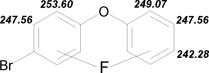
13C NMR spectra, see Table 2, show shifts to highest values on C1/1′ due to the -I effect of oxygen and on carbons with ipso-substitution, ranging from 154.0 – 163.7 ppm. The lowest shifts of 154.0 ppm (F-PBDE 3-2′F) and 154.3 ppm (F-PBDE 3-2F) were found in the ortho-positions C2/2′ due to electron density increasing on these positions by the influence of oxygen. Comparing the shifts induced by a meta-fluoro-substitution in C3/3′ shows the electron density increasing by ortho-bromo-substitution resulting in a lower shift of 159.7 ppm (F-PBDE 3-3F) versus 163.7 ppm (F-PBDE 3-3′F). The 1JCF couplings ranged from 242.28 Hz–253.60 Hz. The strength of the coupling is reflecting the strength of the C-F bond. The C2/2′ positions have the highest electron density based on 13C NMR shift assumption, and the 1JCF of the ortho-fluoro-substituents is the strongest, with 253.6 Hz (F-PBDE 3-2F) and 249.07 Hz (F-PBDE 3-2′F). Similar conclusions can be drawn based on electron density of the F-C bonds for 2JCF couplings. Aside from the electron density of the carbon, buttressing effects, electron donation and withdrawing over space; steric effects play a major role. To determine the change in electron density by fluoro-substitution, the difference between the 13C NMR shifts of a given substituted compound (F-PBDEs 3) and the corresponding parent compounds (PBDE 3) can be formed, see Fig. 4. Positive values indicate an increase of electron density, negative a decrease. This information is critical to understand shape and reactivity and is therefore of fundamental importance.
Fig. 4.

Changes in the 13C NMR shifts, δ [ppm], by fluorine substitution relative to PBDE 3 (4-bromodiphenyl ether). 13C NMR shifts indicate a change in electron density at the carbon atom. Positive values indicate increase of electron density, negative values an decrease. For more details see Experimental Section.
The 19F NMR spectra are of first order and can be explained on the basis of direct coupling with its neighboring hydrogens. The chemical shifts in 19F NMR are the highest for the positions C3, 5 and 4′ with −104.64 ppm, followed by C3′ and 5′ with −110.84 ppm, C2 and 6 with −128.05 ppm and finally C2 and 6′ with −130.68 ppm. This trend is in comparison with electron density of PBDE 3, determined by 13C NMR shifts. Aside the C4 (13C δ 115.8 ppm) what has due to the bromo-substituent the highest electron density, followed by C2′ and 6′ (13C δ 119.2 ppm), C2 and 6 (13C δ 120.6 ppm), C3′ and 5′ (13C δ 130.1 ppm), C3 and 5 (13C δ 132.9 ppm), see Table 2. The 19F NMR δ shift −119.55 ppm of C4′ can not be explained on the basis of electron density alone, since the 13C δ 123.9 ppm should result in a 19F δ around −125 ppm. We explain this anomaly on the basis of the anisotropy effect of the torsion energy, the so called ‘Ringstrom’. The JFH couplings are between 3JFH 8.0 Hz – 10.00 Hz, 4JFH 4.6 Hz – 8.4 Hz, 5JFH 1.1 Hz – 1.5 Hz and are by this very strong. F-PBDE 3-2′F showed a non-symmetrical specta. Since 1H-19F coupled spin systems can not lead to spectra of second or higher order, this observation can be explained on the basis of signal carryover and more than one signal coincidently resonate at the same frequency. The proton coupling partners are not magnetically equivalent.
The parent ion peak [M]+. is the main signal in MS for PBDE 3 and the corresponding F-PBDEs 3. Major fragments are [M-Br]+, [M-HBr]+., [M-C2Br]+., [M-C2H2Br]+. and [M-C2H4Br]+.. Fluorine loss is around 1% and refelects the strong C-F bond, especially in an aromatic system due to hyperconjugation. The [M]++ reflects the potential to stabilize a second positive charge of the molecule by delocalization or resonance. While for PBDE 3 the abundance of the [M]++ is only 1 %, it increases by a monofluorination to 14% (F-PBDE 3-2F), 16 % (F-PBDEs 3-3F, 3-3′F and 3-4′F) and even 24% (F-PBDE 3-2′F). A similar observation could be made comparing monofluorinated polycyclic aromatic hydrocarbons with their non-fluorinated parent compounds (Luthe et al., 2003). The electron density in the σ-bond-system diminishes by fluorosubstitution, but increases by hyperconjugation in the π-system since fluorine is too hard to retain the charge and pushes it back via p-π-orbital overlap. This results in a stabilization of the additional charge. Additionally, reinforced by the negative inductive effect of fluorine, the removal of a second electron should lead to a less energetic atomic orbital 1s22s22p4, with two unpaired electrons for fluorine.
4.3 C-F and C4-Br bond lengths
The differences in C-F and C-Br bond lengths may be explained on the basis of differences in electron density and orbital overlap. Many factors, e.g. mesomeric, inductive, steric and/or direct electric field effects, may alter the electron density. Substituent-induced chemical shifts in 13C NMR reflect the actual distribution of electron charges at the C atom between the carbon and the fluoro-substituent, see Fig. 4. The approach of 13C NMR measurements had been used previously (Luthe et al., 2007). Therefore, instead of using semi-empirical SFC-MO calculations, we have relied on substituent-induced chemical shifts and couplings. Fig. 4 gives an overview of the change of electron density for the C positions 1 to 6, and 1′ to 6′. Higher shift values indicate a reduction in electron density, lower ones increase at the carbon position. A lower electron density results in a less strong C-F bond and a lengthening of the bond. In the non substituted ring, C3′ has the highest 13C NMR shift δ of 130.1 ppm resulting in the longest C-F bond of 1.362 Å, followed by C4′ δ 123.9 ppm and C-F bond length 1.354 Å and C2′ δ 119.2 ppm and C-F bond length 1.347 Å. Comparing the shifts for C1′-C6′ in PBDE 3 with C1-C6 in diphenyl ether demonstrates that the bromine has a negligible effect on the non-bromo-substituted ring in PBDE 3. The following 13C NMR shifts, δ [ppm], in diphenyl ether were determined 156.9 (C1), 119.2 (C2, C6), 130.1 (C3, C5) and 123.9 (C4). The highest 13C NMR shift δ of 132.9 ppm results in the longest C-F bond of 1.357 Å at C3 position, followed by δ of 120.6 ppm results in the longest C-F bond of 1.349 Å at the C2 position. The strength of the JCF couplings does not follow the trend of the C-F bond lengths, see Fig. 5. We found in general that a strong coupling results in a shorter bond. But the values determined for the specific isomers do not reflect the trend of bond length. Aside from the electron density of the carbon, buttressing effects, electron donation and withdrawing over space; steric effects play a major role. By computation with SCF-MO the differences in the C-F bond lengths can not be determined.
Fig. 5.
Direct carbon-fluorine couplings, JCF [Hz] in all F-PBDEs 3. Stronger couplings relates to a higher electron density in the C-F bond.
There is a trend of C4-Br bond lengths. While the C-Br bond lengths of PBDE 3 and F-PBDEs 3-2F are 1.896(3) and 1.897(2)Å, for F-PBDEs 3-2′F, 3-3′F and 3-4′F (which do not carry the fluoro-substituent on the same ring as the bromo-substituent), the C-Br bond increases to 1.903(2), 1.904(2) and 1.897(3)Å. The shortest C-Br bond length with 1.880(3)Å are determined in the vicinal position in F-PBDE 3-3F. This can not be explained on the basis of electron density determined by 13C NMR measured in PBDE 3. The C4-Br bond lengths result from the additive influences of fluoro- and bromo-substituents. Therefore we determine the change of electron density in the F-PBDEs 3 at the various positions by comparing the 13C NMR shifts of the F-PBDEs 3 with the corresponding PBDE 3, see Fig. 4. The vicinal fluoro-substituent in F-PBDE 3-3F results in the highest electron increase in the C4 position of Δδ 13.7 ppm by ortho-induction, giving the shortest C4-Br bond lengths of 1.880(3)Å. On the other hand, the strongest reduction of electron density by fluorine substitution at C4 was determined to be Δδ −0.9 ppm for F-PBDE 3-3′F, resulting in the longest C4-Br bond with 1.904(2)Å. Again, the differences in the C4-Br bond lengths can not be determined by computation with SCF-M.
4.4 Influence of fluoro-substitution on aromatic interior bond angles
All three, X-ray analysis, microwave spectroscopy and SCF-MO computation show a distorted ring in fluorobenzene. As discussed earlier (Luthe et al., 2007), this is caused by hyperconjugation of the 2p orbitals of the fluoro substituent with the aromatic π system. In chloro- and bromobenzene this effect was not be observed, since the 3p and 4p orbitals are too big to result in a good overlap with the aromatic π system. The fluoro-ipso-bond angle is widened to 122.9(2)° (F-PBDE 3-3F) and the aligned angles are narrowed down to 117.75(13)° and 117.9(2)° (F-PBDE 3-2F, 3-3F). The other angles are just slightly affected and show the common angles of 120.2°. This observation could be partly computed. The broadening of the interior angle at the ipso-substitution can simulated with a lower amplitude, but the narrowing is averaged over all other angles, which is not correct. In our study of F-PCBs (Luthe et al., 2007a), we could observe an attration of the fluoro to the chloro substituent in F-PCB 3-3F. This appeared on the surface to be very unusual, since one might expect that chloro and fluoro substituents should display repulsive behavior towards each other. If the chlorine functions as an electron donor for the more electronegative electron acceptor fluorine, this would create a vicinal coupling through space. However, this was not the case with the bromo-substituent in F-PBDE 3-3F. We explain this on the basis that the overlap of the 2p and the 4p orbitals of the fluoro- and the bromo- are much less due to their different size. A more detailed study regarding this aspect is in progress.
4.5 Influence of fluoro-substitution on the torsion angles
We compared the torsion C1′-O-C1-C6(2) and C2′(6′)-C1′-O-C1 and the bond C1-O-C1′ angles in diphenyl ether affected by fluoro-, chloro-, bromo- and methyl- and no substitutents in the ortho-positions, see Table 5. There we observed that in general there is a trend of alignment of computed and determined data. The strength depends on the size of the substituent, grade of substitution and the position. So there is a comparison for the torsion angles of methyldiphenyl ether (determined: 145.48°, −36.23°; computed: 141.3°, −42.1°) dibromodiphenyl ether (determined: 78.70°, −107.05°; computed: 92.1°, 92.1°) and dimethyl ether (determined: 93.08°, −91.22°; computed: 91.9°, 91.9°) with ortho-substitutions on one ring, but not with the one on two rings. With four fluoro-substituents in ortho-positions the fit of computed and determined torsion angles is in alignment (determined: 57.71°, −127.97°; computed: 49.4°, −134.2°). Since the average distance of the ether linkage is 2.76 Å, compared with 1.48 Å in PCBs (Luthe et al., 2007a) the steric interaction of the ortho-substituents is much weaker. Both, the ether bond and the angle of the C1-O-C1′ bond attribute high flexibility to the substituted diphenyl ethers minimizing the steric interaction. Therefore the interaction must be strong enough by size of the substituent, grade and pattern of substitution to emphasise the intramolecular interaction versus energy gaining by week intermolecular interactions in solid state, e.g. stacking effects and C-H(F, Br) …π interactions. Therefore the computed values, calculated under ideal circumstances in the vacuum, differ strongly from the ones determined by X-ray for small substituents and low grade of substitution. We observed this effect as well in our series of F-PBDEs 3 and PBDE 3, where the computed and determined torsion and ether bond angles differ strongly. The steric interaction is too weak in solid state for this series to give a clear picture of the intramolecular interactions. Even that the intermolecular interactions of PBDE 3 and the F-PBDE 3 isomers are weak and only dominated by C-H(F,Br) ····π and C-H····F interactions. The interpretation of X-ray data for receptor activity of PBDEs as shown in Table 1 should be evaluated carefully against this finding and it is advisable to use computed data comprehensive for these studies. This result might be contribute to the scientific discussion around the AhR activity of PBDEs or PBDF impurities from a QSAR point of view.
4.6 Packing of the F-PBDEs 3 isomers
The intermolecular interactions for PBDE 3 and all five F-PBDE 3 isomers were dominated by weak C-H(F,Br) ····π and C-H····F interactions, whereas the F-PCBs 3 were dominated by π ···π stackings. This leads to crystal packings built up by columns which are interconnected via C-H····π interactions, C-H····F(Br) close contacts and van der Waals forces. The F-PBDEs 3-3′F and 3-4′F have very similar crystal packing interactions. The F-PBDE 3-2F isomer connects stacks into bi-layers with the F-atoms on the ‘exterior’ of the bi-layers.. There are no linear halo ··· halo interactions, e.g. F····Br, as could be found for the F····Cl in F-PCBs. This is due to the big difference of the orbital sizes.
Fig. 3.


Stereo diagrams of unit cell contents showing intermolecular interactions (dotted lines). Atoms are shown as spheres of arbitrary size with the highest atomic number having the largest radius and the lowest the smallest. a) 2-fluoro-4-bromodiphenyl ether (3-2F), b) 2′-fluoro-4-bromodiphenyl ether (3-2′F), c) 3-fluoro-4-bromodiphenyl ether (3-3F), d) 3′-fluoro-4-bromodiphenyl ether (3-3′F), e) 4′-fluoro-4-bromodiphenyl ether (3-4′F) and f) 4-bromodiphenyl ether (PBDE 3).
Acknowledgments
We would like to acknowledge Gerd-V. Röschenthaler, University Bremen, Germany, Udo A. Th. Brinkman and Freek Ariese, both of Free University, Amsterdam, The Netherlands, Jan Scharp and Michiel van Buchem, both of Saxion University, Enschede, The Netherlands, for stimulating discussions and Santhana M. Velupillai for support with the NMR interpretation and Iza Korwel for support with GC-MS. This work was financially supported by the Alexander von Humboldt Foundation, Bonn, Germany, and National Institute of Environmental Health Sciences grant P42 ES013661.
References
- Allchin CR, Law RJ, Morris S. Environ Pollut. 1999;105:197–207. [Google Scholar]
- Allen FH. Acta Cryst. 2002;B58:380–388. doi: 10.1107/s0108768102003890. [DOI] [PubMed] [Google Scholar]
- Ariyoshi N, Iwasaki M, Kato H, Tsusaki S, Hamamura M, Ichiki T, Oguri K. Environmental Toxicology and Pharmacology. 1998;5:219–225. doi: 10.1016/s1382-6689(98)00007-6. [DOI] [PubMed] [Google Scholar]
- Ballschmiter KZ, Zell M. Fresenius Z anal Chem. 1980;302:20–31. [Google Scholar]
- Bergman Å, Athanasiadou M, Wehler EK, Sjödin A. Organohalogen Compounds. 1999;43:89–92. [Google Scholar]
- Bromine Science and Environmental Forum. Total Market Demand. 2003 available at: www.bsef.com.
- Carlson GP. Toxicol Lett. 1980;5:19–25. doi: 10.1016/0378-4274(80)90143-5. [DOI] [PubMed] [Google Scholar]
- Ceccatelli R, Faass O, Schlumpf M, Lichtensteiger W. Toxicology. 2006;220:104–116. doi: 10.1016/j.tox.2005.12.004. [DOI] [PubMed] [Google Scholar]
- Chen G, Bunce NJ. Toxicol Sci. 2003;76:310–320. doi: 10.1093/toxsci/kfg236. [DOI] [PubMed] [Google Scholar]
- Chouteau F, Ramanitrahasimbola D, Rasoanaivob P, Chibale K. Bioorganic & Medicinal Chemistry Letters. 2005;15:3024–3028. doi: 10.1016/j.bmcl.2005.04.033. [DOI] [PubMed] [Google Scholar]
- Cristau H-J, Cellier PP, Hamada S, Spindler J-F, Taillefer M. Organic Letters. 2003;6:913–916. doi: 10.1021/ol036290g. [DOI] [PubMed] [Google Scholar]
- Darnerud PO, Eriksen GS, Jóhannesson T, Larsen PB, Viluksela M. Polybrominated diphenyl ethers: occurrence, dietary exposure, and toxicology. Environ Health Perspect. 2001;109:49–68. doi: 10.1289/ehp.01109s149. [DOI] [PMC free article] [PubMed] [Google Scholar]
- de Boer J, Wester PG, van der Horst A, Leonards PEG. Polybrominated diphenyl ethers in influents, suspended particulate matter, sediments, sewage treatment plant and effluents and biota from the Netherlands. Environ Pollut. 2003;122:63–74. doi: 10.1016/s0269-7491(02)00280-4. [DOI] [PubMed] [Google Scholar]
- Dewar MJS, Zoebisch EG, Healy EF, Stewart JJP. AM1: a new general purpose quantum mechanical molecular model. J Am Chem Soc. 1985;107:3902–3909. [Google Scholar]
- Eljarrat E, Barcelo D. Sample handling and analysis of brominated flame retardants in soil and sludge samples. Trends in Analytical Chemistry. 2004;23:727–736. [Google Scholar]
- Environmental Health Criteria. Brominated dipheynyl ethers. Vol. 162. World Health Organization; 1994. [Google Scholar]
- Eslami B, Koizumi A, Ohta S, et al. Chemosphere. 2006;63:554–561. doi: 10.1016/j.chemosphere.2005.09.067. [DOI] [PubMed] [Google Scholar]
- Germer S, Fery Y, van der Ven L, Piersma AH, Kamyschnikow A, Schrenk D. Toxicol Lett. 2006;164S:S159–160. doi: 10.1016/j.tox.2005.10.019. [DOI] [PubMed] [Google Scholar]
- Gouin T, Thomas GO, Cousins I, Barber J, Mackay D, Jones KC. Environ Sci Technol. 2002;36:1426–1434. doi: 10.1021/es011105k. [DOI] [PubMed] [Google Scholar]
- Hale RC, La Guardia MJ, Harvey E, Mainor M. Chemosphere. 2002;46:729–735. doi: 10.1016/s0045-6535(01)00237-5. [DOI] [PubMed] [Google Scholar]
- Hallgren S, Darnerud PO. Toxicology. 2002;177:227–243. doi: 10.1016/s0300-483x(02)00222-6. [DOI] [PubMed] [Google Scholar]
- Harner T, Ikonomou M, Shoeib M, Stern G, Diamond M. Organohalogen Compd. 2002;57:33–36. [Google Scholar]
- Hites RA, Foran JA, Schwager SJ, Knuth BA, Hamilton MC, Carpenter DO. Global Assessment of Polybrominated Diphenyl Ethers in Farmed and Wild Salmon. Environ Sci Technol. 2005;39:379–380. doi: 10.1021/es049548m. [DOI] [PubMed] [Google Scholar]
- Hites R. Polybrominated diphenyl ethers in the environment and in people: A meta-analysis of concentrations. Environ Sci Technol. 2004;38:945–956. doi: 10.1021/es035082g. [DOI] [PubMed] [Google Scholar]
- Hoh E, Hites RA. Brominated Flame Retardants in the Atmosphere of the East-Central United States. Environ Sci Technol. 2005;39:7794–7802. doi: 10.1021/es050718k. [DOI] [PubMed] [Google Scholar]
- Hooper K, McDonald TA. Environ Health Perspect. 2000;108:387–392. doi: 10.1289/ehp.00108387. [DOI] [PMC free article] [PubMed] [Google Scholar]
- Hooper K, She J. Lessons from the Polybrominated Diphenyl Ethers (PBDEs): Precautionary Principle, Primary Prevention, and the Value of Community-Based Body-Burden Monitoring Using Breast Milk. Environmental Health Perspectives. 2003;111:109–114. doi: 10.1289/ehp.5438. [DOI] [PMC free article] [PubMed] [Google Scholar]
- Hu J, Eriksson L, Bergman Å, Kolehmainen E, Knuutinen J, Suontamo R, Wei X. Molecular orbital studies on brominated diphenyl ethers. Part I: conformational properties. Chemosphere. 2005;59:1033–1041. doi: 10.1016/j.chemosphere.2004.11.028. [DOI] [PubMed] [Google Scholar]
- Ikonomou MG, Rayne S, Addison RF. Environ Sci Technol. 2002b;36:1886–1892. doi: 10.1021/es011401x. [DOI] [PubMed] [Google Scholar]
- Ikonomou MG, Rayne S, Fischer M, Fernandez MP, Cretney W. Chemosphere. 2002a;46:649–663. doi: 10.1016/s0045-6535(01)00229-6. [DOI] [PubMed] [Google Scholar]
- Johanson-Restrepo B, Kannan K, Raport DP. Polybrominated Diphenyl Ethers and Polychlorinated Biphenyls in Human Adipose Tissue from New York. Environ Sci Technol. 2005;39:5177–5182. doi: 10.1021/es050399x. [DOI] [PubMed] [Google Scholar]
- Johansson M, Nilsson S, Lund BO. Environ Health Perspect. 1998;106:769–772. doi: 10.1289/ehp.98106769. [DOI] [PMC free article] [PubMed] [Google Scholar]
- Kretschmer XC, Baldwin WS. Chem Bio Interac. 2005;155:111–128. doi: 10.1016/j.cbi.2005.06.003. [DOI] [PubMed] [Google Scholar]
- Kuiper RV, Bergman A, Vos JG, van den Berg M. Aquatic Toxicology. 2004;68:129–139. doi: 10.1016/j.aquatox.2004.03.005. [DOI] [PubMed] [Google Scholar]
- Lind Y, Aune M, Atuma S, Becker W, Bjerselius R, Glynn A, Darnerud PO. Food Intake of the Brominated Flame Retardants: PBDE’s and HBCD in Sweden. Organohalogen Compounds. 2002;58:181–184. [Google Scholar]
- Luthe G, Ariese F, Brinkman UATh. Monofluorinated Polycyclic Aromatic Hydrocarbons: Standards in environmental Chemistry and Biochemical Applications. In: Neilson AH, editor. Handbook of Environmental Chemistry: Organic Fluorine Compounds. Springer Verlag; Berlin, Germany: 2002. pp. 249–275. [Google Scholar]
- Luthe G, Leonards PE, Reijerink GS, Liu H, Johansen JE, Robertson LW. Environ Sci Technol. 2006a;40:3023–29. doi: 10.1021/es052410z. [DOI] [PubMed] [Google Scholar]
- Luthe G, Schut BG, Aaseng JE, Johansen JE. Chemosphere. 2006b doi: 10.1016/j.chemosphere.2006.02.029. in press. [DOI] [PubMed] [Google Scholar]
- Luthe G, Ramos L, Dalluege J, Brinkman UATh. Chromatographia. 2003;57:379–384. [Google Scholar]
- Luthe G, Swenson DC, Robertson LW. Acta Crystallographica B. 2007a;B63:319–327. doi: 10.1107/S0108768106054255. [DOI] [PubMed] [Google Scholar]
- Luthe G, Jacobus J, Robertson LW. Environ Toxicol Pharmacol. 2007b doi: 10.1016/j.etap.2007.10.017. submitted. [DOI] [PMC free article] [PubMed] [Google Scholar]
- Marsh G, Hu J, Jakobsson E, Rahm S, Bergman Å. Environmental Science and Technology. 1999;33:3033–3037. [Google Scholar]
- Marsh G, Stenutz R, Bergman Å. European Journal of Organic Chemistry. 2003;14:2566–2576. [Google Scholar]
- Mazdai A, Dodder NG, Abernathy MP, Hites RA, Bigsby RM. Polybrominated diphenyl ethers in maternal and fetal blood samples. Environ Health Perspec. 2003;111:1249–1252. doi: 10.1289/ehp.6146. [DOI] [PMC free article] [PubMed] [Google Scholar]
- Meironyte D, Noren K, Bergman A. Analysis of polybrominated diphenyl ethers in Swedish human milk. A time-related trend study. J Toxicol Environ Health A. 1999;58:329–41. doi: 10.1080/009841099157197. [DOI] [PubMed] [Google Scholar]
- Meerts IATM, Letcher RJ, Hoving S, Marsh G, Bergman A, Lemmen JG, van der Burg B, Brouwer A. Environ Health Perspect. 2001;109:399–407. doi: 10.1289/ehp.01109399. [DOI] [PMC free article] [PubMed] [Google Scholar]
- Nevalainen T, Rissanen K. AM1 and single-crystal X-ray diffraction study of the conformational properties of chlorinated diphenyl ethers. J Chem Soc, Perkin Trans. 1994;2:271–279. [Google Scholar]
- Nordic Council of Ministers. Report from an NNT project group. TemaNord; Copenhagen, Denmark: 1998. Polybrominated Diphenyl Ethers: Food Contamination and Potential Risks; p. 503. [Google Scholar]
- Ojima I, McCarthy JR, Welch JT. ACS Symp Ser. Vol. 639. American Chemical Society; Washington DC, USA: 1996. Biochemical Frontiers of Fluorine Chemistry. [Google Scholar]
- Qian D-Q, Shine HJ, Thurston JH, Whitmire KH. Journal of Physical Organic Chemistry. 2003;16:142–147. [Google Scholar]
- Pessah IN, Hansen IG, Alberson Te, Garner CE, Ta TA, Do Z, Kim KH, wong PW. Chem Re Toxicol. 2006;19:92–101. doi: 10.1021/tx050196m. [DOI] [PubMed] [Google Scholar]
- Peters AK, Nijmeijer S, Gradin K, Backlung M, Bergman A, Poellinger L, Denison Ms, van den Berg M. Tocicol Sci. 2006;91:133–142. doi: 10.1093/toxsci/kfj186. [DOI] [PMC free article] [PubMed] [Google Scholar]
- Peters AK, Sanderson JT, Bergman A, van den Berg M. Tocicol Lett. 164:123–132. doi: 10.1016/j.toxlet.2005.12.002. [DOI] [PubMed] [Google Scholar]
- Qian DQ, Shine HJ, Thurston JH, Whitmire KH. Journal of Physical Organic Chemistry. 2003;16:142–147. [Google Scholar]
- Ryan JJ, Patry B. Determination of brominated diphenyl ethers (BDE’s) and levels in Canadian human milks. Organohalogen Compounds. 2000;47:57–60. [Google Scholar]
- Sander JM, Burka LT, smith CS, Black W, James R, Cunningham ML. Toxicol Sci. 2005;88:127–133. doi: 10.1093/toxsci/kfi288. [DOI] [PubMed] [Google Scholar]
- Schaefer T, Penner GH, Takeuchi C, Tseki P. Remarks on the internal motion in diphenyl ether. Fluorodiphenylethers. Can J Chem. 1988;66:1647–1650. [Google Scholar]
- Sellström U, Kierkegaard A, de Wit C, Jansson B. Environ Toxicol Chem. 1998;17:1065–1072. [Google Scholar]
- Sjödin A, Carlsson H, Thursesson K, Sjolin S, Bergman A, Ostman C. Environ Sci Technol. 2001;35:448–454. doi: 10.1021/es000077n. [DOI] [PubMed] [Google Scholar]
- Strandberg B, Dodder NG, Basu I, Hites RA. Environ Sci Technol. 2001;35:1078–1083. doi: 10.1021/es001819f. [DOI] [PubMed] [Google Scholar]
- Stoker TE, Cooper RL, Lambright VS, Wilson VS, Furr J, Gray LE. Toxcicol Appl Pharm. 2005;207:78–88. doi: 10.1016/j.taap.2005.05.010. [DOI] [PubMed] [Google Scholar]
- Stoker TE, Laws SC, Crofton KM, Hedge JM, Ferrell JM, Cooper RL. Toxicol Sci. 2004;78:144–155. doi: 10.1093/toxsci/kfh029. [DOI] [PubMed] [Google Scholar]
- ter Schure AFH, Larsson P, Merilä J, Jönsson KI. Environ Sci Technol. 2002;36:5057–5061. doi: 10.1021/es0258632. [DOI] [PubMed] [Google Scholar]
- Tsushima T, Kawada K, Tsuji T. Tetrahedron Lett. 1982;23:165–168. [Google Scholar]
- Wang Y, Zhao C, Ma W, Liu H, Wang T, Jiang G. Chemosphere. 64:515–524. doi: 10.1016/j.chemosphere.2005.11.061. [DOI] [PubMed] [Google Scholar]
- Welch JT, Eswarakrishnan S. Fluorine in Bioorganic Chemistry. John Wiley; New York, NY, USA: 1991. [Google Scholar]
- Zeller T. New York Times. 2006. Dec 18, p. 3. [Google Scholar]
- Zhou T, Taylor MM, DeVito MJ, Crofton KM. Toxicol Sci. 2002;66:105–116. doi: 10.1093/toxsci/66.1.105. [DOI] [PubMed] [Google Scholar]
- Zhu LY, Hites RA. Brominated Flame Retardants in Sediment Cores from lakes Michigan and Erie. Environ Sci Technol. 2005;39:5904–5904. doi: 10.1021/es048240s. [DOI] [PubMed] [Google Scholar]