Abstract
The separation of particles from a heterogeneous mixture is critical in chemical and biological analyses. Many methods have been developed to separate particles in microfluidic devices. However, the majority of these separations have been limited to be size based and binary. We demonstrate herein a continuous dc electric field driven separation of carboxyl-coated and noncoated 10 μm polystyrene beads by charge in a double-spiral microchannel. This method exploits the inherent electric field gradients formed within the channel turns to manipulate particles by dielectrophoresis and is thus termed curvature-induced dielectrophoresis. The spiral microchannel is also demonstrated to continuously sort noncoated 5 μm beads, noncoated 10 μm beads, and carboxyl-coated 10 μm beads into different collecting wells by charge and size simultaneously. The observed particle separation processes in different situations are all predicted with reasonable agreements by a numerical model. This curvature-induced dielectrophoresis technique eliminates the in-channel microelectrodes and obstacles that are required in traditional electrode- and insulator-based dielectrophoresis devices. It may potentially be used to separate multiple particle targets by intrinsic properties for lab-on-a-chip applications.
INTRODUCTION
The separation of particles (both synthetic and biological) from a heterogeneous mixture is critical in chemical and biological analyses. To date, many methods have been developed to separate and sort particles in microfluidic devices, which take place in either a batchwise or continuous-flow manner.1, 2, 3 The former type typically includes filtration,4 chromatography,5 electrophoresis,6 and field-flow fractionation.7 Continuous-flow separation can be driven by either an externally imposed (i.e., active) or an internally induced (i.e., passive) force field.8, 9, 10 In the active mode an external gravitational,11 electrical,12 optical,13 magnetic,14 acoustic,15 or hydrodynamic16, 17 force field acts on the aligned particles at an angle to the flow direction and deflects them to different flow paths based mostly on particle size for a continuous sorting. For this to happen, however, additional force(s) is usually required to actuate the particulate solution and align the suspended particles. The passive methods utilize the channel topology-induced force to manipulate particles to differential equilibrium positions during the travel, among which hydrodynamic filtration,18 hydrophoresis,19 and inertia20, 21, 22 based continuous separations have been demonstrated. However, these methods are basically capable of separating particles by size only.
Dielectrophoresis (DEP) is another powerful tool for separating and sorting particles by size or polarizability (determined by the electric conductivity and permittivity of the particle and suspending medium as well as the ac field frequency23) in microfluidic systems.24, 25, 26, 27 It has been realized mainly by using electrode-28, 29 and insulator-based30, 31, 32 approaches. In electrode-based dielectrophoresis (eDEP) devices, high-frequency ac electric voltages are imposed upon pair(s) of microelectrodes placed inside a microchannel to create electric field gradients for particle DEP.33, 34, 35, 36, 37, 38, 39, 40, 41, 42, 43, 44 The fabrication complexity and surface fouling of the in-channel microelectrodes are still the main concerns in eDEP devices. These two issues do not occur in another form of eDEP, named as contactless DEP (cDEP) by the authors,45, 46 in which the electrodes are physically isolated from the sample. However, the typically 1 MHz level ac field frequency of state-of-the-art amplifiers significantly limits the application of this separation technique. Moreover, a pressure-driven pumping of the particle solution is necessary in all eDEP devices in order for continuous operation.
Insulator-based dielectrophoresis (iDEP) eliminates the above difficulties accompanying eDEP by using insulating hurdles, posts, and ridges to locally squeeze the electric current passage and generate the nonuniform electric field.47, 48, 49, 50, 51, 52, 53, 54, 55, 56, 57 These micro-obstacles are made of the same material as the microchannel substrate itself, which significantly simplifies the fabrication process. Moreover, both dc and dc-biased ac (of any frequency) electric voltages can be applied to the electrodes positioned in end-channel reservoirs, and so the pressure-driven pumping of particle solutions becomes unnecessary. However, the in-channel obstacles may cause negative effects on the sample (especially to bioparticles) and the device as well due to, for example, the potential Joule heating and particle clogging issues.58, 59, 60 In addition, electric field gradients can also be generated in the transition zone between a leading and a trailing electrolyte due to the mismatch of electric conductivity. The resulting dielectrophoretic force and others as well have been demonstrated to implement an “isotachophoretic” trapping and separation of particles.61
Recently, our group has developed a new approach to separating particles in serpentine or spiral microchannels by the use of curvature-induced dielectrophoresis,61, 62, 63, 64 which is essentially a new form of iDEP. This method exploits the inherent electric field gradients formed within microchannel turns to manipulate particles by DEP.65 As such, the adverse effects caused by the micro-obstacles in iDEP devices are mitigated. We found that in an appropriate suspending medium large particles experience negative DEP in a serpentine microchannel and migrate toward the channel center plane while small particles undergo positive DEP and line the channel sidewalls. These distinctive focusing phenomena were combined to implement a continuous separation of particles by size.66 In another study, we utilized the negative DEP in a serpentine microchannel to push small particles to the channel center and meanwhile bounce large particles between the two sidewalls for a continuous sorting.67 Additionally we demonstrated a continuous binary separation of particles by size in a double-spiral microchannel, where particles are focused by negative DEP to a stream flowing near the outer wall of the first spiral and then deflected by negative DEP to size-dependent flow paths in the second spiral.68
As reviewed above, however, the majority of the particle separations demonstrated so far in microfluidic systems have been limited to be size based and binary.1, 2, 3, 8, 9, 10 In this work we demonstrate that curvature-induced DEP can also be exploited to separate particles by surface charge in a double-spiral microchannel. Moreover, we use this DEP method to implement a continuous ternary separation of particles by charge and size at the same time. Additionally, a numerical model is developed to simulate the observed particle separation processes in spiral microchannels.
EXPERIMENT
Microchannel fabrication
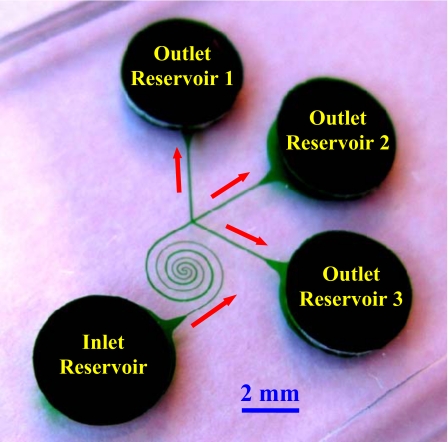
The microchannel was fabricated with poly(dimethylsiloxane) (PDMS) using the standard soft lithography technique. The detailed procedure is given elsewhere.54 As shown in Fig. 1, the channel is composed of two spirals that have three loops in each and are asymmetric in structure. The first spiral is uniformly 50 μm wide and connected to the inlet reservoir (see the labels in Fig. 1) through a short straight segment of equal width. It circulates counterclockwise up to the channel center and measures about 13 mm long. The second spiral starts at the channel center and extends clockwise with a gradually increasing width from 50 to 100 μm. It is followed by a 1.5-mm-long straight segment, which trifurcates into three equal branches of 100 μm width prior to ending at the outlet reservoirs 1–3 (see the labels in Fig. 1). The diameter of the innermost semicircle is 100 μm for both spirals. The radial distance between neighboring loops increases from the inner 150 μm to the outer 350 μm in order to avoid the electrical leakage through the PDMS wall.69 The channel is 25 μm deep everywhere and measures 39 mm long in total with an overall footprint of less than 2×2 cm2 including all the reservoirs.
Figure 1.
Picture of the asymmetric double-spiral microchannel. The block arrows indicate the flow directions during the process of particle separation.
Particle solution preparation
In demonstrating the particle separation by charge, plain noncoated polystyrene beads of 10(±0.2) μm in diameter (Sigma-Aldrich) and fluorescent carboxyl-coated polystyrene beads of 10.14(±1.04) μm in diameter (Bangs Laboratories) were mixed and resuspended in 1 mM phosphate buffer at a concentration of about 107 particles∕ml for each type. In the experiment of particle separation by charge and size, plain noncoated polystyrene beads of 5(±0.1) μm in diameter (Sigma-Aldrich) were added to the above particle mixture, which was then resuspended in 0.1 mM phosphate buffer to a concentration of 107–108 particles∕ml for each type. Tween 20 (0.5% v∕v, Fisher Scientific) was added to both of these particle solutions to suppress particle adhesions to channel walls as well as particle aggregations. Moreover, particle solution was stirred before being introduced to the inlet reservoir.
Particle manipulation and visualization
Electric voltages were supplied by a dc power supply (Glassman High Voltage, High Bridge, NJ) in conjunction with a custom-made voltage controller. Pressure-driven flow was eliminated by carefully balancing the liquid heights in the reservoirs prior to every experiment. Particle motion was monitored using an inverted microscope (Nikon Eclipse TE2000U, Nikon Instruments, Lewisville, TX), through which videos and images at the inlet, center, and outlet regions of the spiral microchannel were recorded using a charge-coupled device camera (Nikon DS-Qi1Mc). The captured digital videos and images were processed using the Nikon imaging software (NIS-ELEMENTS AR 2.30). The trajectories of plain and fluorescent beads were obtained by superimposing sequential images in the Nikon imaging software with reference to a dark and bright background, respectively. They were then combined in MATLAB® to achieve the graphical demonstration of particle separation in terms of discrete particle trajectories.
THEORY
Curvature-induced DEP for particle deflection
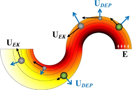
Figure 2 shows the streamlines (short arrows indicate the directions) and contour (represented by the background color, the darker the higher) of electric field, E, in the center region of the spiral microchannel. Only the first half-loop is included for each spiral, and the width change in the second spiral is exaggerated for a better demonstration. In both spirals, electric field reaches the maximum and minimum values at the inner and outer walls, respectively, due to the variation in path length for electric current. Therefore, particles experience a transverse dielectrophoretic motion, UDEP, when they follow the electric field lines to move electrokinetically through the curving channel with velocity, UEK (see Fig. 2). Using the effective dipole moment method,70 one can obtain68
| (1) |
| (2) |
where μDEP is the dielectrophoretic mobility of particles, E is the electric field with a magnitude of E, R is the radius of the local curvature of an electric field line (equivalent to a streamline in pure electrokinetic flows,71 see Fig. 2), is the unit normal vector of the streamline, εf is the permittivity of the suspending fluid, d is the particles diameter, fCM the so-called Clausius–Mossotti (CM) factor,70, 72 and μf is the fluid viscosity.
Figure 2.
Illustration of curvature-induced DEP for particle (represented by spheres) focusing and separation in an asymmetric double-spiral microchannel. Also illustrated are the electric field lines (short arrows indicate the directions) and the contour of electric field magnitude (background, the darker the higher).
The dielectrophoretic particle deflection across the channel width can be approximately characterized as
| (3) |
where μEK is the electrokinetic mobility of particles, and θ is the rotating angle of the spiral channel in one direction. It is straightforward that increasing the electric field and∕or employing multiple loops (each loop has a rotating angle of 2π) for the spiral enhance the particle deflection. More importantly, this deflection is a function of particle mobility ratio, which in dc electric fields is given by66, 67, 68
| (4) |
| (5) |
where ζp is the zeta potential (a measure of surface charge) of particles, ζw is the average zeta potential of the channel wall, σp is the electric conductivity of particles, and σf is the electric conductivity of the suspending fluid. The dependence of deflection on the intrinsic properties of particles including diameter, charge, and conductivity enables the continuous separation of particles by one or a combination of these properties in spiral microchannels, which will be explained below.
Curvature-induced DEP for particle focusing and separation
Traditionally, a negative fCM indicates negative DEP which displaces particles to the region of a lower electric field.23 Since polystyrene beads73 and biological cells74 appear poorly conducting in dc electric fields, they experience negative DEP in typical buffer solutions due to σp<σf and thus migrate toward the outer channel wall in each spiral as illustrated in Fig. 2. Therefore, we can use curvature-induced DEP to focus all particles to a stream flowing near the outer wall of the first spiral if the electric field, E, and∕or the number of loops in the first spiral, reflected by θ in Eq. 3, are sufficiently large. The minimum value of the product Eθ for such dielectrophoretic focusing is determined by the particle with the smaller (or the smallest if more than two types of particles are present in the mixture) mobility ratio, (μDEP∕μEK)small.
When the focused particle stream flows into the second spiral with electric field magnitude∕gradients being lower than in the first spiral (see Fig. 2), those particles with mobility ratios larger than (μDEP∕μEK)small can still be displaced by DEP to near the outer channel wall as they actually attain an overfocusing in the first spiral. In contrast, the smaller (or the smallest) particles with (μDEP∕μEK)small are deflected at a lower rate and thus by a smaller distance though still toward the outer wall of the second spiral. As a result, particles with dissimilar mobility ratios, μDEP∕μEK, can be continuously separated by DEP in the second spiral and eventually sorted into the three outlet reservoirs 1–3 after passing the channel trifurcation (see Fig. 1). According to Eq. 4, this method can apply to the separation of particles by size, charge, and∕or conductivity, among which a binary separation of polystyrene beads by size has been recently demonstrated by the authors.68
Numerical modeling
We developed a two-dimensional (2D) numerical model to simulate the electrokinetic particle separation in spiral microchannels through curvature-induced DEP. This model is revised from that developed by Kang et al.75 and has been validated by several experiments from our group.54, 62, 63, 64, 66, 67, 76 It neglects the perturbations of a particle to the flow and electric fields and employs a correction factor c to account for the effects of the particle size (and others such as particle-particle interactions) on the dielectrophoretic velocity. Hence, the velocity of the particle is written as
| (6) |
| (7) |
where the three terms on the right-hand-side of Eq. 6 represent the particle velocities due to electrokinetic flow, DEP, and particle-wall interactions, fp−w is the coefficient characterizing the wall-induced particle velocity as a function of the particle-wall separation distance γ,75 and is the local unit vector normal to the channel wall. The last velocity due to the particle-wall interactions has been experimentally demonstrated by our group in particle electrophoresis through a straight microchannel.77, 78 Note that the inertial and centrifugal motions have been neglected in Eq. 6 because the Reynolds and Dean numbers are both very small under the experimental conditions. The instantaneous position of a particle, xp, is obtained by integrating the particle velocity Up, i.e.,
| (8) |
where x0 represents the initial location of the particle, and t is the time period from the initiation.
The numerical modeling was performed in COMSOL® (Burlington, MA) with the MATLAB® interface. A 2D model of the serpentine microchannel was first developed in COMSOL®, where the effects of the top and bottom channel walls on particle motions were neglected.49, 53, 54, 62, 63, 64, 66, 67, 75, 76 Then, the electric field distribution was solved from Laplace equation in COMSOL®. The boundary conditions include the electric voltages imposed to the reservoirs and the insulating condition on all channel walls. Next, the finite-element-model (FEM) structure was exported into MATLAB® to determine the trajectory of a particle whose initial position was specified at the channel entrance. A custom-written program in MATLAB® was used to determine the particle position xp, where the key function is to calculate the particle-wall separation distance γ and thus the coefficient fp−w from Eq. 7. All particles were assumed to enter into the spiral microchannel uniformly from the inlet reservoir. Five particles were picked for each type with their initial positions evenly distributed at the entrance of the spiral channel.
Other parameters required in the modeling were obtained as follows. The electrokinetic mobility, μEK, was determined by tracking the motions of individual particles in a straight channel where DEP is negligible. The dielectrophoretic mobility, μDEP, was calculated from Eq. 2 with the typical dynamic viscosity, μ=1.0×10⁻³ kg∕m s and permittivity εf=6.9×10⁻¹⁰ C∕V m for pure water at 20 °C. The electric conductivity of particles with a diameter d was determined using σp=4Ks∕d with Ks=1 nS being the surface conductance recommended by Ermolina and Morgan.73 The electric conductivities of 1 and 0.1 mM phosphate buffers measured 210 and 26 μS∕cm, respectively. The correction factor for dielectrophoretic velocity, c, was determined by fitting the predicted particle trajectories to the experimentally observed pathlines.
RESULTS AND DISCUSSION
Binary separation of particles by charge
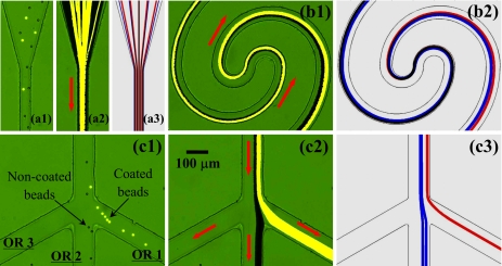
Figure 3 shows the continuous binary separation of plain noncoated (dark) and fluorescent carboxyl-coated (bright) 10 μm polystyrene beads in the spiral microchannel using curvature-induced DEP. The beads were resuspended in 1 mM phosphate buffer. The inlet reservoir was imposed a 400 V dc voltage while the three outlet reservoirs were all grounded (see Fig. 1). The average electric field in the 50 μm wide first spiral is about 160 V∕cm as obtained from the numerical simulation. The electric field in the second spiral is lower than this value since its width increases from 50 to 100 μm. The measured values of electrokinetic mobility, μEK, are 3.3×10⁻⁸ and 1.6×10⁻⁸ m2∕V s for the noncoated and coated beads, respectively, indicating their dissimilar surface charges, i.e., ζp in Eq. 4. As they are of nearly identical sizes and made of the same material, the two types of beads are expected to experience similar DEP or possess similar dielectrophoretic mobility, μDEP. As such, the coated beads should have a mobility ratio, μDEP∕μEK, roughly twice that of the noncoated beads.
Figure 3.
Continuous binary separation of plain noncoated (dark) and fluorescent carboxyl-coated (bright) 10 μm polystyrene beads in a spiral microchannel through curvature-induced DEP: snapshot image (a1) (enhanced), superimposed image (a2), and numerical prediction (a3) in the inlet region; superimposed image (b1) (enhanced) and numerical prediction (b2) in the center region; snapshot image (c1) (enhanced), superimposed image (c2), and numerical prediction (c3) in the trifurcation region. The inlet reservoir was imposed a 400 V dc voltage while the three outlet reservoirs (see Fig. 1), labeled as OR 1–3 in (c1), were all grounded. The block arrows indicate the flow directions (enhanced online). [URL: http//dx.doi.org/10.1063/1.3599883.1] [URL: http//dx.doi.org/10.1063/1.3599883.2] [URL: http//dx.doi.org/10.1063/1.3599883.2
At the inlet of the spiral microchannel, the coated and noncoated beads entered into the straight segment uniformly, as seen from the snapshot image in Fig. 3(a1) (enhanced) and the superimposed image in Fig. 3(a2). They were then both deflected by negative DEP in the first spiral and gradually focused into an overlapping stream near the outer wall as demonstrated in Fig. 3(b1) (enhanced). Immediately following that, the focused two types of beads in Fig. 3(b1) were observed to quickly migrate away from the inner wall of the second spiral (i.e., continuation of the outer wall of the first spiral) while at different rates. Apparently, the coated fluorescent beads were displaced more than the noncoated plain ones due to their nearly doubled mobility ratio, μDEP∕μEK, of the latter. As a consequence, the single focused particle stream in the first spiral continuously and autonomously split into two sub-streams based on charge at the end of the second spiral, see the snapshot image in Fig. 3(c1) (enhanced) and the superimposed image in Fig. 3(c2). Eventually, the coated and noncoated beads were sorted in the channel trifurcation and collected into the outlet reservoirs 1 and 2, respectively. The entire process of the particle separation in the spiral microchannel is predicted with a reasonable agreement by the numerical model as demonstrated in Fig. 3 [see (a3), (b2), and (c3)], where the red and blue lines represent the trajectories of coated and noncoated beads, respectively). As the two types of beads have nearly the same size, the correction factor for dielectrophoretic velocity, c, was set to 0.4 for both ones, which is consistent with previous studies.49, 54, 62, 64, 75
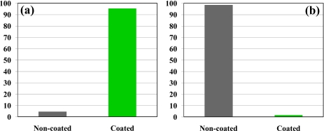
The throughput of the demonstrated charge-based particle separation through DEP in the spiral microchannel was 150–200 beads∕min as estimated from the video. It can be greatly enhanced if a higher particle concentration and a deeper channel are used because the demonstrated DEP does not depend on the channel depth.62 We also tested the efficiency of this separation by counting the number of dark noncoated and bright coated beads in the three outlet reservoirs. Figure 4 shows the percentages of these two types of beads in outlet reservoirs 1 and 2, respectively, where a total of over 800 beads were counted. No beads were noticed in outlet reservoir 3. It was found that over 95% of the beads collected in outlet reservoir 1 are coated beads while over 98% of the beads in outlet reservoir 2 are noncoated beads.
Figure 4.
Percentages of the coated and noncoated 10 μm beads in outlet reservoir 1 (a) and outlet reservoir 2 (b) of the spiral microchannel after the charge-based separation using curvature-induced DEP.
Effect of the voltage at the inlet reservoir
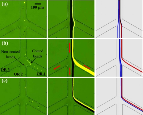
We also studied experimentally and numerically how the voltage at the inlet reservoir affects the dielectrophoretic separation of noncoated (dark) and carboxyl-coated (bright) 10 μm beads in the spiral microchannel. Figure 5 (left for snapshot images, middle for superimposed images, and right for numerical predictions) shows the particle behaviors in the trifurcation region under the inlet voltages of 200 V (a), 400 V (b), and 600 V (c), respectively. The three outlet reservoirs were grounded in all cases. The 400 V case has been explained above, where the electric field in the first spiral is sufficient to focus both types of beads into a single stream near the outer channel wall for subsequent complete separation in the second spiral; see Fig. 5b. If, however, the inlet voltage is decreased to 200 V, the resulting 80 V∕cm electric field in the first spiral is barely enough to deflect even the coated beads (with a larger mobility ratio μDEP∕μEK) to the outer channel wall. As shown in Fig. 5a the coated and noncoated beads both moved into reservoir 2 without a separation. When the inlet voltage was increased from 400 V to 600 V, both types of beads were over-focused in the first spiral. As such, the lateral displacement between the two particle sub-streams in the second spiral was small so that all particles were collected in outlet reservoir 1 without a separation, which is illustrated in Fig. 5c. One can see that the numerically predicted particle trajectories agree reasonably with the experimental results in all three cases.
Figure 5.
Effects of the dc voltage at the inlet reservoir on the binary separation of plain noncoated (dark) and fluorescent carboxyl-coated (bright) 10 μm polystyrene beads in the spiral microchannel: (a) 200 V, (b) 400 V, and (c) 600 V. The three outlet reservoirs, labeled as OR 1–3 in (b), were grounded in all cases. The three columns from left to right show the snapshot image, superimposed image, and numerical prediction in the trifurcation region of the channel, respectively. The block arrows indicate the flow directions in all three cases.
Effect of the voltages at the outlet reservoirs
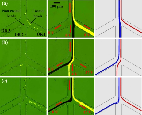
Further, we studied experimentally and numerically how the dc voltages at the outlet reservoirs may affect the binary separation of noncoated (dark) and carboxyl-coated (bright) 10 μm beads in the spiral microchannel. This is presented in Fig. 6, where the three columns from left to right display the snapshot images, superimposed images, and numerical predictions. The inlet voltage was fixed at 400 V. Figure 6a shows the exact case that we have explained in Fig. 3 and revisited in Fig. 5b, where the three outlets were all grounded so that the coated and noncoated beads were sorted into outlet reservoirs 1 and 2, respectively. However, when the voltages at these two reservoirs were tuned to 37 and 4 V, we observed that the coated and non-coated beads were sorted into reservoirs 2 and 3, respectively, as demonstrated in Fig. 6b. This is because the new voltages at the outlet reservoirs changed the flow splitting at the trifurcation and redirected the majority of the flow toward outlet reservoirs 2 and 3. We also implemented the separation of coated and noncoated beads into outlet reservoirs 1 and 3, respectively, as seen in Fig. 6c. For this to happen, we floated outlet reservoir 2 and applied a 12 V to outlet reservoir 1 while still maintaining outlet reservoir 3 grounded. As such, there was actually no flow into reservoir 2 during the particle separation. These observed particle separation behaviors are all reasonably predicted by the numerical model as demonstrated in Fig. 6 (right column).
Figure 6.
Effects of the DC voltages at the outlet reservoirs, labeled as OR 1–3 in (a), on the binary separation of plain noncoated (dark) and fluorescent carboxyl-coated (bright) 10 μm polystyrene beads in the spiral microchannel. The outlet voltages for each case are marked on the images in the middle column. The inlet voltage was fixed at 400 V in all three cases. The three columns from left to right show the snapshot image, superimposed image, and numerical prediction in the trifurcation region of the channel, respectively. The block arrows indicating flow directions during the separation.
Ternary separation of particles by change and size
To test the versatility of dielectrophoretic separation in spiral microchannels, we conducted another experiment to attempt a ternary separation of particles by charge and size simultaneously. For this purpose, we fabricated a new spiral microchannel that is similar to the one in Fig. 1 but with a doubled width everywhere. The gap distances between neighboring loops were also adjusted accordingly, yielding a total channel length of 46 mm. Plain noncoated 5 μm beads were added into the above-used binary particle mixture, which was then resuspended in 0.1 mM phosphate buffer (electric conductivity measured 26 μS∕cm) for an improved separation. Using the method described earlier, we obtained the electrokinetic mobility, μEK=4.3×10⁻⁸, 4.5×10⁻⁸, and 2.2×10⁻⁸ m2∕V s for the noncoated 5 μm, noncoated 10 μm, and coated 10 μm beads, respectively. As the dielectrophoretic mobility, μDEP, is proportional to particle diameter squared [see Eq. 2], it is expected that the mobility ratio, μDEP∕μEK, of 5 μm beads is about one-quarter of that of the noncoated 10 μm beads. The mobility ratio of the coated 10 μm beads is the largest among the three due to their smallest electrokinetic mobility.
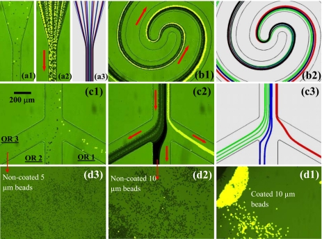
Figure 7 shows the experimental observation and numerical prediction of the ternary separation of particles by charge and size. The dc voltage at the inlet reservoir is 1000 V, and those at the outlet reservoirs 1–3 are 33, 20, and 0 V, respectively. The computed electric field in the first spiral is about 330 V∕cm on average, which as explained earlier, served to deflect and focus with DEP all three types of beads [see Fig. 7(a1)] (enhanced) to a single stream near the outer wall of the first spiral. Subsequently the discrepancy in the particle mobility ratio led to differential lateral displacements of the focused bead streams in the second spiral [see Fig. 7(b1)] (enhanced). As such, the coated 10 μm beads, noncoated 10 μm beads, and noncoated 5 μm beads were sorted into outlet reservoirs 1–3, respectively, as demonstrated in Figs. 7(c1) (snapshot image, enhanced) and 7(c2) (superimposed image). This whole process is once again reasonably predicted by the numerical model as demonstrated in Fig. 7 (see a2, b2, c3), where the red, blue, and green lines represent the trajectories of coated 10 μm beads, noncoated 10 μm beads, and noncoated 5 μm beads, respectively. The correction factor for dielectrophoretic velocity, c, was set to 0.4 and 0.6 for the 10 and 5 μm beads, respectively, both of which are consistent with previous studies.49, 54, 62, 64, 75
Figure 7.
Continuous ternary separation of plain noncoated 5 μm (gray), plain noncoated 10 μm (dark), and fluorescent carboxyl-coated 10 μm (bright) polystyrene beads in a spiral microchannel using curvature-induced DEP: snapshot image (a1) (enhanced), superimposed image (a2) and numerical prediction (a3) in the inlet region; superimposed image (b1) (enhanced) and numerical prediction (b2) in the center region; snapshot image (c1) (enhanced), superimposed image (c1) and numerical prediction (c3) in the trifurcation region; top-view images (d1, d2 and d3) of the particles sorted into the three outlet reservoirs, labeled as OR 1–3 in (a1). The block arrows indicate the flow directions (enhanced online). [URL: http//dx.doi.org/10.1063/1.3599883.1] [URL: http//dx.doi.org/10.1063/1.3599883.1] [URL: http//dx.doi.org/10.1063/1.3599883.1]
The particle throughput of this demonstrated ternary separation is estimated to be at least 1000 beads∕min from the video, which can be further improved by increasing the channel depth or the particle concentration. We ran this ternary separation experiment for over 10 min without interruption and adjustment. After that we took an image (top view) of each of the three outlet reservoirs, which, as seen in Fig. 7 (d1, d2 and d3 for outlet reservoirs 1, 2 and 3, respectively), indicates a high separation efficiency of the three types of beads by charge and size simultaneously.
CONCLUSIONS
We have demonstrated a continuous binary separation of particles by surface charge in a double-spiral microchannel using curvature-induced DEP. The effects of the dc voltages applied to the inlet and outlet reservoirs on the particle separation have been examined systematically. As compared to the traditional elution-based capillary electrophoresis1, 6 and field flow fractionation7 for charge-based separation, this demonstrated DEP technique has the advantage of continuous-flow process and is thus more suitable for integration with pre- and∕or postseparation parts into lab-on-a-chip devices. We have also implemented a continuous ternary separation of particles by charge and size in a similar spiral microchannel. Moreover, the observed particle separation processes in different situations are all reasonably predicted by a numerical model. These experiments demonstrate that the developed curvature-induced DEP technique may be used with potential to separate multiple particle targets by their intrinsic properties (e.g., particle size, charge, and conductivity).
ACKNOWLEDGMENTS
This work was supported by NSF under Grant No. CBET-0853873 and by Clemson University through a start-up package.
References
- Rodriguez M. A. and Armstrong D. W., J. Chromatogr. B Analyt. Technol. Biomed. Life Sci. 800, 7 (2004). 10.1016/j.jchromb.2003.09.060 [DOI] [PubMed] [Google Scholar]
- Pamme N., Lab Chip 7, 1644 (2007). 10.1039/b712784g [DOI] [PubMed] [Google Scholar]
- Kersaudy-Kerhoas M., Dhariwal R., and Desmulliez M. P., IET Nanobiotechnol. 2, 1 (2008). 10.1049/iet-nbt:20070025 [DOI] [PubMed] [Google Scholar]
- Sethu P., Sin A., and Toner M., Lab Chip 6, 83 (2006). 10.1039/b512049g [DOI] [PubMed] [Google Scholar]
- Dainiak M. B., Plieva F. M., Galaev I. Y., Hatti-Kaul R., and Mattiasson B., Biotechnol. Prog. 21, 644 (2005). 10.1021/bp049615g [DOI] [PubMed] [Google Scholar]
- Kremser L., Blaas D., and Kenndler E., Electrophoresis 25, 2282 (2004). 10.1002/elps.200305868 [DOI] [PubMed] [Google Scholar]
- Giddings J. C., Science 260, 1456 (1993). 10.1126/science.8502990 [DOI] [PubMed] [Google Scholar]
- Tsutsui H. and Ho C. M., Mech. Res. Commun. 36, 92 (2009). 10.1016/j.mechrescom.2008.08.006 [DOI] [PMC free article] [PubMed] [Google Scholar]
- Lenshof A. and Laurell T., Chem. Soc. Rev. 39, 1203 (2010). 10.1039/b915999c [DOI] [PubMed] [Google Scholar]
- Gossett D. R., Weaver W. M., Mach A. J., Hur S. C., Tse H. T. K., Lee W., Amini H., and Di Carlo D., Anal. Bioanal. Chem. 397, 3249 (2010). 10.1007/s00216-010-3721-9 [DOI] [PMC free article] [PubMed] [Google Scholar]
- Huh D., Bahng J. W., Ling Y., Wei H., Kripfgans O. D., Fowlkes J. B., Grotberg J. B., and Takayama S., Anal. Chem. 79, 1369 (2007). 10.1021/ac061542n [DOI] [PMC free article] [PubMed] [Google Scholar]
- Zhang C. X. and Manz A., Anal. Chem. 75, 5759 (2003). 10.1021/ac0345190 [DOI] [PubMed] [Google Scholar]
- Kim S. B., Yoon S. Y., Sung H. J., and Kim S. S., Anal. Chem. 80, 2628 (2008). 10.1021/ac8000918 [DOI] [PubMed] [Google Scholar]
- Pamme N., Lab Chip 6, 24 (2006). 10.1039/b513005k [DOI] [PubMed] [Google Scholar]
- Shi J. J. Huang H., Stratton Z., Huang Y. P., and Huang T. J., Lab Chip 9, 3354 (2009). 10.1039/b915113c [DOI] [PubMed] [Google Scholar]
- Takagi J., Yamada M., Yasuda M., and Seki M., Lab Chip 5, 778 (2005). 10.1039/b501885d [DOI] [PubMed] [Google Scholar]
- Davis J. A., Inglis D. W., Morton K. J., Lawrence D. A., Huang L. R., Chou S. Y., Sturm J. C., and Austin R. H., Proc. Natl. Acad. Sci. U.S.A. 103, 14779 (2006). 10.1073/pnas.0605967103 [DOI] [PMC free article] [PubMed] [Google Scholar]
- Yamada M. and Seki M., Lab Chip 5, 1233 (2005). 10.1039/b509386d [DOI] [PubMed] [Google Scholar]
- Choi S. Y. and Park J. K., Lab Chip 9, 1962 (2009). 10.1039/b820364d [DOI] [PubMed] [Google Scholar]
- Wu Z. G., Willing B., Bjerketorp J., Jansson J. K., and Hjort K., Lab Chip 9, 1193 (2009). 10.1039/b817611f [DOI] [PubMed] [Google Scholar]
- Kuntaegowdanahalli S. S., Bhagat A. A. S., Kumar G., and Papautsky I., Lab Chip 9, 2973 (2009). 10.1039/b908271a [DOI] [PubMed] [Google Scholar]
- Di Carlo D., Lab Chip 9, 3038 (2009). 10.1039/b912547g [DOI] [PubMed] [Google Scholar]
- Pohl H. A., Dielectrophoresis: The Behavior of Neutral Matter in Non-Uniform Electric Fields (Cambridge University Press, Cambridge, 1978). [Google Scholar]
- Velev O. D. and Bhatt K. H., Soft Matter 2, 738 (2006). 10.1039/b605052b [DOI] [PubMed] [Google Scholar]
- Lapizco-Encinas B. H. and Rito-Palmomares M., Electrophoresis 28, 4521 (2007). 10.1002/elps.200700303 [DOI] [PubMed] [Google Scholar]
- Hawkins B. G., Gleghorn J. P., and Kirby B. J., in Methods in Bioengineering: Biomicrofabrication and Biomicrofluidics, edited by Zahn J. D. (Artech House, Inc., 2009), pp. 133–181. [Google Scholar]
- Pethig R., Biomicrofluidics 4, 022811 (2010). 10.1063/1.3456626 [DOI] [PMC free article] [PubMed] [Google Scholar]
- Gascoyne P. R. C. and Vykoukal J., Electrophoresis 23, 1973 (2002). [DOI] [PMC free article] [PubMed] [Google Scholar]
- Hughes M. P., Electrophoresis 23, 2569 (2002). [DOI] [PubMed] [Google Scholar]
- Chou C. -F. and Zenhausern F., IEEE Eng. Med. Biol. Mag. 22, 62 (2003). 10.1109/MEMB.2003.1266048 [DOI] [PubMed] [Google Scholar]
- Cummings E. B., IEEE Eng. Med. Biol. Mag. 22, 75 (2003). 10.1109/MEMB.2003.1266050 [DOI] [PubMed] [Google Scholar]
- Srivastava S. K., Gencoglu A., and Minerick A. R., Anal. Bioanal. Chem. 399, 301 (2011). 10.1007/s00216-010-4222-6 [DOI] [PubMed] [Google Scholar]
- Choi S. and Park J. K., Lab Chip 5, 1161 (2005). 10.1039/b505088j [DOI] [PubMed] [Google Scholar]
- Kralj J. G., Lis M. T. W., Schmidt M. A., and Jensen K. F., Anal. Chem. 78, 5019 (2006). 10.1021/ac0601314 [DOI] [PubMed] [Google Scholar]
- Cheng I. F., Chang H. C., Hou D., and Chang H. C., Biomicrofluidics 1, 021503 (2007). 10.1063/1.2723669 [DOI] [Google Scholar]
- Demierre N. Braschler T. Linderholm P., Seger U., van Lintel H., and Renaud P., Lab Chip 7, 355 (2007). 10.1039/b612866a [DOI] [PubMed] [Google Scholar]
- Vahey M. D. and Voldman J., Anal. Chem. 80, 3135 (2008). 10.1021/ac7020568 [DOI] [PubMed] [Google Scholar]
- Wang L., Lu J., Marchenko S. A., Monuki E. S., Flanagan L. A., and Lee A. P., Electrophoresis 30, 782 (2009). 10.1002/elps.200800637 [DOI] [PubMed] [Google Scholar]
- Khoshmanesh K., Zhang C., Tovar-Lopez F. J., Nahavandi S., Baratchi S., Kalantar-zadeh K., and Mitchell A., Electrophoresis 30, 3707 (2009). 10.1002/elps.200900079 [DOI] [PubMed] [Google Scholar]
- Ou J., Carpenter S. J., and Dorfman K. D., Biomicrofluidics 4, 013203 (2010). 10.1063/1.3283903 [DOI] [PMC free article] [PubMed] [Google Scholar]
- Lewpiriyawong N., Yang C., and Lam Y. C., Electrophoresis 31, 2622 (2010). 10.1002/elps.201000087 [DOI] [PubMed] [Google Scholar]
- Thomas R. S. W., Mitchell P. D., Oreffo R. O. C., and Morgan H., Biomicrofluidics 4, 022806 (2010). 10.1063/1.3406951 [DOI] [PMC free article] [PubMed] [Google Scholar]
- Valero A., Braschler T., Demierre N., and Renaud P., Biomicrofluidics 4, 022807 (2010). 10.1063/1.3430542 [DOI] [PMC free article] [PubMed] [Google Scholar]
- Zhu K., Kaprelyants A. S., Salina E. G., and Markx G. H., Biomicrofluidics 4, 022809 (2010). 10.1063/1.3435335 [DOI] [PMC free article] [PubMed] [Google Scholar]
- Shafiee H., Caldwell J. L., Sano M. B., and Davalos R. D., Biomed. Microdevices 11, 997 (2009). 10.1007/s10544-009-9317-5 [DOI] [PubMed] [Google Scholar]
- Shafiee H., Sano M. B., Henslee E. A., Caldwell J. L., and Davalos R. D., Lab Chip 10, 438 (2010). 10.1039/b920590j [DOI] [PubMed] [Google Scholar]
- Lapizco-Encinas B. H., Simmons B. A., Cummings E. B., and Fintschenko Y., Electrophoresis 25, 1695 (2004). 10.1002/elps.200405899 [DOI] [PubMed] [Google Scholar]
- Barrett L. M., Skulan A. J., Singh A. K., Cummings E. B., and Fiechtner G. J., Anal. Chem. 77, 6798 (2005). 10.1021/ac0507791 [DOI] [PubMed] [Google Scholar]
- Kang K., Kang Y., Xuan X., and Li D., Electrophoresis 27, 694 (2006). 10.1002/elps.200500558 [DOI] [PubMed] [Google Scholar]
- Pysher M. D. and Hayes M. A., Anal. Chem. 79, 4552 (2007). 10.1021/ac070534j [DOI] [PubMed] [Google Scholar]
- Hawkins B. G., Smith A. E., Syed Y. A., and Kirby B. J., Anal. Chem. 79, 7291 (2007). 10.1021/ac0707277 [DOI] [PubMed] [Google Scholar]
- Lewpiriyawong N., Yang C., and Lam Y. C., Biomicrofluidics 2, 034105 (2008). 10.1063/1.2973661 [DOI] [PMC free article] [PubMed] [Google Scholar]
- Kang Y., Li D., Kalams S. A., and Eid J. E., Biomed. Microdevices 10, 243 (2008). 10.1007/s10544-007-9130-y [DOI] [PubMed] [Google Scholar]
- Zhu J. and Xuan X., Electrophoresis 30, 2668 (2009). 10.1002/elps.200900017 [DOI] [PubMed] [Google Scholar]
- Chen D. F. and Du H. J., Microfluid. Nanofluid. 9, 281 (2010). 10.1007/s10404-009-0545-z [DOI] [Google Scholar]
- Baylon-Cardiel J. L., Jesus-Perez N. M., Chavez-Santoscoy A. V., and Lapizco-Encinas B. H., Lab Chip 10, 3235 (2010). 10.1039/c0lc00097c [DOI] [PubMed] [Google Scholar]
- Srivastava S. K., Baylon-Cardiel J. L., Lapizco-Encinas B. H., and Minerick A. R., J Chromatogr. A 1218, 1780 (2011). 10.1016/j.chroma.2011.01.082 [DOI] [PubMed] [Google Scholar]
- Hawkins B. G. and Kirby B. J., Electrophoresis 31, 3622 (2010). 10.1002/elps.201000429 [DOI] [PubMed] [Google Scholar]
- Sridharan S., Zhu J., Hu G., and Xuan X., Electrophoresis 32 (2011). 10.1002/elps.201100011 [DOI] [PubMed] [Google Scholar]
- Voldman J., Annu. Rev. Biomed. Eng. 8, 425 (2006). 10.1146/annurev.bioeng.8.061505.095739 [DOI] [PubMed] [Google Scholar]
- Goet G., Baier T., and Hardt S., Biomicrofluidics 5, 014109 (2011). 10.1063/1.3555194 [DOI] [PMC free article] [PubMed] [Google Scholar]
- Zhu J., Tzeng T. J., Hu G., and Xuan X., Microfluid. Nanofluid. 7, 751 (2009). 10.1007/s10404-009-0432-7 [DOI] [Google Scholar]
- Church C., Zhu J., Wang G., Tzeng T. J., and Xuan X., Biomicrofluidics 3, 044109 (2009). 10.1063/1.3267098 [DOI] [PMC free article] [PubMed] [Google Scholar]
- Zhu J. and Xuan X., J. Colloid Interface Sci. 340, 285 (2009). 10.1016/j.jcis.2009.08.031 [DOI] [PubMed] [Google Scholar]
- Ai Y., Park S., Zhu J., Xuan X., Beskok A., and Qian S., Langmuir 26, 2937 (2010). 10.1021/la902711x [DOI] [PubMed] [Google Scholar]
- Church C., Zhu J., Nieto J., Keten G., Ibarra E., and Xuan X., J. Micromech. Microeng. 20, 065011 (2010). 10.1088/0960-1317/20/6/065011 [DOI] [Google Scholar]
- Church C., Zhu J., and Xuan X., Electrophoresis 32, 527 (2011). 10.1002/elps.201000396 [DOI] [PubMed] [Google Scholar]
- Zhu J., Tzeng T. J., and Xuan X., Electrophoresis 31, 1382 (2010). 10.1002/elps.200900736 [DOI] [PubMed] [Google Scholar]
- Sun J., Vajandar S. K., Xu D., Kang Y., Hu G., Li D., and Li D., Microfluid. Nanofluid. 6, 589 (2009). 10.1007/s10404-008-0331-3 [DOI] [Google Scholar]
- Morgan H. and Green N. G., Electrokinetic: Colloids and Nanoparticles (Research Studies Press, Hertfordshire, UK, 2002). [Google Scholar]
- Cummings E. B., Griffiths S. K., Nilson R. H., and Paul P. H., Anal. Chem. 72, 2526 (2000). 10.1021/ac991165x [DOI] [PubMed] [Google Scholar]
- Kirby B. J., Micro- and Nanoscale Fluid Mechanics: Transport in Microfluidic Devices (Cambridge University Press, Cambridge, 2010), pp. 467–481. [Google Scholar]
- Ermolina I. and Morgan H., J. Colloid Interface Sci. 285, 419 (2005). 10.1016/j.jcis.2004.11.003 [DOI] [PubMed] [Google Scholar]
- Pethig R. and Markx G. H., Trends Biotechnol. 15, 426 (1997). 10.1016/S0167-7799(97)01096-2 [DOI] [PubMed] [Google Scholar]
- Hyoung Kang K., Xuan X., Kang Y., and Li D., J. Appl. Phys. 99, 064702 (2006). 10.1063/1.2180430 [DOI] [Google Scholar]
- Church C., Zhu J., Huang G., Tzeng T. J., and Xuan X., Biomicrofluidics 4, 044101 (2010). 10.1063/1.3496358 [DOI] [PMC free article] [PubMed] [Google Scholar]
- Liang L., Ai Y., Zhu J., Qian S., and Xuan X., J. Colloid Interface Sci. 347, 142 (2010). 10.1016/j.jcis.2010.03.039 [DOI] [PubMed] [Google Scholar]
- Liang Li., Qian S., and Xuan X., J. Colloid Interface Sci. 350, 377 (2010). 10.1016/j.jcis.2010.06.067 [DOI] [PubMed] [Google Scholar]


