

Abstract
F1-ATPase is a water-soluble portion of FoF1-ATP synthase and rotary molecular motor that exhibits reversibility in chemical reactions. The rotational motion of the shaft subunit γ has been carefully scrutinized in previous studies, but a tilting motion of the shaft has never been explicitly postulated. Here we found a change in the radius of rotation of the probe attached to the shaft subunit γ between two different intermediate states in ATP hydrolysis: one waiting for ATP binding, and the other waiting for ATP hydrolysis and/or subsequent product release. Analysis of this radial difference indicates a ∼4° outward tilting of the γ-subunit induced by ATP binding. The tilt angle is a new parameter, to our knowledge, representing the motion of the γ-subunit and provides a new constraint condition of the ATP-waiting conformation of F1-ATPase, which has not been determined as an atomic structure from x-ray crystallography.
Introduction
FoF1-ATP synthase is a molecular motor exhibiting reversibility of ATP hydrolysis and synthesis (1–3). The F1 sector containing α3β3γδε subunits, called F1-ATPase, solely hydrolyzes ATP when isolated and the hydrolysis accompanies counterclockwise rotation of the γ-subunit when viewed from the protruded side (4,5). Inversely, when the common shaft is forced to rotate in a clockwise manner by the Fo portion using the proton-motive force across a membrane, ATP is synthesized from ADP and inorganic phosphate in three catalytic sites located at the interface between the noncatalytic α-subunit and the catalytic β-subunit (6). The crystal structure of F1-ATPase revealed that three noncatalytic α-subunits and three catalytic β-subunits are alternately arranged around the central shaft γ-subunit and three catalytic sites are in different chemical states (7,8).
The coiled-coil domain of the γ-subunit is not essential for the rotational movement, but the rotation rate is greatly reduced by truncation of the coiled-coil domain (9). This study indicates that the γ-subunit essentially mediates the cooperative reactions in the three catalytic sites, and thus F1-ATPase achieves a high efficiency of chemical reaction. Therefore, how the γ-subunit interacts with the other subunits is critical for understanding the rotation mechanism of F1-ATPase. However, following the demonstration of rotation of the γ-subunit and measurement of its rotation angle by single-molecule measurement, other motions were not as widely investigated. We hypothesized that a tilting motion of the γ-subunit should occur in addition to its horizontal rotation: the x-ray crystal structure clearly indicates that the C-terminal domain in the β-subunit accompanies the bending motion in the vertical direction from the open form (βE) to the closed form (βTP); the short helix of the γ-subunit (residues 80–96 in F1-ATPase from bovine mitochondria) directly interacts with the C-terminal domain in the βTP subunit (7,10). Here, we scrutinize the radius of rotation in an isolated α3β3γ subcomplex (hereafter referred to as F1) under an optical microscope and report a change in the radius of rotation, which notably indicates a tilting motion of the γ-subunit between two chemical states.
Materials and Methods
Preparation of F1
The α3β3γ subcomplex of F1-ATPase was derived from thermophilic Bacillus PS3. For the rotation assay, we used the α3 β(His-10 at N-terminus)3 γ(S109C/I212C), which is referred to as the wild-type (WT) F1 in main text, and the α3 β(His-10 at N-terminus/E190D)3 γ(S109C/I212C), which is referred to as F1(βE190D). These subcomplexes were expressed in Escherichia coli, purified, and biotinylated as reported elsewhere (11).
Microscopy
The rotation of a polystyrene bead on the γ-subunit was visualized by center-stop darkfield microscopy (11) using an inverted microscope (IX71; Olympus, Tokyo, Japan) with an objective lens (Plan Apo 100× or 60×, NA 1.45; Olympus), a center stop (circular reticle with ϕ = 500 μm; Qioptiq Photonics GmbH & Co KG, Göttingen, Germany), a halogen lamp and a charge-coupled device (CCD) camera (Luca; Andor Technologies, Belfast, Ireland /CCD-300-RCX; Dage-MTI, Michigan City, IN). The rotation of a gold nanoparticle was visualized by objective-type total internal reflection darkfield microscopy (12) using an inverted microscopy (IX71; Olympus) with an objective lens (Plan Apo 60×, NA 1.45; Nikon, Tokyo, Japan), a laboratory-made perforated mirror (ϕ = 6 mm), a 532-nm laser (Compass 215M-50; Coherent, Santa Clara, CA), and a CCD camera (Luca; Andor Technologies).
Rotation assay
The methods for rotation assay were described previously (11,12), except that the present assay mixture contained 10 mM HEPES-KOH, pH 8.0, 1 mM MgCl2, and ATP, along with an ATP-regenerating system (0.020 mg/ml creatine kinase and 0.082 mg/ml creatine phosphate). Observations were made at 24 ± 2°C.
Results
Change in radius of rotation of the mutant F1
In the rotation assay, we used a single polystyrene bead or a spherical nanoparticle as a probe. Unlike an actin filament or duplex bead, these probes are symmetrical about all (x, y, and z) axes and therefore their projected shapes onto the x-y plane are not changed when the γ-subunit is tilted, which enables us to measure the radius of rotation quantitatively. F1 from thermophilic Bacillus PS3 (TF1) was used. The γ-subunit was biotinylated to attach a streptavidin-coated probe specifically. The resulting F1-probe conjugates were immobilized on a glass and imaged using darkfield microscopy (11,12).
In ATP hydrolysis, the unitary step of 120° consists of an 80° substep triggered by ATP binding and a 40° substep after the catalytic events (chemical cleavage of ATP and release of the product Pi) (13–16). The dwells before the 80° substeps were hence named ATP-waiting dwells, and those before the 40° substeps, catalytic dwells. To distinguish between these dwells, we used the mutant F1(βE190D), which cleaves ATP 100-fold more slowly (its reported ATP cleavage rate is ∼3 s−1 (16)), so that the 80° and 40° substep can be observed at the video rate. As with the rotation assay of F1(βE190D) previously reported (16), the alternating steps of ∼80° and ∼40° were observed (Fig. 1 A inset). The plots of the position of the 220-nm polystyrene bead clearly showed six dwelling points, identifying three ATP-waiting dwells and three catalytic dwells (Fig. 1 B). We found that a circle circumscribing the triangle formed by the three catalytic dwells was clearly outside the circle circumscribing the three ATP-waiting dwells (Fig. 1 B). We also confirmed this finding by calculating the distances between the dwelling point in each dwell and the circumcenter of ATP-waiting dwells. The mean distance of the catalytic dwells (at 80°, 200°, 320°) tended to be larger than that of the ATP-waiting dwells (at 0°, 120°, 240°) (Fig. 1 C).
Figure 1.

Observation of rotation of the F1(βE190D) with a single 220-nm polystyrene bead at 2 μM ATP at 30 frames per second. (A) Time course of rotation. Inset, magnified trajectory from the area indicated by brown lines. The horizontal gray lines are 80° and 40° apart. (B) Trace of a single bead rotation (purple solid circle) in ∼1800 consecutive frames. Blue and red dotted lines represent the circumscribed circles of the three ATP-waiting dwells and the three catalytic dwells, respectively. (C) Mean distances in each dwell from the circumcenter of the ATP-waiting dwells. The ATP-waiting dwells and the catalytic dwells are indicated by blue and red solid circles, respectively. (D) Histogram of the difference between circumradii of the ATP-waiting dwells and the catalytic dwells.
We observed the rotations of 93 molecules and measured, in each molecule, these two circumradii, each of which included three averaged points of dwells that were ∼120° apart. The radius of rotation of catalytic dwells was always larger than that of ATP-waiting dwells, and the difference was estimated to be 2.6 ± 1.0 nm (mean ± SD, Fig. 1 D). Possible explanations for this 2.6-nm displacement include translation, or, alternatively, tilting of the γ-subunit at the transition from the ATP-waiting dwell to the catalytic dwell. We considered this point from known atomic structures of the α3β3γ complex. Because an atomic structure of TF1 has not been reported, the crystal structures of bovine mitochondrial F1-ATPase were used to measure the cavity size of the α3β3 cylinder (7,10). The distance between Cα of E292 of the α-subunit and Cα of A278 of the β-subunit at the opposite side was typically only 1.7 nm (Fig. S1 and Fig. S2 in the Supporting Material). Considering this cavity size of the α3β3 cylinder and the diameter of the γ-subunit itself, we surmise that the radial displacement of 2.6 nm is not attributable to a translation of the coiled-coil domain of the γ-subunit. Furthermore, because the domain of the γ-subunit that protrudes from the α3β3 cylinder has been suggested to be relatively rigid or stably folded (17), this part of the γ-subunit is unlikely to undergo such a large conformational change that can result in the ∼3-nm extension that is necessary to result in the observed change of rotation radius (Fig. S2). Therefore, the tilting motion of the γ-subunit is the most probable cause for the change in the radius of rotation between the two different chemical states (Fig. S2).
Change in radius of rotation of the WT F1
Next, we performed an experiment using the WT F1. In the WT F1, the catalytic dwelling points cannot be observed at the video rate because the time constant of the catalytic dwell is only a few milliseconds (15). Instead, we analyzed the position of long pauses (the time constant of 30∼100 s) caused by ADP inhibition, which occasionally occurs at the same angle as the catalytic dwells (18). The probe position in the ADP inhibited state was obviously outside the circumscribed circle of the ATP-waiting dwells (Fig. 2 A). The radial displacement of the ADP inhibited state was 2.3 ± 3.7 nm (mean ± SD; n = 18 in 16 molecules, paired t-test p < 0.02) (Fig. 2 B), comparable to the results for F1(βE190D). Furthermore, we also performed the experiment using ATPγS, in which the catalytic dwell was extended to ∼70 ms (16), instead of ATP. The rotation trajectory in the presence of ATPγS was similar to that of F1(βE190D) (Fig. 2 C, see also Fig. 1 B). The difference in the radius of rotation between the ATP-waiting dwells and catalytic dwells was 2.5 ± 1.7 nm (mean ± SD; n = 32 molecules, Fig. 2 D). Therefore, the radial displacement in rotation is a general feature of F1. Furthermore, we note that in this particular case (Fig. 2 C) the two circles were not concentric, but whether or not the circles are concentric does not affect the result that the circumradius of the catalytic dwells is larger than that of the ATP-waiting dwells (see also Fig. S3).
Figure 2.
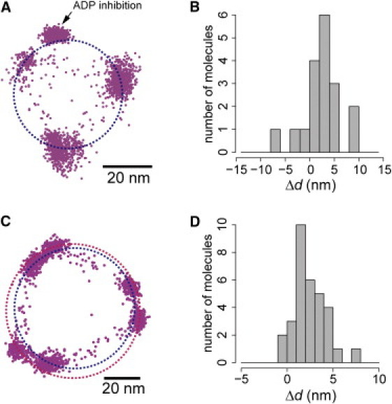
Observation of rotation of the WT F1. (A) Trace of consecutive rotation, and the pause due to ADP-inhibition (arrow), observed with a single 220-nm polystyrene bead at 0.2 μM ATP at 30 frames per second. (B) Histogram of the displacement of the pause of ADP inhibition from the circumradius of the ATP-waiting dwells. (C) Trace of rotation of the WT observed with a single 108-nm polystyrene bead at 1 μM ATPγS at 200 frames per second. (D) Histogram of difference between circumradii of the ATP-waiting dwells and the catalytic dwells in the presence of ATPγS.
Evaluation of the tilt angle of the γ-subunit
We assume hereafter that the main cause of the change in radius of rotation is the tilting of the shaft, and quantitatively evaluate the angle of the tilting. To do this, markers with different diameters were employed in addition to the 220-nm polystyrene bead: a 108-nm single polystyrene bead, 489-nm single polystyrene bead, and 40-nm Au nanoparticle. Fig. 3 summarizes the relationship between the circumradius of the ATP-waiting dwells and that of the catalytic dwells in all experiments using F1(βE190D). We evaluated the tilt angle of the γ-subunit by trigonometry (Fig. 3 A), and estimated the angles as 0.8°, 1.3°, 2.6°, and 3.7° with 489-nm, 220-nm, 108-nm, and 40-nm markers, respectively (Fig. 3, B–E). The results showed that the γ-subunit tilted up to ∼4° at the transition from the ATP-waiting dwell to the catalytic dwell, and notably, the rotation of the shaft itself was not disturbed even when the angle was reduced to ∼1°, which was likely due to hindrance of the large markers. In the case of the WT F1 in the presence of ATPγS with a single 108-nm polystyrene bead, the tilt angle of the γ-subunit was 2.8°, which is consistent with that of F1(βE190D) with a single 108-nm bead (Fig. S4). Note that in all observed molecules, the triangles of the ATP-waiting dwells or the catalytic dwells were acute triangles, meaning all circumcenters of the ATP-waiting dwells or the catalytic dwells were inside the triangles.
Figure 3.
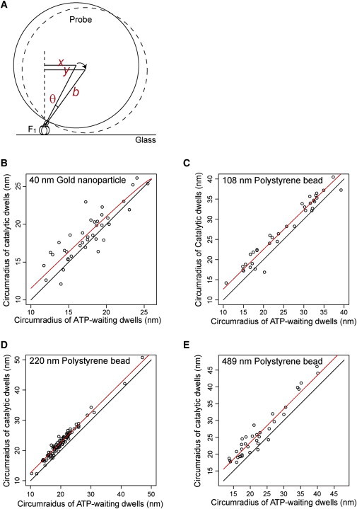
Evaluation of the tilt angle of the γ-subunit. (A) Schematic diagrams of the geometry of the rotation assay. The relationship of the circumradius of the ATP-waiting dwells (x nm) and that of catalytic dwells (y nm) was expressed by the formula , where θ is the tilt angle from the ATP-waiting dwell to the catalytic dwell, and b is the radius of the probe including the size of streptavidin (5 nm) and the linker length of biotinylation (1 nm). (B–E) Relationship between the circumradius of the ATP-waiting dwells and that of the catalytic dwells. Each point represents one molecule. The red line represents the fitting line by the formula. The black line represents the line y = x, meaning that the circumradius of the catalytic dwells is equal to that of the ATP-waiting dwells.
Discussion
This study shows that the radius of rotation of the γ-subunit is different between the ATP-waiting dwells and the catalytic dwells. This finding was confirmed not only by analysis of the ATP-driven rotation of the F1(βE190D) mutant, which cleaved ATP 100-fold more slowly, but also by examination of the ATPγS-driven rotation of the WT F1. The circumradius of the three dwelling points of the probe at the catalytic dwell was larger than that at the ATP-waiting dwell (Figs. 1 and 2), and this tendency was quantitatively confirmed by four markers with different diameters (Fig. 3). We conclude that our observation was most likely attributable to the tilting of the shaft, because 1), the radius change was dependent on the size of the marker; and 2), other factors, such as a shift or an elongation of the subunit parallel to the surface, were improbable when we take the protein size and structure into account. We also found that dwelling points at the ADP-inhibition state were located outside the circumradius of the three ATP-waiting dwells (Fig. 2, A and B). It has been reported that rotation angles are similar at the states between ADP inhibition and catalytic dwell (16,18). Here, our results indicate that the tilting direction is also the same between these two different chemical states. This similarity would be important when atomic structures of F1-ATPase revealed by crystallography are compared and assessed in terms of their chemical states.
The crucial characteristic of radius change revealed herein has presumably been overlooked in previous contributions, although it can be observed in rotation traces. Many of the researchers in this field prefer to use asymmetric probes, such as an actin filament of micrometer size (4,5), a bead duplex (11,14,15,18), or magnetic beads (13), to increase the resolution in the rotational direction of the shaft. These probes have been proven to efficiently amplify the rotation radius because of their large size; however, on the other hand, they hinder quantification of the tilting motions because of their asymmetric shapes. In the case of a bead duplex, for example, even though the first bead can precisely bind to the tip of the shaft with a certain specific angle, the orientation of the second bead to the first one should be nonspecifically set by chance. Hence, the centroid of the bead duplex can locate anywhere around the rotation axis, as the size of each marker is far larger than a single protein. This constraint to use asymmetric probes makes it impossible to detect a change in tilt against the rotation axis at the molecular scale.
Our findings also indicate that the markers we used here preferentially attach to the specific side of the tip of the γ-subunit. To make a firm link between the shaft and a marker, we used a mutant that contains two cysteines (15): one at the end of the longer helix that comprises the coiled-coil structure protruding cylinder (biotin2 in Fig. 4); and one at the top side of the short helix, which directly interacts with the DELSEED region in the C-terminal domain of the β-subunit (biotin1 in Fig. 4). These two cysteines were successfully biotinylated, and therefore bound to the avidin coated on the surface of a single marker so as to make the curvature of the marker fit with their surfaces. The configuration of the attachment in our experimental procedure would be well reproducible, which made it possible for us to measure the change in radius. Note that if there were a variety of orientations for the shaft-marker binding, the radius of the rotation could be both larger and smaller when the shaft tilts, because the radius change depends on the geometry of the center of the marker against the rotation axis.
Figure 4.

Structure of the α-subunits (light orange), the β-subunits (orange), and the γ-subunit (cyan) of bovine mitochondrial F1-ATPase (BF1) (PDB 1e79 (10.)). The short helix of the γ-subunit (residues 80–96 in BF1) and the DELSEED (DELSDED in the thermophilic Bacillus PS3 F1-ATPase) region of the β-subunit (residues 394–400 in BF1) are indicated by a space filling model. Two biotinylated residues of the γ-subunit identified by sequence alignment are indicated by green spheres (residue 101 (biotin1) and 200 (biotin2) in BF1). Note that the actual biotinylated site for biotin1 is residue 99 in BF1, but because of the partial gap in the x-ray crystal structure, we alternatively show the closest neighbor residue 101.
Our results indicate that the γ-subunit tilts ∼1–4° at the transition from the ATP-waiting dwell to the catalytic dwell. This estimation depends on the size of the markers (Fig. 3); the tilting angle decreased to ∼1° when the diameter was increased to 500 nm, which is 50 times larger than the size of a single F1 molecule. The apparent tilting angle could be underestimated for larger probes, presumably because their stochastic collision with the glass substrate under Brownian motion decreases the deviation toward the glass and thus makes the estimation of the average angle smaller. Here, we conclude that the tilting angle was 4°, as estimated from the smallest marker, which had a diameter of 40 nm, close to the protein scale. In addition, the rotation rates are slower for the larger probes (see Table S1). Note that the effect of viscous friction on the probe against the medium is negligible in our measurement (5,15); the rotational motion of the probe during each step was much faster than the time resolution of our measurement. Therefore, we surmise that consecutive rotation could be affected to some extent by larger probes, perhaps in the form of their stochastic collision to a substrate surface. Evaluation of the tilting angle and rotation rate is thus beneficial to check whether nanoparticle markers work properly to detect the intact behavior of molecules.
We found that the binding of ATP and the subsequent hydrolysis not only caused the γ shaft to take +80° and +40° rotational steps in the rotational direction (13–16), but also +4° and −4° movements in the tilting direction, respectively. However, our results could not be tested against known atomic structures because the previously reported crystal structures of F1-ATPase were found to mimic the conformation in the catalytic dwell or in the ADP inhibition state (11,19,20), and thus the ATP-waiting conformation of F1-ATPase remains unresolved. Okazaki and Takada (21) analyzed all the previously reported atomic structures using principal compartment analysis, and reported that the tilting angle of the γ shaft varies −2° to +3° around the averaged atomic structure, with its angle being particularly dependent on the conformational changes of the β-subunit. Although their analysis did not include the ATP-waiting conformation, we believe that their result supports our conclusion. Here, we present, to our knowledge, a new constraint condition of the ATP-waiting conformation. Our previous study also revealed the previously undescribed conformational set of three β-subunits in the ATP-waiting dwell (11). As additional constraint conditions are revealed in future studies, we will gain needed information for constructing a conformation model in the ATP-waiting dwell.
Acknowledgments
We are grateful to F. Koyama-Horibe and A. Tatsuguchi for their technical assistance, H. Ueno for providing the perforated mirror filter, and K. Okazaki for helpful information and input.
This study was supported in part by a Grant-in-Aid for Scientific Research on Priority Areas (No. 18074008 to T.N. and T.M.), a grant from the New Energy and Industrial Technology Development Organization (NEDO) to T.N., and Funding Program for Next Generation World-Leading Researchers (No. LR033 to T.N.).
Supporting Material
References
- 1.Yoshida M., Muneyuki E., Hisabori T. ATP synthase—a marvellous rotary engine of the cell. Nat. Rev. Mol. Cell Biol. 2001;2:669–677. doi: 10.1038/35089509. [DOI] [PubMed] [Google Scholar]
- 2.Junge W., Sielaff H., Engelbrecht S. Torque generation and elastic power transmission in the rotary FOF1-ATPase. Nature. 2009;459:364–370. doi: 10.1038/nature08145. [DOI] [PubMed] [Google Scholar]
- 3.Weber J. Structural biology: toward the ATP synthase mechanism. Nat. Chem. Biol. 2010;6:794–795. doi: 10.1038/nchembio.458. [DOI] [PubMed] [Google Scholar]
- 4.Noji H., Yasuda R., Kinosita K., Jr. Direct observation of the rotation of F1-ATPase. Nature. 1997;386:299–302. doi: 10.1038/386299a0. [DOI] [PubMed] [Google Scholar]
- 5.Yasuda R., Noji H., Yoshida M. F1-ATPase is a highly efficient molecular motor that rotates with discrete 120° steps. Cell. 1998;93:1117–1124. doi: 10.1016/s0092-8674(00)81456-7. [DOI] [PubMed] [Google Scholar]
- 6.Diez M., Zimmermann B., Gräber P. Proton-powered subunit rotation in single membrane-bound FOF1-ATP synthase. Nat. Struct. Mol. Biol. 2004;11:135–141. doi: 10.1038/nsmb718. [DOI] [PubMed] [Google Scholar]
- 7.Abrahams J.P., Leslie A.G., Walker J.E. Structure at 2.8 Å resolution of F1-ATPase from bovine heart mitochondria. Nature. 1994;370:621–628. doi: 10.1038/370621a0. [DOI] [PubMed] [Google Scholar]
- 8.Bowler M.W., Montgomery M.G., Walker A.G., Walker J.E. Ground state structure of F1-ATPase from bovine heart mitochondria at 1.9 A resolution. J. Biol. Chem. 2007;282:14238–14242. doi: 10.1074/jbc.M700203200. [DOI] [PubMed] [Google Scholar]
- 9.Furuike S., Hossain M.D., Kinosita K., Jr. Axle-less F1-ATPase rotates in the correct direction. Science. 2008;319:955–958. doi: 10.1126/science.1151343. [DOI] [PubMed] [Google Scholar]
- 10.Gibbons C., Montgomery M.G., Walker J.E. The structure of the central stalk in bovine F1-ATPase at 2.4 Å resolution. Nat. Struct. Biol. 2000;7:1055–1061. doi: 10.1038/80981. [DOI] [PubMed] [Google Scholar]
- 11.Masaike T., Koyama-Horibe F., Nishizaka T. Cooperative three-step motions in catalytic subunits of F1-ATPase correlate with 80°and 40° substep rotations. Nat. Struct. Mol. Biol. 2008;15:1326–1333. doi: 10.1038/nsmb.1510. [DOI] [PubMed] [Google Scholar]
- 12.Ueno H., Nishikawa S., Noji H. Simple dark-field microscopy with nanometer spatial precision and microsecond temporal resolution. Biophys. J. 2010;98:2014–2023. doi: 10.1016/j.bpj.2010.01.011. [DOI] [PMC free article] [PubMed] [Google Scholar]
- 13.Adachi K., Oiwa K., Kinosita K., Jr. Coupling of rotation and catalysis in F1-ATPase revealed by single-molecule imaging and manipulation. Cell. 2007;130:309–321. doi: 10.1016/j.cell.2007.05.020. [DOI] [PubMed] [Google Scholar]
- 14.Nishizaka T., Oiwa K., Kinosita K., Jr. Chemomechanical coupling in F1-ATPase revealed by simultaneous observation of nucleotide kinetics and rotation. Nat. Struct. Mol. Biol. 2004;11:142–148. doi: 10.1038/nsmb721. [DOI] [PubMed] [Google Scholar]
- 15.Yasuda R., Noji H., Itoh H. Resolution of distinct rotational substeps by submillisecond kinetic analysis of F1-ATPase. Nature. 2001;410:898–904. doi: 10.1038/35073513. [DOI] [PubMed] [Google Scholar]
- 16.Shimabukuro K., Yasuda R., Yoshida M. Catalysis and rotation of F1 motor: cleavage of ATP at the catalytic site occurs in 1 ms before 40 degree substep rotation. Proc. Natl. Acad. Sci. USA. 2003;100:14731–14736. doi: 10.1073/pnas.2434983100. [DOI] [PMC free article] [PubMed] [Google Scholar]
- 17.Cui Q., Li G., Karplus M. A normal mode analysis of structural plasticity in the biomolecular motor F1-ATPase. J. Mol. Biol. 2004;340:345–372. doi: 10.1016/j.jmb.2004.04.044. [DOI] [PubMed] [Google Scholar]
- 18.Hirono-Hara Y., Noji H., Yoshida M. Pause and rotation of F1-ATPase during catalysis. Proc. Natl. Acad. Sci. USA. 2001;98:13649–13654. doi: 10.1073/pnas.241365698. [DOI] [PMC free article] [PubMed] [Google Scholar]
- 19.Yasuda R., Masaike T., Kinosita K., Jr. The ATP-waiting conformation of rotating F1-ATPase revealed by single-pair fluorescence resonance energy transfer. Proc. Natl. Acad. Sci. USA. 2003;100:9314–9318. doi: 10.1073/pnas.1637860100. [DOI] [PMC free article] [PubMed] [Google Scholar]
- 20.Okuno D., Fujisawa R., Noji H. Correlation between the conformational states of F1-ATPase as determined from its crystal structure and single-molecule rotation. Proc. Natl. Acad. Sci. USA. 2008;105:20722–20727. doi: 10.1073/pnas.0805828106. [DOI] [PMC free article] [PubMed] [Google Scholar]
- 21.Okazaki K., Takada S. Structural comparison of F1-ATPase: interplay among enzyme structures, catalysis, and rotations. Structure. 2011;19:588–598. doi: 10.1016/j.str.2011.01.013. [DOI] [PubMed] [Google Scholar]
Associated Data
This section collects any data citations, data availability statements, or supplementary materials included in this article.