Abstract
Stress generation by myosin minifilaments is analyzed via simulation of their motion in a random actin network. The stresses are overwhelmingly contractile, because minifilament equilibrium positions having contractile stress have lower energy than those for expansive stress. Force chains lead to unexpectedly large stresses.
Myosin II, in combination with polymerized actin, produces contractile stresses in non-muscle cells by moving directionally along actin filaments or polarized actin bundles. These stresses are important for cell retraction during migration and for pinching-off during cytokinesis. Myosin II generally forms “minifilaments” - bipolar polymers of tens of molecules with active heads at both ends [1], which move toward the “barbed” ends of actin filaments and away from the “pointed” ends. Recent experiments have shown that in vitro actin-minifilament systems in a layer geometry with extra crosslinkers [2] or in a bundle geometry without extra crosslinkers [3] generate contraction. In muscles, contraction follows straightforwardly from the ordered actin-myosin arrangement. But in the disordered actin networks of non-muscle cells, the reason for contractilion is not clear. Minifilaments moving on filament pairs with outward-pointing barbed ends should generate contraction, while motion toward inward-pointing barbed ends should lead to expansion. There is no structural evidence that the former case is more common. Several calculations [4–7] have treated myosin and/or myosin minifilaments as contractile force dipoles. Support for this approach comes from 1) a hydrodynamic theory of a linear actin bundle [8, 9], which found contraction if myosins reaching the end of an actin filament remain there, and 2) calculations for one-dimensional bundles [10, 11] and an active-gel model [12] suggesting that nonlinearities such as buckling are crucial for contraction. However, there are no detailed calculations of the effect of the actin network structure on the stress.
Here we evaluate the effects of the network structure via simulation of myosin minifilament motion through a random two-dimensional actin network. We find overwhelmingly contractile stress, because the contractile local myosin equilibria are more stable than the expansive ones. This effect is independent of assumptions made about myosin behavior at filament ends, and does not require buckling or nonlinear network elasticity. The calculated network stresses can be much greater than suggested by the minifilament size and force, because force chains transmit the myosin force to larger distances.
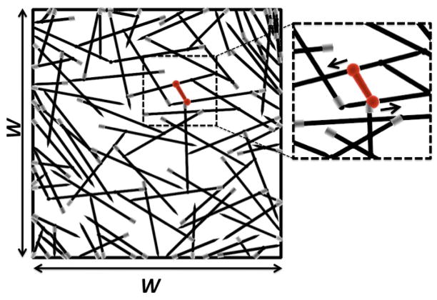
Our simulations build on the method of Ref. [13]. We first generate a two-dimensional random network, whose filaments represent either single actin filaments or parallel bundles of actin filaments. We place filaments with random positions and orientations in a 5μm × 5μm simulation cell (see Fig. 1). This size is likely an upper limit for biological relevance because localized adhesions pin the actin network to the substrate and thus act as rigid boundaries. Filaments extending outside the simulation cell are cropped. Static crosslinks are placed at filament intersections. Next the network is scanned for pairs of points on different filaments that could be linked by myosin minifilaments. At pairs of points whose distance is within 10% of the average equilibrium minifilament length L̄m, the two ends of a minifilament are placed and new, mobile crosslinks are created. This is the network’s equilibrium state in the absence of ATP-induced myosin motion.
FIG. 1.
Network as generated before relaxation. Region around minifilament (dumbbell) is enlarged and arrows show the direction of myosin motion (toward the barbed end). Arrowheads at ends of actin filaments represent pointed end; barbed end is drawn in grey. Here W = 5μm.
The system is then relaxed according to an energy function containing the stretching (Estretch) and bending (Ebend) energies of actin filaments and bundles, the minifilament stretching energy Em, and the ATP-driven motor energy Emotor moving myosin heads toward barbed ends. Estretch and Ebend are based on the lengths and relative angles of the filament segments between crosslinks (“rods”):
| (1) |
where μ is the stretching modulus, ΔLi is a rod’s length change, is its initial length, and Nr is the number of rods;
| (2) |
where κ is the bending modulus, Δθj is the angle between the two rods on the same filament meeting at the crosslink j, and L̄j is the average of the two rod lengths. Further,
| (3) |
where γ is a constant, and is the minifilament’s initial (final) length. Finally,
| (4) |
where Mj is the distance of myosin head j from the barbed end of its filament, in units of the step size δ, and FATP is the myosin stall force. At crosslinks, filaments rotate freely.
Although the method and results are broadly applicable, we consider the case of single (unbundled) actin filaments for concreteness. Then κ = kBTlp, where lp ≃ 15μm [14]. Because use of the experimental value of μ (45 nN [15]) leads to slow convergence of the elastic relaxation, we use a smaller value μ = 600 pN, which is still large enough that filament stretching is negligible compared to bending. We choose an actin filament length of 2 μm, based on typical values away from the leading edge of cells, and L̄m = 0.4 μm [1]; γ is varied over a range 60 – 120 pN/μm3. We vary FATP over a range on the order of pN, which corresponds to myosin heads with a low duty ratio.
We evolve each random network to a stable steady state minimizing the total energy Etot = Estretch + Ebend + Em + Emotor. Myosion motion is treated separately from elastic relaxation because it is slower. For each set of values of Mj, the elastic degrees of freedom are relaxed using a nonlinear conjugate-gradient method which gives finite (rather than infinitesimal) crosslink and minifilament displacements. The myosin heads then move via a steepest-descent algorithm driven by the derivatives ∂Etot/∂M1,2, until all of the forces have reached a specificed tolerance. Although the energies in the model are quadratic functions of Lm and Δθ, the energy-minimization solution can yield nonlinear displacements. We evaluate the spatially-averaged wall stress
| (5) |
where f⃗i is the force exerted by a rod on the wall, r⃗i is the position of a rod-wall contact point, and the sum is over all contact points. We make varying assumptions regarding the motion of myosin heads past crosslinks and at filament tips.
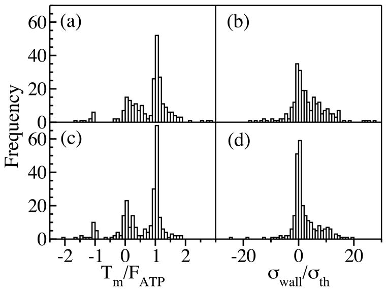
Fig. 2 shows the distributions of the minifilament tension Tm and σwall for the case where myosin heads reaching filament tips are pinned there. The wall tension is scaled by an elastic theory prediction σth = −2fd/πW2 obtained for a single small force dipole in a 2D circular isotropic elastic patch of area π(W/2)2 (see Supplementary Material at [URL will be inserted by publisher] for derivation). In a) and b), where myosin heads move past crosslinks, both Tm and σwall are overwhelmingly contractile. The values of Tm peak around the myosin stall force FATP. The fluctuations are caused by the varying angles between the minifilament and the actin filaments, and the pinning of minifilaments at filament tips. In c) and d), stopping myosin heads at crosslinks reduces the fraction of contractile configurations, but leaves the stress mainly contractile; the average Tm is reduced by about 50%. In both cases, the values of σwall sometimes exceed σth by as much as an order of magnitude. Allowing myosin heads to leave filament tips enhances the contractile stress by about 50%.
FIG. 2.
Distribution of minifilament tension (a,c) and wall stress (b,d). In a) and b) myosins jump over crosslinks; in c) and d) they are pinned. The mean wall stresses are 3.3σth and 2.0σth in (b) and (d) respectively. Positive values of Tm and σwall refer to contraction. Histograms obtained from 251 runs. Frame b) contains one more point at σwall ≃ 60σth, which was left out to improve visibility.
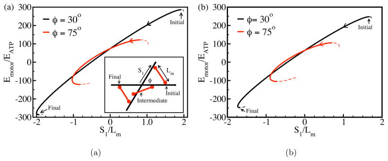
The reason for the dominance of contractile Tm values is seen most clearly when minifilaments come to equilibrium before reaching barbed ends. Contractile minifilament equilibria have lower energy than expansive ones. A minifilament which starts in an expansive-stress configuration tends to rotate and move until it reaches a stable contractile configuration. To clarify this effect, we consider a completely rigid minifilament, interacting with two rigid filaments at a relative angle of φ (see Fig. 3, inset) and distance of closest approach d (which vanishes in two dimensions). The only energy in this case is Emotor. Fig. 3 shows its variation as the minifilament moves from a symmetric equilibrium where it generates expansive stress. The motion is described in terms of S1,2, the positions of the ends of the minifilament relative to the crosslink (with the pointed-end direction taken positive); because Lm is fixed, S1 determines S2. Simple algebra shows that . This has two extrema, and the one with S1 > 0 (which causes expansive stress) is unstable, as indicated by the energy maxima at the two starting points in Fig. 3. From these local maxima, the minifilament rotates in either of two directions breaking the initial symmetry, indicated by the solid and dashed lines. After the minifilament has rotated far enough, both of its ends move in the barbed-end direction, and the minifilament reaches a stable contractile equilibrium. Comparison of Figs. 3(a) and 3(b) shows that this behavior persists in three dimensions. In our simulation results for minifilaments which equilibrated without becoming stuck, 61 of 62 runs resulted in contractile configurations like those of Fig 3a. In the sole exception, the minifilament stopped in an expansive-stress configuration because the two actin filaments that it impinged became bent enough to allow a local energy minimum.
FIG. 3.
Local equlibria of myosin minifilament moving between rigid actin filaments in two (a) and three (b) dimensions. Inset in (a) shows the geometry; barbed ends are at the left. Here EATP = δFATP, FATP = 1.9 pN, δ = 5.4 nm, Lm = 0.4 μm, and in frame (b) d = 0.2 μm. Solid lines denote path followed by minifilament; dashed lines denote another possible path.
This effect also implies that minifilaments which become stuck will often have rotated to contractile configurations before becoming stuck. A population of minifilaments starting with equal numbers of contractile and extensile members will then evolve into one biased toward contraction. Thus in 146 of the 188 runs with stuck minifilaments, Tm was contractile at the time of sticking, and all but 6 of these retained the contraction after complete relaxation. Of the remaining 42 runs, 27 transformed from extensile to contractile after sticking, by mechanisms including rotation with one end fixed.
The mechanism described here is quite general. It requires large rotations of myosin minifilaments, but not nonlinear actin network elasticity. Only 2% of the runs had extensile myosins with filament bending angles larger than 10°, showing that buckling is not a crucial factor. Furthermore, doubling the filament bending modulus κ, corresponding to reduced nonlinear effects, led to larger average values of Tm/FATP. The mechanism is also independent of specific assumptions regarding the behavior of myosin at filament ends. The main requirement for contractility is that the network structure be sufficiently rigid to support well-defined minifilament energy extrema. This requirement may explain why Ref. [2] found that crosslinkers were needed for contractility.
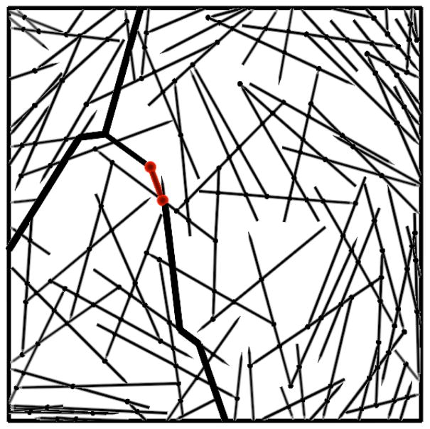
The very large wall stresses seen in Fig. 2 indicate the importance of the network structure. We find that tensile force chains - linked chains of rods under high stress - cause the stress enhancement. These are shown as the thick lines in the relaxed network of Fig. 4, which are obtained by finding all connected paths of rods having tensile strain exceeding a critical value of 0.01%. This mechanism is related to that of Ref. [7], in which force propagation along actin filaments connected to the minifilament enhances the stress; here the effect is greater because chains of filaments, rather than single filaments, are involved. The effect found here may help bridge the gap between measured values of the tension in cytokinesis, and the low theoretical values obtained in Ref. [7].
FIG. 4.
Force chain (thick lines) observed after elastic relaxation.
We have evaluated the robustness of the results by varying our input parameters and assumptions. The stresses increase sublinearly with increasing FATP, but remain contractile and greatly exceed σth. Doubling γ changes the mean stress by less than 1%; including a crosslink rotation energy comparable to the bending energy changes it by only about 5%. The mechanism is general enough to apply when dynamic network effects, such as actin filament treadmilling (barbed-end growth matched by pointed-end depolymerization) and crosslinker dynamics, are included. Since myosin heads move rapidly on actin filaments [16], the minifilaments would equilibrate in a few seconds or less. The time for a filament to treadmill is probably on the order at least tens of seconds. Typical crosslinker lifetimes in cells are on the order of tens of seconds [17, 18]. Therefore the qualitative conclusions reached here should be independent of treadmilling and crosslinker release.
In summary, directional motion of myosin minifilaments along actin network filaments, toward low-energy contractile configurations, produces contractile stresses. This general mechanism requires no specific orientation constraints in the network. Furthermore, the myosin stress is magnified by force chains which transmit force directly to the boundary. Future work should aim to evaluate the stresses more quantitatively in the context of a cellular environment incorporating a three-dimensional branched network structure.
Supplementary Material
Acknowledgments
This work was supported by the National Institutes of Health under Grant R01 GM086882.
References
- 1.Korn ED, Hammer JA. Annu Rev Biophys Biophys Chem. 1988;17:23. doi: 10.1146/annurev.bb.17.060188.000323. [DOI] [PubMed] [Google Scholar]
- 2.Bendix PM, Koenderink GH, Cuvelier D, Dogic Z, Koeleman BN, Brieher WM, Field CM, Mahadevan L, Weitz DA. Biophys J. 2008;94:3126. doi: 10.1529/biophysj.107.117960. [DOI] [PMC free article] [PubMed] [Google Scholar]
- 3.Thoresen T, Lenz M, Gardel ML. 2011 doi: 10.1016/j.bpj.2011.04.031. To be published. [DOI] [PMC free article] [PubMed] [Google Scholar]
- 4.MacKintosh FC, Levine AJ. Phys Rev Lett. 2008;100:018104. doi: 10.1103/PhysRevLett.100.018104. [DOI] [PubMed] [Google Scholar]
- 5.Mizuno D, Tardin C, Schmidt CF, MacKintosh FC. Science. 2007;315 doi: 10.1126/science.1134404. [DOI] [PubMed] [Google Scholar]
- 6.Chen P, Shenoy VB. Soft Matter. 2011;7:355. [Google Scholar]
- 7.Carlsson AE. Phys Rev E. 2006;74:051912. doi: 10.1103/PhysRevE.74.051912. [DOI] [PubMed] [Google Scholar]
- 8.Kruse K, Julicher F. Phys Rev Lett. 2000;85:1778. doi: 10.1103/PhysRevLett.85.1778. [DOI] [PubMed] [Google Scholar]
- 9.Kruse K, Julicher F. Phys Rev E. 2003;67:051913. doi: 10.1103/PhysRevE.67.051913. [DOI] [PubMed] [Google Scholar]
- 10.Zemel A, Mogilner A. Phys Chem Chem Phys. 2009;11:4821. doi: 10.1039/b818482h. [DOI] [PMC free article] [PubMed] [Google Scholar]
- 11.Lenz M, Dinner AR. arXiv:1101.1058 [physics.bio-ph] [Google Scholar]
- 12.Liverpool TB, Marchetti MC, Joanny JF, Prost J. Europhys Lett. 2009;85:18007. [Google Scholar]
- 13.Head DA, Levine AJ, MacKintosh FC. Phys Rev E. 2003;68:061907. doi: 10.1103/PhysRevE.68.061907. [DOI] [PubMed] [Google Scholar]
- 14.Koenderink GH, Dogic Z, Nakamura F, Bendix PM, MacKintosh FC, Hartwig JH, Stossel TP, Weitz DA. PNAS. 2009;106:15192. doi: 10.1073/pnas.0903974106. [DOI] [PMC free article] [PubMed] [Google Scholar]
- 15.Kojima H, Ishijima A, Yanagida T. Proc Natl Acad Sci. 1994;91:12962. doi: 10.1073/pnas.91.26.12962. [DOI] [PMC free article] [PubMed] [Google Scholar]
- 16.Diensthuber RP, Muller M, Heissler SM, Taft MH, Chizhov I, Manstein DJ. FEBS Lett. 2011;585:767. doi: 10.1016/j.febslet.2011.01.042. [DOI] [PubMed] [Google Scholar]
- 17.Fraley TS, Pereira CB, Tran TC, Singleton CA, Greenwood JA. J Biol Chem. 2005;280:15479. doi: 10.1074/jbc.M500631200. [DOI] [PubMed] [Google Scholar]
- 18.Vignjevic D, Kojima S, Aratyn Y, Danciu O, Svitkina T, Borisy GG. J cell Biol. 2006;174:863. doi: 10.1083/jcb.200603013. [DOI] [PMC free article] [PubMed] [Google Scholar]
Associated Data
This section collects any data citations, data availability statements, or supplementary materials included in this article.


