Abstract
We are interested in understanding the mechanisms behind and the character of the sway motion of healthy human subjects during quiet standing. We assume that a human body can be modelled as a single-link inverted pendulum, and the balance is achieved using linear feedback control. Using these assumptions, we derive a switched model which we then investigate. Stable periodic motions (limit cycles) about an upright position are found. The existence of these limit cycles is studied as a function of system parameters. The exploration of the parameter space leads to the detection of multi-stability and homoclinic bifurcations.
Keywords: human balance, switched systems, dynamics
1. Introduction
In spite of recent advances in revealing the mechanisms responsible for balancing during quiet standing (see [1–11]) the physiological mechanisms are far from being understood. In recent years, there has been a growing interest among scientists to use mathematical modelling and numerical simulations to gain new insights into the problem of balancing. In the literature, it has been argued that forward body sway can be captured using models where the muscles and tendon–muscle complexes act as springs with certain stiffness and the neuromuscular system generates the corrective torque [12–15]. Models based on these assumptions have been tested experimentally [8,12,13,16]. In the studies of Maurer & Peterka [8] and Peterka [16], a single-link inverted pendulum model with simple linear feedback was introduced. Different feedback laws were considered to obtain the best match to experimental data, and it was shown that a corrective torque proportional to the position and velocity signals combined with time delays can be used to account for the body sway observed experimentally.
Early work [17] suggested that intermittent control plays an important role in human motor control. Recent research [18,19] shows that intermittent control is a mechanism that can explain the results found in experimental tests. However, the authors also point out that there are alternative control models that can reproduce experimental results. Further research is needed to design experimental tests that can help to discriminate between different control models. An alternative model for human postural sway was considered in Eurich & Milton [20]. In this work, the authors use a reduced first-order model with a time-delayed feedback. In place of intermittent control, Eurich & Milton [20] consider a switched control system depending on a threshold for the angular position. For the first-order model, Eurich & Milton [20] show the existence of bi-stable limit cycles. In the study of Milton et al. [21,22], the switch-like balance controller was considered as a type of intermittent control. The idea of switched control was further explored in Milton et al. [23,24]. The authors considered a model with switched control, random perturbations that model noise, and time delay. It was shown that the interplay between noise and time delay may have a stabilizing property. The authors also argued that the control applied by humans is an adaptive switched control. The idea of switched control applied by humans during quiet standing serves as a starting point for the modelling approach adopted in this paper.
We approach the problem of human balancing by considering the subjects standing on both legs with eyes closed or open. We are interested in investigating the sway motion that occurs in the sagittal plane, i.e. we consider a forward–backward body sway.
The following assumptions are made:
— the body control is achieved using proprioception only (reception of internal signals such as posture and body sway through the length and elongation velocity of the muscles);
— we include time delays in the control system that represent the combined delays owing to sensory reception, neural transmission, neural processing, muscle activation and force development of the proprioception motor-neural control system;
— we exclude the control effects of exteroception (sensing of external signals such as pressure) and vestibular system (it senses the angular velocity and the acceleration of the head). We believe that an inclusion of these effects should yield additional terms in our model such as, for instance, force feedback or a control term proportional to the measured acceleration;
— we assume a threshold value of the angle of the sway below which the motor-neural control of the proprioception is not applied, similarly as in the work of Eurich & Milton [20]. This assumption is justified by the finite accuracy of sensing, as well as by the recent finding of impulsive like control muscle movements reported in Loram et al. [18];
— we assume that the motor-neural control of the musculoskeletal system when sensing the error works like a PD (proportional–derivative) control system with the time delay in the position and velocity error signals. The letter ‘P’ refers to the corrective torque that is proportional to the error signal between the desired angle θref (θref = 0 in our case) and the measured angle multiplied by the proportionality factor, say Kp, that can be thought off as a stiffness factor. The letter ‘D’ refers to the corrective torque that is proportional to the velocity of the error signal between the desired velocity of the angle
 (
( in our case) and the measured angular velocity with the proportionality factor, say Kd, that can be thought off as a damping factor.
Owing to the presence of a threshold value, our model is a hybrid (switched) system with time delay. The model we propose is similar to the one studied in Asai et al. [25]—the PD control is switched on or off depending on the value of state variables. The model studied in Asai et al. [25] is an extension of the studies conducted in Bottaro et al. [26,27] where the authors introduce intermittently switched on/off controller that allows for a bounded motion, and it is this type of control which Asai et al. [25] propose as the possible explanation for the sway motion during quiet standing. In the study of Asai et al. [25], it is also shown that the bounded dynamics is linked with a motion along the stable manifold of a saddle point. The control strategy used in Asai et al. [25] is based on the assumption that a bang–bang control does not allow sufficiently small bounded motion [27] to be produced, with the sway angle of about 1°, which could correspond to the sway motion during quiet standing. In our paper, we consider the simplest possible form of a dead zone, which is physiologically feasible, and we show in §4.4 that small scale stable periodic oscillations may be observed in bang–bang control systems in the presence of a dead zone.
We briefly summarize the results of our investigations. In order to maintain balance, the control of the proprioceptive system must use both: (i) the information on the elongation and (ii) the information on the velocity of the elongation of the muscles. This agrees with the fact that to stabilize an inverted pendulum (for small angles θ when the linear model of the pendulum is assumed) a linear controller must at least use the proportional and derivative signals of the error. Stabilization is achieved through the existence of stable oscillations about an offset angle ±θ0 where θ0 corresponds to the size of the dead zone. For a broad range of parameters, these oscillations are accompanied by stable larger scale oscillations. The difference in the amplitude of the angle of larger scale oscillations in relation to smaller scale oscillations is at least two orders of magnitude. In the context of upright standing, the small scale oscillations can be seen as a jitter about the nearly upright position; the ideal upright position cannot be achieved owing to our assumption that the motor-neural control of the musculoskeletal system only reacts to values larger than the aforementioned offset angle |θ0|, which is physiologically determined. By adding white noise to our model equations, we numerically show that close to a homoclinic bifurcation the system dynamics switches between two symmetric attractors. This scenario can explain noise-induced switchings between two coexisting attractors reported in Eurich & Milton [20]. Finally, we should note that multi-stability as well as the presence of periodic oscillations have already been reported in the literature on switched delay differential equations, see [28–31]. However, the delay differential equations studied in these works contain discrete time delay in the position feedback only.
The rest of the paper is outlined as follows. In §2, a class of systems of interest is introduced. The system without the time delay in control function is first studied in §3. We then go on to explore the effects of time delay on system dynamics in §4. In the following §5, we introduce the modifications to the model that will be tested in the future. Finally, §6 concludes the paper.
2. The model equations
We simplify the biomechanics of the body by representing it as an inverted pendulum with the body sway occurring in the sagittal plane about the ankle joint axis. Gravity g acts on the centre-of-mass when the angle θ (measured in radians) between the vertical ankle joint axis and the body's position becomes non-zero; when there is no sway the body is vertical and θ = 0. The centre-of-mass m is located at height h above the ankle joint axis.
We assume that to control the upright position a corrective torque T is applied through a PD controller when some fixed, but non-zero, positive threshold θ0 is detected.
This leads to the following model equations:
| 2.1 |
when there is no control applied to the system, and
| 2.2 |
when the PD control is switched on; J is the moment of inertia of the body about the ankle joint axis. The delay terms are present in the applied torque generated by the PD controller. Namely,
| 2.3 |
where Kp and Kd are negative constants, and Δ1, Δ2 > 0 are time delays.
We make a number of observations regarding the physical interpretation of the model. For |ϕ| ≤ ϕ0, the equations that govern system dynamics describe the dynamics of an inverted pendulum falling under the force of gravity. On the other hand, for |ϕ| > ϕ0, we have  . For Δ1 = Δ2 = 0 and sin(ϕ)≈ϕ, this equation is an equation of motion of a linear oscillator where the stiffness coefficient is given by (−Kp−mgh)>0 and the damping by −Kd>0. For Δ1 and Δ2 non-zero and positive, we obtain a second-order linear delay differential equation whose dynamics is significantly more complex than that of a second-order linear oscillator [32,33]. For sufficiently small Δ1 and Δ2, and under appropriate continuity assumptions, the dynamics of the delayed system can be studied using a set of ordinary differential equations (ODEs) [34]. However, the presence of switchings makes this reduction impossible even for small values of time delays.
Making the approximation sinϕ ≈ ϕ, which is justifiable for small angles ϕ of the body sway, the model equations (2.1) and (2.2) become
| 2.4 |
and
| 2.5 |
To reduce the number of parameters, we study system (2.4) and (2.5) in the non-dimensional form; we introduce the non-dimensional time  and set
  ,
,  . Then
  and
and  and we obtain
| 2.6 |
and
| 2.7 |
where  ,
,  , with B = hKp/gJ,
  ,
,  and
and  . In what follows, we drop the bar symbol when referring to non-dimensional time.
Setting  and using first-order representation, we arrive at a planar switched (Filippov) system of the form
 |
2.8 |
and
 |
2.9 |
where
 |
2.10 |
3. System dynamics for τ1 = τ2 = 0, and τ1 ≠ 0, τ2 = 0
3.1. Switched system with no time delays
We start our investigations by discussing the dynamics of switched systems (2.8) and (2.9) for τ1 = τ2 = 0. We first make the following observations:
— let x = (θ, x) then, by the symmetry, we have that −Fin(−x) = Fin(x) and −Fout(−x) = Fout(x);
— the integral curves of Fin are symmetric with respect to the θ and
 axes.
axes.
Second observation implies that if an integral curve of Fin crosses the switching line Σ1 at some point a ≠ 0 then it either crosses Σ1 = {θ = θ0}, at −a or Σ2 = {θ = −θ0} at a. Similarly, if we consider a ∈ Σ2 then the integral curve either crosses Σ2 at −a or Σ1 at a.
The only equilibrium of equations (2.8) and (2.9) is the origin or a pseudo-equilibrium. A pseudo-equilibrium of equations (2.8) and (2.9) is the equilibrium of the full systems (2.8) and (2.9) that lies on the switching line Σ1 or Σ2.
For A>0, the origin is an equilibrium of a saddle type characterized by the eigenvalues  and
and  with the associated eigenvectors
  and
and  .
.
Lemma 3.1. Consider equations (2.8) and (2.9) with A > 0, and B and C negative , and such that A + B < 0. Then the only equilibrium of equations (2.8) and (2.9) is the origin. There are also two accumulation points (pseudo-equilibria) which are located at (−θ0, 0) and (θ0, 0). The origin is an equilibrium of a saddle type and the pseudo-equilibria are the only two global attractors of equations (2.8) and (2.9). The basins of attractions of these two pseudo-equilibria are separated by the piecewise-smooth invariant manifolds of the saddle point of the full systems (2.8) and (2.9).
Proof. The first part of the lemma is trivial. The right-hand sides (RHSs) of equations (2.8) and (2.9) consist of sets of linear equations. If the determinants of matrix L given by equation (2.10) and the matrix
 |
are non-zero, which is true for A>0 and A + B<0, then the only possible equilibria are located at the origin. It is vector field Fin that is defined in the neighbourhood of the origin. Then for A>0, the equilibrium is of a saddle type as the eigenvalues of L are  and
and  . The only other possible equilibria are pseudo-equilibria which may only occur on the switching lines at points where the
  component of vector fields Fin and Fout is 0. It is easy to verify that this is the case only at (−θ0, 0) and (θ0, 0).
To prove the second part of the lemma, we first note that any point (θ, x) within the zone |θ|≤θ0 reaches some point on ± θ0 in finite time at some point, say P1. Let us suppose that P1 lies on the positive part of Σ1. From P1, the flow follows the flow generated by Fout until some point P2 ∈ Σ1 is reached. The equations of motion along this segment of the flow are given by
Let  and set
  and multiply both sides by
  . We then have
Thus, P2 must be closer to the origin than P1. From P2, the flow follows
Using the energy argument again, and owing to the fact that Σ1 and Σ2 are placed the same distance away from the origin, the energy at the next point of switching with Σ1 or Σ2 is the same as at P2. There is a loss of energy only owing to the application of the flow Fout and after subsequent switches between Fin and Fout the trajectory will converge to either of the two pseudo-equilibria since at these two points the system Fout reaches its lowest energy.
Finally, to determine which pseudo-equilibrium is reached, we have to find the intersection points of the unstable and stable manifolds of the saddle point with Σi (i = 1,2). Concatenated segments joining subsequent intersection points form piecewise-smooth stable and unstable manifolds. By considering the evolution of a single trajectory, we can then show that the trajectory will be moving within a region bounded by the stable and unstable manifolds of the saddle point until it reaches either one of the two pseudo-equilibria. Owing to system's symmetry if some point Pin converges to (θ, 0) then −PIn will converge to −(θ, 0).
Illustrative trajectory of switched systems (2.8) and (2.9) with A = 0.5, B =−0.6, C =−0.5, θ0 = 1 and the initial conditions (θ0, x0 ) = (1,0.4) is depicted in figure 1.
Figure 1.
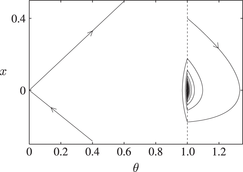
Illustrative trajectory of switched systems (2.8) and (2.9) for A = 0.5, B = −0.6, C = −0.5, θ0 = 1 and the initial conditions (θ0, x0 ) = (1,0.4) converging to a pseudo-equilibrium (θ 0, 0). The eigenvectors are depicted as solid lines.
If A + B < 0 and C is identically 0, it is easy to verify that our system exhibits an infinite number of periodic orbits which can be thought of as centres. Two representative periodic orbits for this case are depicted in figure 2.
Figure 2.
Periodic solutions of equations (2.8) and (2.9) for A = 0.5, B =−0.6 and C = 0 with no time delay, i.e. τ1 = τ2 = τ = 0; (a) the initial conditions (θ0, x0) = [3,0], and (b) (θ0, x0) = [1.3,0].
If, on the other hand, B = 0 and C < 0 then the system trajectories will diverge to ± ∞.
We conclude this section with the physical interpretation of our results. When both the proportional and derivative control are applied instantaneously (no time delay owing to sensing, processing and actuation) then provided that A + B < 0 it is possible to achieve perfect stabilization. However, the angle θ at which the body is stabilized is offset from the vertical angle θ = 0.
3.2. Effects of the damping term and the position delay (τ1 ≠ 0 and τ2 = 0)
Our model system can be thought of as a generalization of the model studied by Eurich & Milton [20]. In this work, the authors model human postural sway using a second-order ODE, which models inverted pendulum falling under the force of gravity, subject to time-delayed restoring force and noisy perturbation. Using an assumption that the postural sway is overdamped, for healthy subjects with eyes open, they reduce their model to a first-order system. Our numerics suggest that this reduction removes stable pseudo-equilibria present in the second-order system. Thus, the reduced system does not have the possibility of producing multi-stable behaviour in the sense of having more than one pair of stable asymmetric orbits; by the system's symmetry stable asymmetric orbits come in pairs.
We observed the existence of stable pseudo-equilibria in equations (2.8) and (2.9) with (2.8) having additionally a damping term  . The switched system studied in this paper with the additional
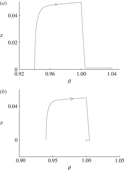
  term in equation (2.8), and with τ2 = 0, can be thought of a system with damping and delayed position feedback and it is then the full model system studied in Eurich & Milton [20]. Numerical results with B varied and fixed A = 0.5, C = −10, time delay τ1 = 0.2 and τ2 = 0 are shown in figure 3. In figure 3a, for B = −0.49, the pseudo-equilibrium located at (1,0) is unstable. We depict a representative diverging trajectory. A trajectory converging to a stable pseudo-equilibrium, existing for B = −0.51, is depicted in figure 3b. The parameters are chosen so that the postural sway is overdamped. Reduction of this system to the first order will remove the possibility of having a stable pseudo-equilibrium; the stable state may be of physiological importance.
Figure 3.
(a) Diverging trajectory in the switched systems (2.8) and (2.9), modified by adding  within the dead zone, for A = 0.5, B =−0.49 and C =−0.1; time delay τ1 = 0.2, τ2 = 0. The initial history segment for the trajectory (for t ∈ [−τ, 0]) is set to a constant value: θ(t) = 0.94 and x(t) = 0. (b) Transient trajectory for B = −0.51 and other parameters as in (a) converging to a stable pseudo-equilibrium located at (1,0). The initial history segment for the trajectory (for t ∈ [−τ,0]) is set to a constant value: θ(t) = 0.94 and x(t) = 0.
4. Effect of time delay in the PD control
Time delay enters the model through the delay present in the PD controller. We assume that the time delay coming from the position and velocity signals are equal, that is, τ1 = τ2 = τ. This simplifying assumption is justified because in reality, we encounter distributed delays and there is no evidence that the delay coming from the position signal is significantly longer or shorter than the delay of the velocity signal.
To reduce the size of parameter space, for all our numerical experiments, we assume θ0 = 1. This assumption can be made without loss of generality as shown in appendix A.1.
4.1. Characteristic equation of the delay system
In order to understand the dynamics of our model, we have to understand the effects of time delay on the dynamics of the control system (2.9). We can rewrite equation (2.9) as a second-order linear retarded differential difference equation. We have
| 4.1 |
Let  , where
  is an arbitrary but non-zero constant. Then, equation (4.1) becomes
| 4.2 |
Equation (4.2) is the characteristic equation of the retarded differential difference equation (4.1). The eigenvalue solutions λ of this equation determine the character of the solutions of equation (4.1).
4.2. Dynamics for B = 0 and τ small, and for C = 0 and τ small
Let us consider system dynamics when C = 0 and τ is small. Then the characteristic equation (4.2) becomes
| 4.3 |
For τ = 0, we obtain a system that conserves energy, and the eigenvalues of the characteristic equation of the ODE that governs system dynamics are  . For τ sufficiently small, we calculate the dominant eigenvalues of the characteristic equation (4.3) by expanding it in τ. We then have
and after rearrangement we get
| 4.4 |
Approximating the RHS of equation (4.4) to zero the roots of the quadratic equation (4.4) are
By assumption B < 0, (A + B) < 0, and hence if τ > 0 and is sufficiently small there are at least two roots of equation (4.4) with positive real parts. This implies further that in the current case the trajectories of systems (2.8) and (2.9) will diverge to infinity for τ sufficiently small. A representative trajectory for this scenario is depicted in figure 4 with the parameters set to A = 0.5, B = −0.6, C = 0 and time delay τ = 0.1.
Figure 4.
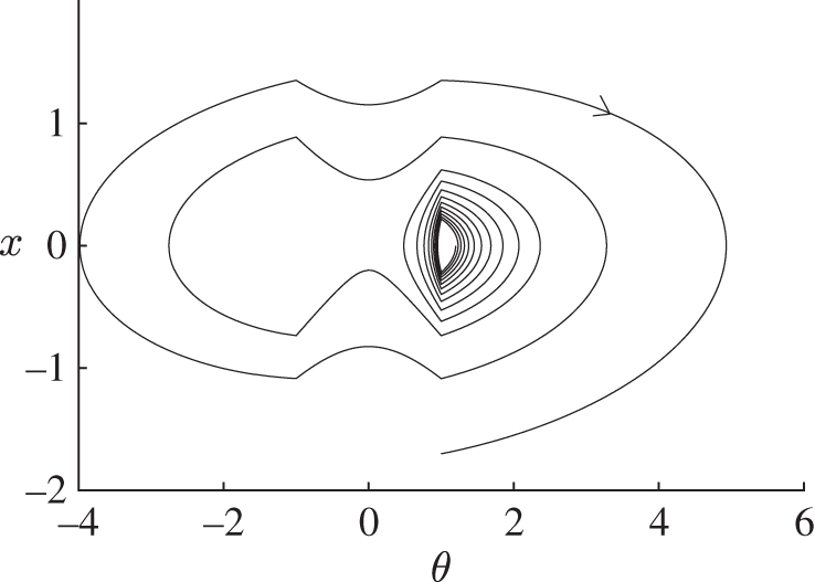
Representative trajectory of the switched systems (2.8) and (2.9) for A = 0.5, B =−0.6 and C = 0; time delay τ = 0.1. The initial history segment for the trajectory (for t ∈ [−τ, 0]) is set to a constant value: θ (t) = 1.2 and x(t) = 0.
We can similarly derive the approximate characteristic equation when B = 0 and C < 0, and argue that trajectories will diverge to infinity for τ sufficiently small.
To conclude
— if the derivative control is not active (C = 0: the damping term not present) or if the proportional control is not active (B = 0: no additional stiffness), and the time delay is small enough, the switched systems (2.8) and (2.9) is not controllable, and all the trajectories diverge to ± ∞;
— numerics suggests that the above scenarios persist also for large values of τ.
4.3. Switched PD control: B and C non-zero
To create a stable limit cycle, it is necessary to move all the eigenvalues of the characteristic equation (4.2) to the left half-plane of the complex plane. Assume that both τ and C are small, that is both τ and C are 𝒪(ɛ). To leading order in τ and C the characteristic equation (4.2) is
| 4.5 |
The two roots of the quadratic equation (4.5) are
 |
4.6 |
For C and τ sufficiently small these roots are complex conjugate, and it is the sign of the real part, that is the sign of C − Bτ, which determines whether all the roots of the characteristic equation (4.2) lie in the left half-plane of the complex plane.
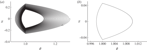
Considering the previous numerical example if we set C =−0.07, we expect that a system trajectory will converge to an attractor since then C − Bτ < 0, and the dominant eigenvalues lie in the left half-plane of the complex plane. This is indeed the case as depicted in figure 5.
Figure 5.
(a) A trajectory converging to an attractor of the switched systems (2.8) and (2.9), for A = 0.5, B =−0.6 and C =−0.07; time delay τ = 0.1, and (b) the attractor.
In figure 6, we depict a diverging trajectory of equations (2.8) and (2.9) for A = 0.5, B =−0.6, C =−0.05 and the time delay τ = 0.1. Hence the condition C − Bτ < 0 is violated and there exist eigenvalues of the characteristic equation (4.5) with a positive real part.
Figure 6.
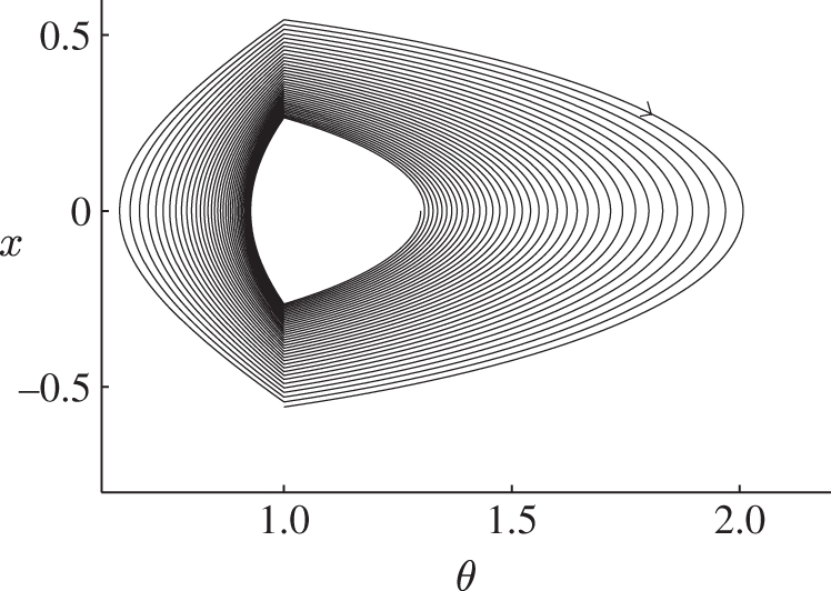
A diverging trajectory of the switched systems (2.8) and (2.9) for A = 0.5, B =−0.6 and C = −0.05; time delay τ = 0.1.
We should make a comparison here between our switched model and the delay differential equation that governs system dynamics outside of the dead zone. Assuming there is no dead zone (ideal sensing of the proprioceptive system) then the small scale stable oscillations present in the switched system correspond to the stable equilibrium states of the delay system. If, on the other hand, there are no attractors present in the switched system then the equilibrium of the delay system must be unstable, and the asymptotic dynamics of the switched and delay systems can be considered equivalent (the trajectories diverge to ± ∞).
4.4. Multiple stable oscillations
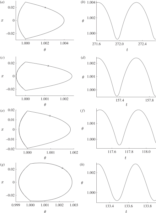
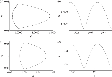
Having established the existence of stable periodic oscillations in our model, we wish to examine the region of parameter space where these oscillations persist, and also, what are the parameter values that are critical for the onset of different asymptotic dynamics. Initially, we set the parameters to these values for which we found stable limit cycles in §4.3; we set τ = τ1 = τ2 = 0.1, A = 0.5, B =−0.6, and we vary C. In figure 7a–h, we are depicting representative limit cycles and corresponding time series for C ∈ [−10, −0.1]. We note that there is little effect of the variation of C on the amplitude and the period of the oscillations for C ∈ [−10, −0.2] (figure 7c–h). When we vary C between −0.2 and −0.1, we observe that the value of  at the switching between Fin and Fout increases from around 0.02 to 0.03 and the period from 0.5 to 0.7 (cf. figure 7c,d with figure 7a,b). To sum up, the effect of the variation of C on the existing periodic orbits is more pronounced for small values of C and there is little effect of the variation of C on the periodic orbits for −10 < C < −0.2.
Figure 7.
(a) Periodic orbits of the switched system (2.8) and (2.9) for A = 0.5, B =−0.6, C = [−0.1(a), −0.2; (c), −1; (e), −10(g)] and the corresponding time series in (b), (d), (f) and (h). Time delay τ = 0.1.
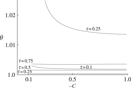
To further investigate the system numerically, we obtained one-parameter orbit diagrams on which we depict the variation of a periodic point on the attractor versus parameter −C for distinct values of the time delay τ (figure 8). We found the coexistence of two families of attractors. Namely, we observe stable oscillations, e.g. figure 7a–h that coexist with stable oscillations of different period and amplitude. Note two curves obtained for τ = 0.25 one in a close proximity of x1 = 1 and the other further away from x1 = 1.
Figure 8.
One parameter orbit diagrams capturing two families of periodic attractors. One family is characterized by negligible change in the amplitude for C ∈ [−0.1, −1] (the values of τ are given to the left of the curves); the second family is characterized by a pronounced change in the amplitude for the values of C close to −0.1 (the values of τ are given above the curves).
We found the coexistence of these two families of attractors also for τ = 0.5 and τ = 0.75 (not depicted in the figure). We conjecture that these two families of attractors are born in the limit as τ → 0. Their presence is due to the switched nature of the system. Representative examples of two coexisting attractors, each corresponding to one family of periodic orbits, found for τ = 0.25 are depicted in figure 9. The amplitude θ, say Amp(θ), of the limit cycle in figure 9c is Amp(θ) ≈ 0.02. This is about 50 times larger than Amp(θ) of the limit cycle in figure 9a. The period of the limit cycle in figure 9c is about 1.2 which is approximately six times longer than the period of the limit cycle in figure 9a; cf. the time series in figure 9d,b.
Figure 9.
Coexisting stable limit cycles and corresponding time series of the switched systems (2.8) and (2.9) for A = 0.5, B = −0.6 and C = −0.5. Time delay τ = 0.25.
4.5. Homoclinic bifurcations and bi-stability
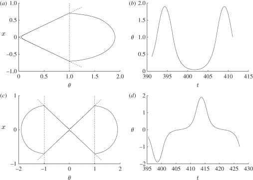
Another important feature of our system is the birth of stable symmetric orbits with long period through so-called homoclinic bifurcation. This phase space transition takes place under increasing values of τ when the switching between Fin and Fout occurs at points on Σ1 where the eigenvectors corresponding to the saddle point cross Σ1.
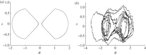
Consider oscillations depicted in figure 10. Note that within the dead zone the orbit from figure 10a existing for A = 0.5, B =−0.6, C =−1 and τ = 1.1135 is very close to the stable and unstable manifolds of the saddle point (note the dashed lines in the figure superimposed on the orbit). For τ = 1.114 this orbit no longer exists, instead a stable symmetric orbit born in the homoclinic bifurcation is present (figure 10c). A homoclinic orbit existing at the bifurcation is formed from the stable and unstable manifolds of the saddle point. Within the dead zone, the shape of the orbit is given by the straight lines lying along the eigen-directions of the saddle point and outside of it by the arches joining these straight lines. In other words, it is the stable and unstable manifolds that form a homoclinic orbit, and any trajectory starting its evolution on the orbit stays on it and reaches an unstable equilibrium of the saddle type in infinite time. This in turn implies that the periods of the orbits ‘before’ and ‘after’ the bifurcation are long—see time series in figure 10b,d, respectively. The straight lines emanating from the origin refer to the stable and unstable eigen-directions of the saddle point. We believe that it is the homoclinic bifurcations that allow for the noise-induced switchings between two coexisting attractors reported in Eurich & Milton [20]. We note that sufficiently close to the bifurcation there exist two stable asymmetric attractors as depicted in figure 11a. If we add white noise to the system then a typical trajectory will evolve around these two attractors as depicted in figure 11b. In the latter case, the switched systems (2.8) and (2.9) becomes a stochastic switched system with time delay, and its evolution within the dead zone is governed by
 |
4.7 |
and outside of the dead zone by
 |
4.8 |
where σ is the intensity of the applied white noise ζ (t). The parameter values are set to A = 0.5, B =−0.6, C = −1, σ = 0.1 and τ = 1.112. Both figures were generated using the first-order Euler method with step size Δt = 0.001. The numerical integration scheme used to produce figure 11b is described in the appendix.
Figure 10.
Homoclinic bifurcation for A = 0.5, B =−0.6, C =−1; (a) ‘before’ the bifurcation for τ = 1.1135, in (b) we depict the corresponding time series, and (c) after the bifurcation for τ = 1.114, in (d) we depict the corresponding time series.
Figure 11.
(a) Periodic attractors close to a homoclinic bifurcation of the switched system (2.8), and (b) a typical trajectory of the switched systems (4.7) and (4.8) with added white noise.
5. Modifications to the model
The investigations described here serve as an initial step to gain insight into the dynamics of upright balance. There is a number of modifications that could be considered to gain more insight into the problem of balancing. In the first instance, we could alter the model with the dead zone and time delay to a model with time delay and delay in the switching function. This modification reflects our assumption on the presence of time delay in the neural transmission and muscle activation when switching the PD control. In this paper, we consider the simplest possible model and that is why the dead zone is fixed. This can also be seen as modelling the time delay in the neural transmission only. In some papers, it is also argued that there is a time delay in the acceleration terms (see [35]). It could be also interesting to compare different control strategies and stable states that these can produce. Finally, we would like to develop the model to include the mechanism(s) of muscle tiring. This we believe to be a crucial element in the loss of balance in elderly people.
There are also other important issues. Namely, the dynamics of a multiple link inverted pendulum model could be more realistic. These modifications will be pursued in collaboration with experimentalists who work on human balance.
At this point, we would like to comment on the correspondence between the dimensional and non-dimensional quantities of our model system. For example, if we take physiologically feasible values, similar to those used in Asai et al. [25], and set m = 60 kg, h = 1 m, g = 9.81 m s−2, J = 60 kg m2, time delay Δ1 = Δ2 = 0.1 s, the width of the dead zone |θ| = 0.02 rad, and the control coefficients Kp = 720 Nm rad−1, KD = 60 Nms rad−1 our non-dimensional quantities are equal to A = 0.0001, B = 0.00012, C = 0.0031 and the time delay τ = 31. Our numerical simulations show that for these parameter values the system exhibits stable pseudo-equilibria. We should note that these values are in a different regime from the one we explored numerically. The reason for our numerical exploration is that we want to discover all, or as much as possible, of qualitatively different dynamics that can be found in our model system. Having found multi-stability, small scale periodic oscillations, and a homoclinic bifurcation, all of which can be potentially important for human balance, it now remains to validate which of these scenarios can, indeed, be observed in experiments. This implies further that it may be necessary to use additional tools from dynamical systems analysis, for instance a numerical continuation of bifurcation curves, to obtain an exhaustive picture of the dynamics of the model system for parameter values which are physiologically feasible. However, this last point must be informed by experiments.
6. Conclusions
In this paper, we introduce a model of human balance during quiet standing following the idea that a human body can be modelled by a single-link inverted pendulum, and balance is achieved using linear feedback control with time delay in the proportional and derivative error signals. We assume a threshold value of the angle of the sway below which the motor-neural control system cannot detect any sway motion. We obtain a planar switched (hybrid) model. We find that to achieve stabilization, which is seen as ‘small’ oscillations about an upright equilibrium, it is necessary that both the proportional and derivative signals of the control system are used. These stable oscillations seem to represent closer to observation stable state for upright standing than the equilibrium points [23]. Therefore, we study the effects of parameter variations on their existence.
Our parameter study leads to the detection of a multiple number of stable oscillatory states existing for the same parameter values and for a wide range of the control parameters corresponding to the derivative term of the PD controller. We also find a homoclinic bifurcation that gives birth to a stable symmetric orbit with a long period. In particular, we show, using a numerical experiment, that close to a homoclinic bifurcation white noise introduced additively may result in the system switching between the two regions where symmetric stable solutions exist in the deterministic switched system leading to an apparent bi-stability; in other words, the switched system with added noise evolves for some time in the neighbourhood of each one of the two stable asymmetric limit cycles (present in the deterministic system) by switching between their regions of existence. This scenario can explain switchings between a pair of stable asymmetric attractors observed in the first-order model in Eurich & Milton [20], which in turn was used to explain different scaling patterns that could be detected in human postural sway data.
Obviously, an important step in the investigations of human balance would be verification of the stable oscillatory states found in our model system. In particular, it would be interesting to see if, indeed, we can observe small scale oscillations close to an equilibrium against the larger scale stable oscillations and how are these linked with the physiology of human subjects.
Acknowledgements
Research partially funded by Engineering and Physical Sciences Research Council grant EP/E050441/1 (CICADA: Centre for Interdisciplinary Computational and Dynamical Analysis), the University of Manchester and Manchester Metropolitan University.
Appendix A
A.1. Model scaling
Consider the system for k > 0 given by
 |
A 1 |
which is our standard control model with dead zone |θ| ≤ k. We aim to show that this is equivalent (after scaling) to a model with dead zone |θ| ≤ 1 of the form
 |
A 2 |
Thus having a smaller dead zone (smaller k) corresponds, in systems rescaled so that the dead zone is constant, to having a larger relative dissipation but a longer delay time; i.e. the effect is not obvious (larger relative dissipation implies greater stability, longer delay implies less stability). Note that the time t in the second equation is not the same as the time t in the first equation.
To see this, we will start from equation (A 2) and derive (A 1). First, let ψ(t) = kθ(t), so |θ| ≤1 becomes |ψ| ≤k and dψ/dt = k(dθ/dt) and (A 2) becomes
 |
A 3 |
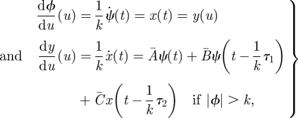
Now introduce a new time variable u = kt, and let ϕ(u) = ψ(t), and y(u) = x(t). Note that
| A 4 |
and similarly for y(u). Moreover
and so using equation (A 3)
 |
A 5 |
with a simpler equation if |ϕ| ≤k. Finally, using the definitions of ϕ and y, and the shift rule (A 4) gives (with primes denoting differentiation with respect to u)
 |
A 6 |
which is equation (A 1) after the identifications ϕ → θ, y → x and u → t.
A.2. Euler's method for the switched system with the time delay and white noise
Switched systems (4.7) and (4.8) is a stochastic system with switching and time delay. The angle θ and the angular velocity  are now random variables. The presence of the switching function implies that depending on the value of the random variable θ system equation is governed by a stochastic differential equation, or a stochastic delay differential equation. We switch between these two systems when the random variable θ is greater or smaller than the threshold value θ0. It has been shown in the study of Kloeden & Platen [36] that stochastic delay differential equations
| A 7 |
where τ is the time delay, ζ(t) is Gaussian white noise with intensity σ, can be approximated by
| A 8 |
for h sufficiently small; τ is the time delay, h is the step size, k = τ/h and Wn is the standard Wiener process. Similarly, a stochastic differential equation
| A 9 |
can be approximated by a discrete system
| A 10 |
Above numerical scheme was used to generate the trajectory of the stochastic switched systems (4.7) and (4.8). Switching occurs at the integration step n when θn − θ0 changes sign. The standard Wiener process is approximated numerically at each step tn by a function that generates pseudo-random numbers with expected value μ = E[X] = 0 and standard deviation  , where X is a random variable.
References
- 1.Loram I. D., Maganaris C. N., Lakie M. 2009. Paradoxical muscle movement during postural control. Med. Sci. Sports Exerc. 41, 198–204. 10.1249/MSS.0b013e318183c0ed ( 10.1249/MSS.0b013e318183c0ed) [DOI] [PubMed] [Google Scholar]
- 2.Loram I. D., Lakie M., Di Gulio M. D., Maganaris C. N. 2009. The consequence of short range stiffness and fluctuating muscle activity for proprioception of postural joint rotations: the relevance to human standing. J. Neurophysiol. 102, 460–474. ( 10.1152/jn.00007.2009) [DOI] [PubMed] [Google Scholar]
- 3.Loram I. D., Lakie M., Gawthorp P. J. 2009. Visual control of stable and unstable loads: what is the feedback delay and extent of linear time-invariant control? J. Physiol. 587, 1342–1365. 10.1113/jphysiol.2008.166173 ( 10.1113/jphysiol.2008.166173) [DOI] [PMC free article] [PubMed] [Google Scholar]
- 4.Di Gulio M. D., Maganaris C. N., Baltzopoulos C. N., Loram I. D. 2009. The proprioceptive and agonist roles of gastrocnemius, soleus, and tibialis anterior muscles in maintaining human upright posture. J. Physiol. 587, 2399–2416. 10.1113/jphysiol.2009.168690 ( 10.1113/jphysiol.2009.168690) [DOI] [PMC free article] [PubMed] [Google Scholar]
- 5.Peterka R. J. 2002. Sensorimotor integration in human postural control. J. Neurophysiol. 88, 1097–1118. [DOI] [PubMed] [Google Scholar]
- 6.Peterka R. J., Loughlin P. J. 2004. Dynamic regulation of sensorimotor integration in human postural control. J. Neurophysiol. 91, 410–423. 10.1152/jn.00516.2003 ( 10.1152/jn.00516.2003) [DOI] [PubMed] [Google Scholar]
- 7.Jeka J., Kiemel T., Creath R., Horak F., Peterka R. 2004. Controlling human upright posture: velocity information is more accurate than position or acceleration. J. Neurophysiol. 92, 2368–2379. 10.1152/jn.00983.2003 ( 10.1152/jn.00983.2003) [DOI] [PubMed] [Google Scholar]
- 8.Maurer Ch., Peterka R. J. 2005. A new interpretation of spontaneous sway measures based on a simple model of human postural control. J. Neurophysiol. 93, 189–200. 10.1152/jn.00221.2004 ( 10.1152/jn.00221.2004) [DOI] [PubMed] [Google Scholar]
- 9.Cenciarini M., Peterka R. J. 2006. Stimulus-dependent changes in the vestibular contribution to human postural control. J. Neurophysiol. 95, 2733–2750. 10.1152/jn.00856.2004 ( 10.1152/jn.00856.2004) [DOI] [PubMed] [Google Scholar]
- 10.Goodworth A. D., Peterka R. J. 2009. Contribution of sensorimotor integration to spinal stabilization in humans. J. Neurophysiol. 102, 496–512. 10.1152/jn.00118.2009 ( 10.1152/jn.00118.2009) [DOI] [PMC free article] [PubMed] [Google Scholar]
- 11.Goodworth A. D., Peterka R. J. 2010. Influence of stance width on frontal plane postural dynamics and coordination in human balance control. J. Neurophysiol. 104, 1103–1118. ( 10.1152/jn.00916.2009) [DOI] [PMC free article] [PubMed] [Google Scholar]
- 12.Gatev P., Thomas S., Kepple T., Hallett M. 1999. Feedforward ankle strategy of balance during quiet stance in adults. J. Physiol. 514, 915–928. 10.1111/j.1469-7793.1999.915ad.x ( 10.1111/j.1469-7793.1999.915ad.x) [DOI] [PMC free article] [PubMed] [Google Scholar]
- 13.Winter D. A., Patla A. E., Prince F., Ishac M., Gielo-Perczak K. 1998. Stiffness control of balance in quiet standing. J. Neurophysiol. 80, 1211–1221. [DOI] [PubMed] [Google Scholar]
- 14.Winter D. A., Patla A. E., Riedtyk A. E., Ishac M. 2001. Ankle muscle stiffness in the control of balance during quiet standing. J. Neurophysiol. 85, 2630–2633. [DOI] [PubMed] [Google Scholar]
- 15.Masani K., Popovic M. R., Nakazawa K., Kouzaki K., Nozaki D. 2003. Importance of body sway velocity information in controlling ankle extensor activities during quiet stance. J. Neurophysiol. 90, 3774–3782. 10.1152/jn.00730.2002 ( 10.1152/jn.00730.2002) [DOI] [PubMed] [Google Scholar]
- 16.Peterka R. J. 2003. Simplifying the complexities of maintaining balance. IEEE Eng. Med. Biol. Mag. 22, 63–68. ( 10.1109/MEMB.2003.1195698) [DOI] [PubMed] [Google Scholar]
- 17.Craik K. 1947. Theory of the human operator in control systems. I. The operator as an engineering system. Br. J. Psychol. 38, 56–61. 10.1111/j.2044-8295.1947.tb01141.x ( 10.1111/j.2044-8295.1947.tb01141.x) [DOI] [PubMed] [Google Scholar]
- 18.Loram I., Gawthrop P., Lakie M. 2006. The frequency of human, manual adjustments in balancing an inverted pendulum is constrained by intrinsic physiological factors. J. Physiol. 557, 417–432. 10.1113/jphysiol.2006.118786 ( 10.1113/jphysiol.2006.118786) [DOI] [PMC free article] [PubMed] [Google Scholar]
- 19.Loram I., Gollee H., Lakie M., Gawthrop P. 2011. Human control of an inverted pendulum: is continuous control necessary? Is intermittent control effective? Is intermittent control physiological? J. Physiol. 589, 307–324. 10.1113/jphysiol.2010.194712 ( 10.1113/jphysiol.2010.194712) [DOI] [PMC free article] [PubMed] [Google Scholar]
- 20.Eurich Ch., Milton J. 1996. Noise-induced transitions in human postural sway. Phys. Rev. E 54, 6681–6684. 10.1103/PhysRevE.54.6681 ( 10.1103/PhysRevE.54.6681) [DOI] [PubMed] [Google Scholar]
- 21.Milton J., Cabrera J., Ohira T. 2008. Unstable dynamical systems: delay, noise and control. EPL 83, 48001. 10.1209/0295-5075/83/48001 ( 10.1209/0295-5075/83/48001) [DOI] [Google Scholar]
- 22.Milton J., et al. 2009. Balancing with vibration: a prelude for ‘drift and act’ balance control. PloS ONE 4, e7427. 10.1371/journal.pone.0007427 ( 10.1371/journal.pone.0007427) [DOI] [PMC free article] [PubMed] [Google Scholar]
- 23.Milton J., Cabrera J. L., Ohira T., Tajima S., Tonosaki Y., Eurich C. W., Campbell S. A. 2009. The time-delayed inverted pendulum: implications for human balance control. Chaos 19, 026110. [DOI] [PubMed] [Google Scholar]
- 24.Milton J., Townsend J. L., King M. A., Ohira T. 2009. Balancing with positive feedback: the case for discontinuous control. Phil. Trans. R. Soc. A 367, 1181–1193. 10.1098/rsta.2008.0257 ( 10.1098/rsta.2008.0257) [DOI] [PubMed] [Google Scholar]
- 25.Asai Y., Tasaka Y., Nomura K., Nomura T., Casadio M., Morasso P. 2009. A model of postural control in quiet standing: robust compensation of delay-induced instability using intermittent activation of feedback control. PLoS ONE 4, e6169. [DOI] [PMC free article] [PubMed] [Google Scholar]
- 26.Bottaro A., Casadio M., Morasso P., Sanguineti V. 2005. Body sway during quiet standing: is it the residual chattering of an intermittent stabilization process? Hum. Mov. Sci. 24, 588–615. 10.1016/j.humov.2005.07.006 ( 10.1016/j.humov.2005.07.006) [DOI] [PubMed] [Google Scholar]
- 27.Bottaro A., Yasutake Y., Nomura T., Casadio M., Morasso P. 2008. Bounded stability of the quiet standing posture: an intermittent control model. Hum. Mov. Sci. 27, 473–495. 10.1016/j.humov.2007.11.005 ( 10.1016/j.humov.2007.11.005) [DOI] [PubMed] [Google Scholar]
- 28.an der Heiden U., Longtin A., Mackey M., Milton J., Scholl R. 1990. Oscillatory modes in a nonlinear second order differential equation with delay. J. Dyn. Diff. Equ. 2, 423–449. [Google Scholar]
- 29.an der Heiden U., Richard M. 1992. Multitude of oscillatory behaviours in a nonlinear second order differential-difference equation. J. Appl. Math. Mech. 70, 621–624. [Google Scholar]
- 30.Bayer W., an der Heiden U. 2007. Delay-differential equations with discrete feedback: explicit formulae for infinitely many coexisting periodic solutions. J. Appl. Math. Mech. 87, 471–479. 10.1002/zamm.2002.10329 ( 10.1002/zamm.2002.10329) [DOI] [Google Scholar]
- 31.Bayer W., an der Heiden U. 1998. Oscillation types and bifurcations of a nonlinear second-order differential-difference equation. J. Dyn. Diff. Equ. 10, 303–326. 10.1023/A:1022670017537 ( 10.1023/A:1022670017537) [DOI] [Google Scholar]
- 32.Stépán G. 1990. Retarded dynamical systems: stability and characteristic functions. New York, NY: Longman Scientific and Technical. [Google Scholar]
- 33.Hale J. K., Lunel S. M. V. 1993. Introduction to functional differential equations. New York, NY: Springer. [Google Scholar]
- 34.Chicone C. 2003. Inertial and slow manifolds for delay equations with small delays. J. Diff. Equ. 190, 364–406. 10.1016/S0022-0396(02)00148-1 ( 10.1016/S0022-0396(02)00148-1) [DOI] [Google Scholar]
- 35.Lockhart D., Ting L. 2007. Oscillatory modes in a nonlinear second-order differential equation with delay. Nat. Neurosci. 10, 1329–1336. 10.1038/nn1986 ( 10.1038/nn1986) [DOI] [PubMed] [Google Scholar]
- 36.Kloeden P. E., Platen E. 1995. Numerical solution of stochastic differential equations. Berlin, Germany: Springer. [Google Scholar]


