Abstract
Pelvic floor disorders (PFD) affect one of every four women in the United States. Elevated intra-abdominal pressure (IAP) during daily activity or strenuous physical activity has been identified as a risk factor in the prevalence of PFD. However, the relationship between IAP and physical activity is poorly understood and oftentimes activity restrictions are prescribed by physicians without clinical evidence linking various activities to elevated IAP. There are currently no pressure transducers capable of monitoring IAP non-invasively out of a clinical environment. To overcome this shortcoming, a novel intra-vaginal pressure transducer (IVT) was developed to continuously monitor IAP. Improvements were made to the first generation IVT by incorporating wireless capability to enhance the device’s mobility while creating a more robust IAP monitoring system. To ensure the changes maintained the functionality of the original device design, comparison testing with standard clinical pressure transducers in both bench top and clinical settings was conducted. The wireless device was found to have high linearity, robust signal transmission, and dynamic response that outperforms the clinical standard rectal transducer and is similar to the original first generation non-wireless design. The wireless IVT presented here is a mobile wireless device capable of measuring, storing and transmitting IAP data during various physical activities.
Keywords: Pressure transducer, Pressure sensor, Intra-abdominal pressure, Vaginal transducer, Frequency response, Dynamic response, Physical activity
1 Introduction
According to a 2005–2006 National Center for Health study, nearly 24% of U.S. women are affected with a primary or recurrent pelvic floor disorder (PFD). Female pelvic floor disorders have been referred to as a hidden epidemic by clinicians in the United States (Hendrix et al. 2002; Nygaard et al. 2008). They often result from a weakening of the pelvic floor muscles and cause lifestyle altering symptoms such as incontinence and pelvic organ prolapse in which women experience herniation of the pelvic viscera such as the bladder, uterus and rectum into the vaginal cavity. The pathophysiology of PFD is unclear. One proposed disease mechanism, which lacks clinical support, is the increased load to the pelvic floor in the form of elevated intra-abdominal pressure (IAP) during physical activity. This lack of clinical understanding motivates the need to investigate the role that elevated IAP plays in the progression, recurrence and incidence of PFDs during exercise and activities of daily living.
Physiologic pressure measurement systems typically employ electromechanical transducers that convert pressure into an electrical signal that can be processed, displayed and stored. Historically, devices that have been used to develop clinical standards for such measurements utilize micromachined silicon piezoresistive sensors which have high accuracy, small size and low cost. A variety of medical devices have been developed utilizing piezoresistive sensor technology to monitor intracranial (Minns 1984), arterial (Kinefuchi et al. 1994), urethral (Perucchini et al. 2002), and gastrointestinal (Fang et al. 2004) physiologic pressures.
Transducers based on microelectromechanical systems (MEMS) for physiologic pressure monitoring are used in conjunction with wireless telemetry techniques to transfer pressure data taken within the body to an externally located receiver (Tan et al. 2009). Telemetry systems are available from several manufacturers for both clinical and research use. One commonly available wireless system consists of an implanted sensor and external receiver in which internal power provides high data bandwidth at ranges of 0.2–5 m (www.datasci.com). This wireless scheme requires internal batteries which need to be recharged or replaced and oftentimes contribute to a larger implant size. Other wireless strategies utilize a passive telemetry approach for power and data transfer. These systems employ electromagnetic coupling and utilize backscatter amplitude modulation to detect signal changes (DeHennis and Wise 2005). Passive telemetry systems oftentimes have a smaller footprint and have increased implanted lifetime due to inductive power coupling. Other systems based on passive telemetry systems use coupled inductors where the sensor is passively powered by the receiver. In this system, the sensor oscillates as a function of pressure altering the frequency of the transmitted signal (Fonseca et al. 2006). Passive telemetry systems are approved by the FDA for use in endovascular monitoring (www.medscape.com). To date the fully implantable pressure sensors have only been developed for monitoring pressure in a fluid filled environment such as in vascular applications and are not suitable for measurements in body cavities such as the vagina or rectum.
Historically, intra-abdominal pressure measurement devices are classified as sensor-tipped catheters or fluid-coupled transducers. Sensor-tipped catheters are designed to place the sensor, located at the catheter tip, directly at the physiologic site of interest. Although, sensor tipped catheters are more accurate than fluid-coupled transducers (Stoker 2004), they require a fluid filled environment, such as the bladder or urethra, to achieve adequate and reliable pressure measurements. In a non-fluid filled space, such as the vagina or the rectum, the location and orientation of the sensor-tipped catheter can drastically alter the pressure readings (Holt et al. 1990; Perucchini et al. 2002). To overcome this shortcoming, sensor-tipped catheter systems are typically employed in the bladder but bladder fluid volume must be tightly controlled making IAP monitoring during daily activity impractical (Malbrain 2004).
Fluid coupled transducers utilize non-compressible fluids, such as saline, to transmit pressure from the physiologic site of measurement to an externally located sensor. These systems typically deploy inflated balloons which allow pressure measurements to be made in non-fluid filled environments such as the vagina or rectum. Due to the distance of the sensor from the pressure source, the fluid filled tubing that conveys the pressure signal can have a substantial effect on the measurement accuracy (Hunziker 1987; Hundley et al. 2006). Additionally, damping and resonance effects of these systems are dependent on component characteristics such as the length, diameter and stiffness of the tubing connecting the sensor to the site of measurement (Stoker 2004). Other factors such as air bubbles in the line can cause erroneous pressure measurements (Malbrain 2009). Nonetheless, this technique is preferable for measuring IAP during static conditions such as under standard urodynamic laboratory testing. However, care must be taken to interpret the data and understand the limitations of these systems due to poor dynamic response during rapid changes in pressure (Johnson et al. 2009).
The inadequacies of current pressure transducers have hampered our understanding of the relationship between IAP during activities of daily living and pelvic floor disorders. To overcome these shortcomings, our lab developed a proof-of-principle intravaginal transducer (IVT) that measured IAP using a piezoresistive sensor at the site of physiological measurement. The generation 1 device (Gen1) consisted of a silicone elastomer bullet-shaped outer capsule with integrated electronic components mounted on a custom printed circuit board (PCB). The PCB electronic components included a pressure sensor die, resistor and a signal amplifier sealed in the elastomeric capsule. Prior to use, the capsule was filled with sterile water which served as the transduction medium to couple the sensor die to external forces applied to the capsule. Bench top testing and preliminary human trials demonstrated that the Gen1 device had improved performance over the “gold standard” rectal balloon transducer in its ability to accurately measure rapid changes in pressure needed for real-world IAP measurements (Johnson et al. 2009).
The goal of the project described in this paper was to design a second generation (Gen2) IVT pressure sensor capable of wirelessly monitoring IAP during daily activity. The first generation proof-of-principle IVT was designed to address many user needs such as user comfort, retention and accurate IAP monitoring (Johnson 2009; Rosenbluth et al. 2010). The Gen1 device however did not allow user mobility, lacked on-board calibration and required filling with water prior to use. Design modifications to the first generation devices were incorporated to address these problems while maintaining retention and comfort. The incorporation of the wireless technology required that pressure measurements be accurately recorded, stored and transmitted to the base station receiver. In addition, the wireless device needed to be comfortable to wear, retained during physical activities and easily removable. Here we report on the design, bench testing and preliminary in vivo evaluation of the wireless second generation IVT. This new design will allow for accurate intra-abdominal pressure measurements during routine daily activities outside of a clinical setting.
2 Materials and methods
The design strategy of the Gen2 device was to incorporate a microsensor, signal conditioner, microcontroller, power supply, and supporting wireless components into a gel filled elastomeric capsule. Wireless technology requirements were specified by the FCC Medical Device Radio communications Service (MedRadio). User safety, comfort, retention, and accuracy of intra-abdominal pressure measurement guided additional design requirements.
2.1 Capsule design
The analog Gen1 IVT was packaged in the Rev1 capsule that was modeled after female hygienic devices and consisted of a cylindrical elastomeric capsule measuring 27.4 mm in length, 12.7 mm in diameter and ending in a rounded terminus. To incorporate proposed wireless components while preserving retention and performance characteristics, modifications to the original capsule design were needed. The final capsule design (Rev4) consisted of a large diameter base of 23.9 mm tapering to 14.7 mm diameter at the distal terminus with an overall length of 37.3 mm. Capsules were injection molded using machined aluminum molds with silicone elastomer (MED-4940, Nusil) cured at 150°C for 5 min.
2.2 Microsensor package design and assembly
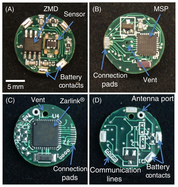
Space limitations of the capsule and size of electronic components required the electronic circuitry be separated into two electronic circuit boards. The insertable medical device (IMD) board side A (Fig. 1(a)) consisted of a pressure sensor (gauge-type microsensor—3SC 2000 IT, Merit Sensor Systems), signal processor (ZMD31014GID1, ZMD International Inc.) and four large solderable pads for attachment of the brass battery contacts. The battery contacts supplied power and ground from the coin cell battery while providing structural support to the electronics package. IMD side B (Fig. 1(b)) consisted of a MSP430 series microcontroller (MSP430F2132TRHBT, Texas Instruments) with 512 B onboard RAM for data buffering. Additionally, side B contained eight connection pads that served as the communication link between the IMD board and RF board through eight 34 gauge magnet wires (34 MAG, All Spectrum Electronics).
Fig. 1.
Photograph of circuit boards and main features for wireless Gen2 circuitry. The IMD side A (A) contains the piezoresistive pressure sensor, ZMD signal processor and battery contacts. IMD side B (B) contains the MSP430 microcontroller and eight connection pads for linking the IMD board to the RF board. RF side A (C) contains the Zarlink wireless chip and connection pads. RF side B (D) contains four communication lines for programming and calibration and battery contacts
The radio frequency (RF) board side A (Fig. 1(c)) consisted of eight connection pads for communication with the IMD board and a Zarlink wireless chip (ZL70101LGD1, Zarlink). Wireless communication was achieved by utilizing the ISM radio band 402–405 MHz channel that is allocated for medical device communication by the FCC (wireless.fcc.gov). Side B of the RF board (Fig. 1(d)) consisted of matching RF network, antenna, and four connection pads for temporary attachment of communication wires for programming and calibration. As with the IMD board, power to the RF board was supplied through four brass contacts from the battery.
A piezoresistive pressure die was secured to the prepopulated IMD electronics board with a small amount of UV-cure adhesive (3311, Loctite) to one corner of the die. The sensor die was microbonded to the IMD board mating pads using a manual wirebonder (West Bond 7476D-79) with aluminum 1% silicon 75 μm diameter bonding wire (CFW0014026, California Fine Wire). The sensor die and bonded wires were sealed and reinforced using a small amount of UV-cure alkoxy silicone (5248, Loctite).
The battery holder provides a structural frame that secures the IMD, battery, and RF circuit board into an electronics package able to fit within the capsule. An assembly drawing of the electronics package is shown in Fig. 2. A knife plotter (Cutting Pro FC7000-75, Graphtec) was programmed to cut out an array of battery protectors from a 0.010″ polyester sheet as designed in a 2D computer-aided design CAD program (AutoCAD 2010, Autodesk). Each battery protector was separated from the sheet, folded around a 16 mm diameter aluminum rod and secured using UV-cure adhesive (3311, Loctite). Battery contacts were measured and cut from .006 in. thick brass shim stock. A short circuit protector was made using .002 in. polyester along with a knife plotter and CAD software. Once cut, the short protector was placed over the negative terminal of the coin cell battery (CR1632, Panasonic) preventing the brass shim stock from simultaneously contacting both the positive and negative terminals. A contact protector was designed to prevent electronic components on the circuit boards from contacting the battery and was made using .010″ thick polyester sheet. Battery contacts were threaded though the precut slits of the battery protector securing the battery in the holder. The battery contacts were bent to accommodate both RF and IMD circuit boards in subsequent assembly steps. Contact protectors were placed at each end covering the brass contacts at both ends. Clear polyester shrink tubing .002″ thick (789200CST, Advanced Polymers) was cut to length and placed around the battery protector, heated, and secured in place around the outside of the battery holder.
Fig. 2.
Assembly drawing of electronic package. The battery is held in place by the four battery contacts. The contact protector at each end prevents the battery contacts from interfering with the IMD and RF circuit boards. Absent from this drawing are the shrink tubing, coaxial cable, and interboard communication wires
A vent tube 0.027″ outside diameter 0.001″ wall thickness (Polyimide, Small Parts) was cut to length and threaded through the vent hole on the circuit board along with 0.2″ of exposed strain relief filament from the tether. UV-cure adhesive (3311, Loctite) was used to secure both the vent tube and strain relief to RF circuit board. The vent tube was then threaded through the hollow portion of the strain relief tether. The tether consisted of an extruded silicone elastomer with incorporated nylon filament. A coaxial cable (SMA RG-178, Digikey) was soldered to the RF electronics board. A patch antenna (ZLE70101BADA, Zarlink) was then attached to the coaxial cable prior to use.
Circuit boards were prepopulated on both sides with all components including the microbonded sensor die. Solderable magnet wire (34 AWG, All Spectrum Electronics) was cut to length and soldered into via holes on the IMD circuit board side B. The magnet wire was threaded through the side wall between the battery and the battery protector and soldered to the corresponding pads on the RF circuit board side A. The battery contacts were folded making contact with the power pads located on IMD board side A and RF board side B and soldered. Once assembly of the electronics package was complete, four 32 gauge wires (32 AWG flex wire, Daburn) were soldered onto the programming pads on the RF board.
2.3 Final transducer assembly
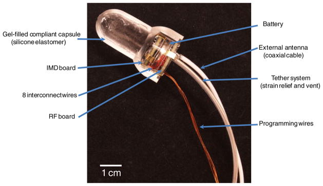
Wireless devices were assembled by first pre-filling elastomeric capsules with silicone gel (MED6350, Nusil) and degassing the gel in a vacuum at −22 inHg. The IMD board side A and RF board side B PCBs were primed using a silicone primer (MED1-161, Nusil) and dried for 30 min at room temperature to improve the adhesion of the silicone gel and elastomer. The electronics package was then pressed into the capsule until no air bubbles were observed. The silicone gel and electronic package was cured in place at 70°C for 30 min. Silicone elastomer was used to pot the end of the capsule using an injection mold system. The devices were then allowed to cure at 150°C for 10 min. A cross-sectional view of the completed sensor design (absent elastomer potting and patch antenna) is shown in Fig. 3.
Fig. 3.
Photograph displaying a cross section of the wireless intravaginal transducer. A coin cell battery is sandwiched between the IMD and RF circuit boards. The clear battery holder houses the electronics and battery in place supported by brass battery contacts. Four programming wires allow for programing and calibration. These wires are removed after calibration and prior to final device assembly. The tether is used for device retrieval and serves as an atmospheric vent. An coaxial cable allows attachment of an external antenna
2.4 Wireless prototype bench testing
Programming and calibration of wireless Gen2 IVT prototypes was achieved through a four-wire JTAG connection using an interface board, MSP430 debugger (MSP-FETU430IF, Texas Instruments) and a computer. The IVT was sealed in a pressure chamber allowing the vent tube to be exposed to atmospheric pressures. Sensor output of three parameters: atmospheric offset, gain, and temperature coefficient of offset (TCO) were needed for calibration. To obtain the atmospheric offset counts, the ZMD signal processor averaged pressure counts of the Wheatstone bridge for 5 s at a frequency of 30 Hz. Next, gain was obtained by pressurizing the vessel to 5 psi (350 cm H2O) using a NIST traceable reference transducer (Testcom, ER3000) at room temperature and averaging the pressure counts for 5 s at 30 Hz. The TCO was calculated by calibrating the ZMD internal thermistor at room temperature and at 37°C at atmospheric pressure. The offset of the sensor was normalized by setting 0 psi to 8,192 counts and gain set to 16,383 counts at 5 psi (350 cm H2O).
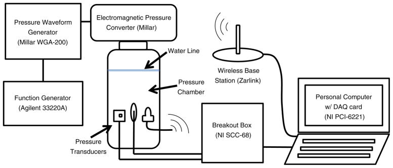
A pressure chamber was built to test the impulse and frequency response of the wireless Gen2 IVT as shown in Fig. 4. The vessel consisted of a clear PVC pipe (2 3/4″ OD×2 1/2″ ID×6″, US Plastics) sealed to a PVC threaded cap (PVC 2″ threaded cap, US Plastics) and adaptor (PVC 2″ male adapter, US Plastics) with plastic adhesive (Scotch-Grip 4475, 3 M). A multifunction pressure waveform generator (WGA-200, Millar Instruments) was connected to an electromagnetic pressure converter (Millar Instruments) mounted atop the airtight compartment. The pressure waveform was controlled by a function generator (33220A, Agilent Technologies). A conventional blood pressure transducer (Intran, Utah Medical) was modified to expose the gel-filled pressure aperture directly to the water in the chamber. The blood pressure transducer, Gen2 IVT and rectal balloon catheter (CAT509, Laborie Medical) were all threaded through a hole in three stopcocks and sealed in designated holes in the threaded cap. The rectal balloon catheter was filled with deionized water until air bubbles were eliminated and was subsequently connected to a second blood pressure transducer. The testing vessel was filled with deionized water. Using the function generator, a swept sine wave and impulse (square wave) tests were performed to analyze the dynamic response of the transducers according to industry guidelines (ANSI/ AAMI 1994/(R)2006). Reference and rectal balloon transducer outputs were recorded at 1,000 Hz and stored using a breakout box (SCC-68, National Instruments), a DAQ card (PCI-6221, National Instruments), and a custom LabView 8.0 program. Measurements were converted from voltage to pressures using the calibration transfer function and filtered with a 10-sample moving average. Wireless Gen2 IVT outputs were recorded at 30 Hz and stored using a Zarlink ADK base station and computer.
Fig. 4.
Dynamic response test setup. All three pressure transducers were sealed in the pressure chamber. (from left to right: reference transducer, rectal balloon catheter and wireless Gen2 IVT)
2.5 Wireless prototype clinical testing
After obtaining study approval from the University of Utah Health Sciences Center Institutional Review Board, informed consent was collected from seven volunteers undergoing standard urodynamic testing. A sterile wireless Gen2 IVT and standard rectal balloon catheter was placed in each study participant by a member of the clinical research team. Each participant performed a series of coughs followed by a Valsalva maneuver both in the seated and standing position. Rectal balloon IAP readings were recorded at 15 Hz using clinical cystometry software (Laborie Medical Technologies) under a standard bladder volume of 200 ml. Wireless IVT pressure measurements were taken at 30 Hz using the Zarlink ADK base station and custom laptop software. Results of each transducer were plotted and compared.
3 Results
3.1 Wireless prototype bench testing
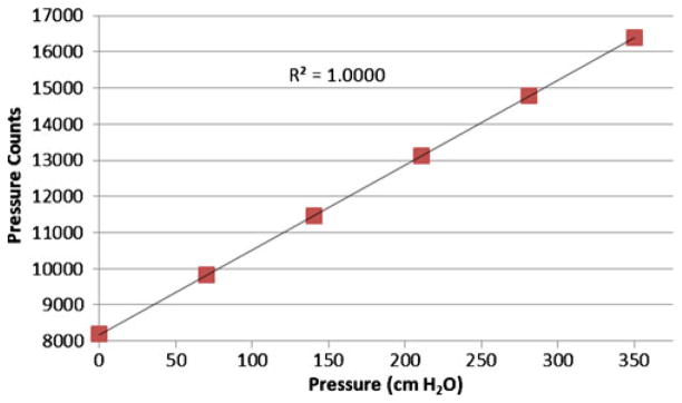
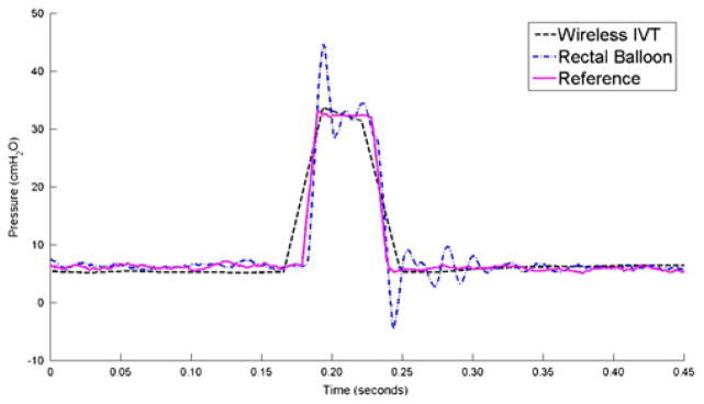
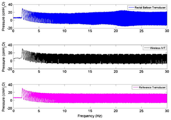
The gel-filled wireless GEN II IVT was calibrated using the ZMD signal conditioner to have an average count of 8,192 at 0 cm H2O and 16,383 counts at 350 cm H2O. The calibrated sensor demonstrated a highly linear response (R2=1.0000) from 0 to 350 cm H2O and a sensitivity of 23.44 counts/cm H2O (Fig. 5). The dynamic performance of the gel-filled IVT is shown by the impulse response test shown in Fig. 6. The fluid-coupled rectal balloon catheter exhibited a response typical of an underdamped second-order system. An overshoot of 35% was measured from the balloon catheter’s response to an impulse pressure input. An overshoot of 2% was measured during the same test from the Gen2 IVT. The swept sine wave test results (Fig. 7) show a resonant frequency with the rectal balloon catheter but not with the reference transducer or Gen2 IVT. The natural frequency, Fn, of the rectal balloon catheter was calculated to be 24.6 Hz and the damping coefficient, D, was calculated to be 0.30 exemplifying a highly underdamped system (AAMI 1992). The flat bandwidth (15% tolerance) of the balloon catheter was determined to be 15 Hz from the swept sine wave results. Flat bandwidth is defined as the range of frequencies starting at 0 Hz at which accurate measurements are obtained (AAMI 1994). Natural frequencies and damping coefficients for the Gen2 IVT were incalculable with no measured overshoot in swept sine wave tests.
Fig. 5.
Calibration curve for wireless Gen2 IVT
Fig. 6.
Results of three transducers during an impulse response test
Fig. 7.
Swept sine wave frequency plot for three transducers
3.2 Wireless IVT clinical evaluation
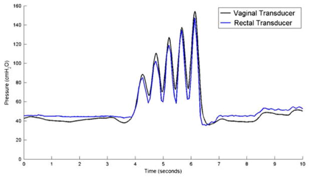
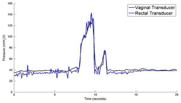
Wireless Gen2 devices capsules were tested against a conventional urodynamics balloon catheter placed in the rectum. Pressure measurements made by the wireless Gen2 IVT were consistent with rectal catheter data in both coughs (Fig. 8) and Valsalva maneuvers (Fig. 9).
Fig. 8.
IAP measurement while subject coughs 4 times
Fig. 9.
IAP measurement while subject performs a Valsalva maneuver
4 Discussion
The Gen2 IVT is a significant step towards our goal of developing a device to continuously monitor IAP during daily activity. The improvements made to the first generation IVT include the integration of a silicone gel, onboard calibration, and wireless technology. Modifications to the original design were tested against standard clinical devices to ensure device performance and data integrity. Wireless technology allows users free mobility while providing the clinician accurate IAP monitoring during daily activities. It is through this monitoring that clinicians can begin to study the relationship between intra-abdominal pressure (IAP) and the progression of pelvic floor disorders in a real world setting.
4.1 Capsule design and electronics package
Capsule size and shape was influenced by the size of electronic components, user retention, and device performance. The gel-filled portion of the elastomeric capsule acted as the transfer medium to couple external forces applied to the capsule to the sensor die.
The integration of a signal conditioner, microcontroller and wireless components allow the wireless Gen2 IVT to be calibrated, packaged, sterilized and stored prior to use. The ZMD uses a CMOS amplification and analog-to-digital conversion unit for bridge input signals. This analog-to-digital output converts output voltage from the sensor into pressure counts. Each count represents a specific pressure and is compensated for offset and the temperature coefficient of offset (TCO) using a built in thermistor and internal digital correction algorithm. The ZMD signal conditioner communicates with the MSP430 microcontroller through the I2C digital output pins allowing programming and calibration coefficients to be controlled exclusively through the MSP430. The MSP also serves as a temporary data storage unit for pressure counts which is cleared once a wireless session is established between the Gen2 IVT and the base station. The MSP includes 8 KB + 256 B flash memory with 512 B RAM storage capacity and is compatible with I2C communication and synchronous SPI protocol for communication with the Zarlink wireless chip.
The RF board consists of the Zarlink wireless chip and matching RF antenna network. Each wireless Gen2 IVT is flashed with a unique identifier that allows for device initialization by activation of the 2.54 GHz wakeup signal sent by the base station. The wakeup signal initializes the MSP and ZMD to wake-up out of low power mode to start data acquisition. As pressure measurements are recorded the MSP temporary memory will start to fill with pressure counts. Once a session is negotiated between the base station and the Zarlink wireless chip, a wireless data packet consisting of the pressure counts in the MSP buffer is sent to the base station utilizing the 400–404 MHz transmission band. The transfer of the wireless packet clears the buffer in the MSP allowing it to be refilled with pressure counts. Ideally, a wireless session between the base station and the Gen2 IVT will occur every 1.5 s sending one wireless packet consisting of 45 pressure counts. The wireless packet received by the base station contains header information that denotes device status, temperature and error messages followed by relative time stamps assigned to each pressure count.
4.2 Calibration and dynamic response
The ZMD signal conditioner converts output voltage of the sensor into pressure counts. Calibration of the Gen2 IVT eliminates offset of the sensor by adjusting the ZMD output to 8,192 counts at 0 cm H2O. Temperature coefficient of offset is compensated allowing the ZMD to output 8,192 counts at 0 cm H2O at a temperature of 37°C. The wireless Gen2 IVT is programmed to utilize half the ZMD resolution and outputs 16,383 counts at 350 cm H2O or 23 counts/cm H2O. If necessary the ZMD can be configured to utilize the full resolution of the device by setting the pressure counts to 0 at 0 cm H2O and 16,383 counts at 350 cm H2O or 47 counts/cm H2O. The requirements of the IVT specified an accuracy of 1% of full range (full range = 350 cm H2O) and therefore using half the headroom of the ZMD counts was sufficient for the performance of this device.
Comparing the dynamic response of the wireless IVT to the Utah Medical reference transducer showed no resonance effects during the swept sine test. The rectal balloon catheter accurately tracked pressure during gradual pressure changes (i.e. low dP/dt) less than 15 Hz when compared to the reference transducer. However, during abrupt pressure changes (i.e. high dP/dt) above 15 Hz, resonance effects were seen in which flat bandwidth tolerance is exceeded by the transducer. These results were further demonstrated during the impulse response test where the wireless IVT showed little overshoot while the rectal balloon catheter recorded a 35% overshoot in pressure when compared to the reference. These results are typical of an underdamped (D < 1) pressure measurement system where fluid inertia, tubing compliance and viscous effects contribute to the error during abrupt pressure changes (Stoker 2004). The sampling rate of the wireless IVT is optimally set at 30 Hz to adequately capture IAP changes during exercise while conserving battery life. The 30 Hz sampling rate resulted in aliasing effects in the wireless IVT during the swept sine wave test and impulse response test, both of which were not observed in the rectal balloon or reference transducers sampled at 1,000 Hz. Despite the aliasing effects, no resonance characteristics were observed during the wireless dynamic response test, a result that is supported by previous bench testing on analog devices (Coleman et al. 2010). Oscillations in pressure during baseline and swept sine wave tests were observed in the Gen2 IVT. These oscillations were between 1 and 2 cm H2O in amplitude and occur at regular intervals of 1.5 s, corresponding to a wireless data packet transmission. These dips in pressure measurement are a result of a slight power drain in the electronic circuitry but are not observed to exceed the AAMI standard of 15% flat bandwidth tolerance (AAMI 1992). A downward drift in pressure was observed in all transducers in the frequency range of 0–5 Hz. This drift is attributed to an insufficient seal in the test vessel, initially forcing air out of the system during testing. At the conclusion of each test the baseline pressure returned to pre-test levels.
Drift of atmospheric pressure measurements have been observed during post calibration and post sterilization readings of the wireless IVT (data not shown). To combat the day to day drift in atmospheric baseline, sensor readings are taken prior to human use to establish the atmospheric baseline pressure reading. Subsequent data analysis corrects for the positive or negative offset change by referencing all subsequent pressure measurements to atmosphere. Further studies are needed to characterize drift over time.
4.3 Clinical measurement
Wireless Gen2 devices showed equivalent IAP tracking when compared to rectal balloon catheter in-vivo. True IAP pressures are obtained directly in the peritoneal cavity, a challenging and highly invasive measurement which is unreasonable for the purposes of our study. We chose to compare the wireless IVT response to the clinical standard IAP transducer, the rectal balloon catheter. During activities with gradual pressure changes such as Valsalva maneuvers and isolated coughs both transducers were found to be comparable. This study did not investigate exercise activities such as jumping or running, which exhibit rapid changes in IAP pressure, because study participants were clinical patients undergoing a standard urodynamic study. However, past urodynamic studies showed rapid changes in IAP, associated with jumping, resulted in pressure overshoot of the rectal balloon catheter that was not observed in the first generation IVT (Johnson 2009). Therefore, we believe the IVT proves a more accurate account of IAP during rapid pressure changes useful in measurement of women undergoing a broad range of activities in a real-world setting. This conclusion is supported by the impulse and swept sine wave tests.
5 Conclusion
The results of this study demonstrate the ability of the wireless Gen2 IVT to accurately and reliably measure intra-abdominal pressure when compared to the reference and rectal balloon catheters. The improvements to the first generation design were validated using both bench top and clinical testing. The integration of an on-board signal conditioner allows the atmospheric and temperature offset to be compensated while applying the gain (sensitivity). Wireless technology allows the versatility of free movement within the laboratory setting while establishing the foundation for future development of the Wireless Remote Abdominal Pressure System (WRAPS). Future development will focus on creating an on-person base station receiver with micro SD memory storage allowing for continuous “real world” IAP tracking. Long term measurements during “real world” activities and exercise will provide researchers and clinicians with valuable information regarding the load profile on the pelvic floor and the correlation with the incidence, progression and reoccurrence of pelvic floor disorders.
Acknowledgments
The authors would like to thank Srivastsav Venkatesan and Arun Kandi for their assistance with software development of the wireless Gen2 IVT. The project described was supported by Award Number R01HD061787 from the Eunice Kennedy Shriver National Institute of Child Health and Human Development. The content is solely the responsibility of the authors and does not necessarily represent the official views of the Eunice Kennedy Shriver National Institute of Child Health and Human Development or the National Institutes of Health.
Abbreviations
- IAP
Intra-abdominal pressure
- PFD
Pelvic floor disorders
- IVT
Intravaginal transducer
- WRAPS
Wireless remote abdominal pressure system
Contributor Information
Tanner J. Coleman, Department of Bioengineering, University of Utah, 20 S. 2030 E, Rm. 186, Salt Lake City, UT 84112, USA
Jens C. Thomsen, Department of Electrical Engineering, University of Utah, 20 S. 2030 E, Rm. 186, Salt Lake City, UT 84112, USA
Sean D. Maass, Department of Bioengineering, University of Utah, 20 S. 2030 E, Rm. 186, Salt Lake City, UT 84112, USA
Yvonne Hsu, Department of Obstetrics and Gynecology, University of Utah School of Medicine, 30 N. 1900 E., Rm 2b200, Salt Lake City, UT 84132-2101, USA.
Ingrid E. Nygaard, Department of Obstetrics and Gynecology, University of Utah School of Medicine, 30 N. 1900 E., Rm 2b200, Salt Lake City, UT 84132-2101, USA
Robert W. Hitchcock, Email: r.hitchcock@utah.edu, Department of Bioengineering, University of Utah, 20 S. 2030 E, Rm. 190C, Salt Lake City, UT 84112, USA
References
- AAMI. Association for the Advancement of Medical Instrumentation AAMI TIR No.9. 1992. [Google Scholar]
- AAMI. Association for the Advancement of Medical Instrumentation BP22. 1994. [Google Scholar]
- ANSI/AAMI (BP22:1994/(R) Blood Pressure Transducers. 2006. [Google Scholar]
- Coleman TJ, Hsu Y, et al. IEEE. 2010. [DOI] [PubMed] [Google Scholar]
- DeHennis AD, Wise KD. J Microelectromech Syst. 2005;14(1):12–22. [Google Scholar]
- Fang JC, Hilden K, et al. Digest Dis Sci. 2004;49(10):1657–1663. doi: 10.1023/b:ddas.0000043382.59539.d3. [DOI] [PubMed] [Google Scholar]
- Fonseca MA, Allen MG, et al. 2006 [Google Scholar]
- Hendrix SL, Clark A, et al. Am J Obstet Gynecol. 2002;186(6):1160–1166. doi: 10.1067/mob.2002.123819. [DOI] [PubMed] [Google Scholar]
- Holt PE, Gibbs C, et al. Neurourol Urodyn. 1990;9:281–296. [Google Scholar]
- Hundley AF, Brown MB, et al. Int Urogynecol J. 2006;17(4):400–406. doi: 10.1007/s00192-005-0027-0. [DOI] [PubMed] [Google Scholar]
- Hunziker P. Can J Anesth. 1987;34(4):409–414. doi: 10.1007/BF03010146. [DOI] [PubMed] [Google Scholar]
- Johnson PJ, Rosenbluth EM, et al. Biomed Microdevices. 2009;11(6):1213–1221. doi: 10.1007/s10544-009-9339-z. [DOI] [PMC free article] [PubMed] [Google Scholar]
- Kinefuchi Y, Suzuki T, et al. J Appl Physiol. 1994;77(4):2023. doi: 10.1152/jappl.1994.77.4.2023. [DOI] [PubMed] [Google Scholar]
- Malbrain M. Intensive Care Med. 2004;30(3):357–371. doi: 10.1007/s00134-003-2107-2. [DOI] [PubMed] [Google Scholar]
- Malbrain M. Appl Physiol Intensiv Care Med. 2009:143–157. [Google Scholar]
- Minns RA. Arch Dis Child. 1984;59(5):486. doi: 10.1136/adc.59.5.486. [DOI] [PMC free article] [PubMed] [Google Scholar]
- Nygaard I, Barber MD, et al. JAMA. 2008;300(11):1311. doi: 10.1001/jama.300.11.1311. [DOI] [PMC free article] [PubMed] [Google Scholar]
- Perucchini D, SchÌfer W, et al. Neurourol Urodyn. 2002;21:258–260. doi: 10.1002/nau.10051. [DOI] [PubMed] [Google Scholar]
- Rosenbluth EM, Johnson PJ, et al. Neurourol Urodyn. 2010;29(4):532–535. doi: 10.1002/nau.20794. [DOI] [PMC free article] [PubMed] [Google Scholar]
- Stoker MR. Anaesth Intensive Care Med. 2004;5(11):371–375. [Google Scholar]
- Tan R, McClure T, et al. Biomed Microdevices. 2009;11(1):259–264. doi: 10.1007/s10544-008-9232-1. [DOI] [PubMed] [Google Scholar]


