Abstract
Cell-microscale pattern surface interactions are crucial to understand many fundamental biological questions and develop regenerative medicine and tissue engineering approaches. In this work, we demonstrated a simple method to pattern PDMS surface by sacrificing poly vinyl pyrrolidone (PVP) electrospinning nanofibers and investigated the growth profile of cells on the modified patterned surfaces using stroma cells. The stromal cells were observed to exhibit good viability on this modified surface and the patterned surface with alignment nanofibers could promote cell migration. Furthermore, the modified PDMS surface was integrated with microfluidic channels to create the microscale spatial factor and was used to explore the cell migration and orientation under this microsystem. Both spatial factor and patterned surfaces were found to contribute to the complex cell orientation under the combined dual effects. This established method is simple, fast, and easy for use, demonstrating the potential of this microsystem for applications in addressing biological questions in complex environment.
INTRODUCTION
Cells and their surrounding components including extracellular matrix (ECM), neighbor cells, and other soluble materials exhibit diverse relationships and the interplay of them dominate the cell phenotype and fate in physiological and pathological situations. Particularly, the interaction between cell and surface is the key issue to be concerned for many biological phenomena and process.1 Presently, the various surface stimulations mainly include topology, stiffness, and bio-chemical factors, which play an important role in mimicking extracellular microenvironments in vitro.1, 2, 3, 4, 5 Among them, topological cues have been reported to guide many behaviors of cells, including orientation, migration, and organized cytoskeleton arrangement.6,7
Over the last decade, there were many efforts focusing on the interactions between cells and their contact surface topology and many interesting results had been demonstrated. For example, different geometrical constraints could alter the immunological synapse formation and the nodes or islands patterned surface played a role in the generation of bone with stem cells.8, 9, 10, 11 Among different kinds of topology, the surfaces with alignment microstructures were attended because these structures had significant impacts on many types of cells growth profile, such as epithelial cells, myocytes, neural cells, fibroblasts, osteocytes, and stem cells. Increasing evidences have shown that patterned surface cues guide diverse cell behaviors.6,12, 13, 14, 15, 16, 17, 18, 19
Based on these micro/nano patterned surface challenges, the micro-, nano-patterning techniques were developing rapidly and the involved patterned surfaces had encompassed wide variety geometries including grooves, ridges, steps, pores, well, nodes, pillars, islands, and fibers.20 The patterning techniques including optical lithography (OPL), electron beam lithography (EBL), micro- and nano-printing, dip pen nanolithography (DPN), self-assembly block-copolymer (SABC), and electrospinning technique etc.1,2 Among them, optical lithography and electron beam lithography are conventional nanofabrication techniques. Their resolution can be achieved from several nanometers to hundreds nanometers accurately, but expensive equipment cost, time consumption, and small surface coverage limit their extensive use in biological applications.21, 22, 23, 24, 25 Dip pen nanolithography and self-assembly block-copolymer can write or self-assemble into geometries and patterns directly, but they require special equipments or molecules like atomic force microscopy or self-assemble molecules, respectively.26, 27, 28, 29
Electrospun nanofibers have been extensively studied as a scaffold in tissue engineering and regenerative medicine because it is similar to native ECM in size and geometry and large area of electrospinning fiber can be harvested simultaneously. In addition, the alignment of nanofibers can be used to study the various cell behaviors in response to nanopattern surface.2,30, 31, 32 However, this method still suffers from the low biocompatibility of some organic nanofiber materials, and the difficulty to integrate with other microfluidic materials or microsystem, thus, limiting its advanced applications for multiplex or complicated cellular assay.
To simplify nanofiber’s geometry and distribution properties and maximally take advantages of electrospinning fiber, we proposed a simple and novel approach to pattern biocompatible PDMS surfaces with sacrificed electrospun fiber in order to produce nano or sub-micro structure. These patterned surfaces were further integrated with microfluidic channels to investigate the complicated cell behaviors such as migration and orientation under combined effects of spatial confinement and pattern surface guidance, which is not available by other common methods.
MATERIALS AND METHODS
Materials and reagents
Poly vinyl pyrrolidone (PVP: 360 000 Da) was purchased from MP Biomedical LLC; PDMS was purchased from Dow Corning; medium used in our experiment was a-MEM that was purchased from Invitrogen and 10% fetal bovine serum (FBS) was purchased from Hyclone; the cells were OP9 that was a stromal cell line from mouse bone marrow supplied by Department of Cell Biology, Institute of Basic Medical Sciences, China as a gift33; rabbit anti-F-actin was purchased from BEIJING BIOSYNTHESIS BIOTECHNOLOGY CO and TRITC Goat Anti-Rabbit IgG(H+L) conjugate was purchased from ZYMED; all the ethanol was analytically pure (99.7%) and water was deionized water.
Preparation of electrospinning fibers
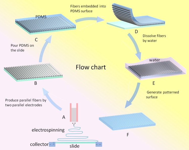
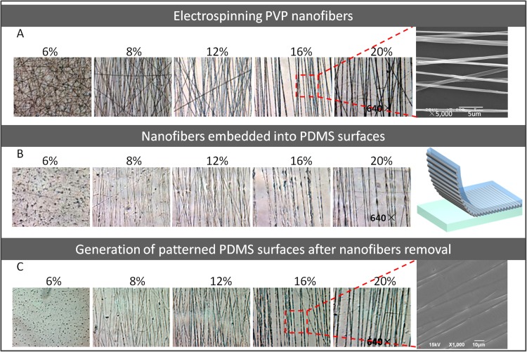
Electrospinning methods can create special arrangement fibers, such as disordered fibers, aligned fibers, fan-shaped radiating fibers, and crossed fibers.34, 35, 36 In this work, PVP is used for electrospinning fiber, which has good water-solubility and high molecular weight. The alignment PVP nanofibers were achieved using a modified collector with the electrospinning condition of 7.5 kV and 8 μl/min.34 In detail, two parallel alumina strips with a small gap (less than 2.5 cm) were employed as fibers collector instead of conventional flat silicon wafer. When driven by electrostatic field, the charged polymer solution was stretched to span across the gap and become perfectly aligned arrays over large areas (Fig. 1a). Then fiber arrays were transferred onto a clean glass slide (Fig. 1b). In this part, five concentrations of PVP solution (6%, 8%, 12%, 16%, and 20%) were tested and the electrospun fibers were harvested with different diameter and alignment (Fig. 2a).
Figure 1.
Diagram depicting the process for patterning PDMS surface via electrospun nanofibers.
Figure 2.
The photographs of the electrospun PVP nanofibers and produced patterned PDMS surfaces under different concentrations. (a) The microscope images of the PVP nanofibers spun with five concentrations (640×). SEM image of PVP nanofibers spun with 16% initial concentration. (b) The microscope images of PDMS surfaces embedded with PVP nanofibers (640×). (c) The microscope images of patterned PDMS surfaces after fibers removal (640×). SEM image of PDMS surfaces patterned with microstructures.
Generation of patterned biocompatible PDMS surfaces
In this work, the electrospun PVP nanofibers on the glass slide were chosen to serve as the template to produce the patterned PDMS surface via soft lithography. Before the patterning process, PDMS prepolymer and curing agent were mixed (10:1) and poured onto this template and then cured at 80 °C for 1 h (Fig. 1c). After solidifying, the PDMS was peeled off from the slide, in which the PVP fibers had been embedded into PDMS materials (Fig. 1d). Then, the whole slide were immerged into the water for 24–48 h (Fig. 1e), and thus, the patterned PDMS surface with concave fiber microstructures was produced due to the solubility of PVP. In conformity with the electrospinning fibers, five patterned surfaces were created with different diameter and alignment fibers. To evaluate the biocompatibility of pattern PDMS surface, OP9 stromal cells were cultured on the surface and the cell morphology and proliferation were characterized as follows. The cells were grown on the modified PDMS surface for up to 5 days and cells morphology was observed by fluorescence microscope. The cell proliferation had been investigated after 24 h cell culture and the proliferation rate was gained by calculating the cell numbers. The generated surfaces patterned by five electrospun PVP solution concentrations (6%, 8%, 12%, 16%, and 20%) were employed and an unpatterned surface was used as control.
Integrating nanofiber patterned surfaces with microfabricated microchannel for cell migration evaluation
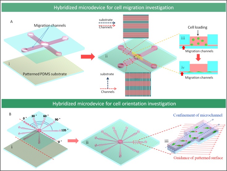
The fabricated microfluidic device was used to study the cells migration after integrating with 16% PVP nanofiber patterned PDMS surface. As shown in Fig. 3(a,i), the microfluidic device was composed of two layers. The upper layer had a cross channel array and there were seven paratactic channels (migration channels) in each cross branch of the array. The width of each channel was 80 μm and the interval between channels was 30 μm. Also the depth of the channels was 5 μm that was lower than the diameter of round cells (around 10 μm) but higher than the thickness when cell spread (2–3 μm). The lower layer was the patterned surface with parallel fibers generated from 16% PVP solution. The two layers were bonded using oxygen plasma. In this design, the relationships between the channels and patterned surface were classified into two cases according to the direction of fiber relative to microchannel, parallel and perpendicular (Fig. 3(a,ii)). There were five pools connected with the migration channels on the upper layer. The larger pool in the center was the inoculation pool for cells and medium injection and the other four smaller pools were designed to balance air pressure.
Figure 3.
The designed microdevice for cell behavior investigation by integrating microfluidic channel with PDMS substrate sacrificed by nanofibers. (a) The illustration of the microdevice for investigating cell migration on patterned surfaces. (b) The schematic of microdevice for investigating cell orientation under combined effects of microchannel spatial confinement and patterned surface guidance.
When cells were inoculated initially, unattached cells with round shape were blocked away from the channels due to the depth of the migration channels (Fig. 3(a,iii)) and cells could climb into the migration channels only after they attached on the surface (Fig. 3(a,iv)). So this microfluidic device could enable the cells to move into the migration channels by growing naturally and the cell movement velocity and cell number in the migration channels could denote the cell migratory ability in this direction. In this experiment, the cells in device were cultured in static situation and the media in all channels was changed every day to insure the supply of nutrition for cells.
Combining nanofiber patterned surfaces with microfluidic channel for cells orientation investigation
In order to study the cell orientation under the combinational factors of spatial confinement and sub-micro patterned surface guidance, the microfluidic channel was designed to enable the experiment. The designed hybridized PDMS microdevice consists of two layers, in which the upper layer had ten channel modules in radial distribution from central pool to peripheral region. These channels had different angle with symmetrical axes and each channel module contained five different width segments with 80 μm, 120 μm, 180 μm, 270 μm, and 405 μm, respectively. The lower layer was the patterned surface made from sacrificed parallel nanofibers from 16% PVP solution and the two layers were bonded by oxygen plasma (Fig. 3(b,ii)). There were eleven pools in the upper layer with one in the center and ten at the end of channels. The center one was the inoculation pool and the others were waste pools. Fig. 3b, showed that the channels were arranged with same angle distribution evenly. The angle 0° was defined as the top layer axial channels paralleling with the patterned surface on the lower layer, and the other channels was fabricated from the initial one to 30°, 60°, 90°, 135°(45°) sites. Accordingly, due to the symmetrical design, the other part of channels had the same angles with the patterned surface as this one.
RESULTS AND DISCUSSION
Generation of patterned PDMS surfaces via electrospun nanofibers
In this work, we first demonstrated the generation of nano or sub-micro scale patterned PDMS surface simply by using electrospun PVP nanofiber as a template. This approach for surface pattern at micro-/nano-scale has huge potential for biological and biophysical investigation. The surface with diverse nanopatterns can be easily achieved by adjusting related parameters such as fiber collector configuration, the distance from nozzle to collector, and relaxation time. In this experiment, a modified collector was used to harvest parallel fibers, in order to study the cells migration and orientations on alignment patterned surfaces. The structure dimension on pattern surface is directly correlated to the diameter of the electrospun fibers which is defined by initial polymer concentration. As shown in Fig. 2a, the alignment nanofibers were electrospun by using five kinds of PVP solutions with concentrations of 20%, 16%, 12%, 8%, and 6%, respectively. The results indicated the fibers exhibited more uniform morphology and dimension structure under the higher PVP concentration than that under low concentration solution. Also, the fiber diameter increases along with the initial polymer concentration. The higher concentration polymer solution generated relative large diameter and good mechanical strength fiber due to its higher viscosity. In this study, the 16% concentration PVP solution is an optimal condition to generate fibers array and the diameter of fibers was 650–850 nm. Fig. 2b showed that the fibers could be embedded into the PDMS surfaces completely and the patterned surfaces were the reflection replica of the fibers. After being immersed in water for 48 h, the hydrophilic PVP fibers could be eliminated from the incorporated PDMS completely, leading to the generation of concave microstructures on the PDMS surface (Fig. 2c). During the experiment, we found that the width of the microstructures was slightly bigger than the diameter of the sacrificed fibers, for example, the width of microstructures modified with 16% PVP fibers in PDMS surface were 1000–1200 nm comparing to original PVP fiber with a diameter of 650–850 nm, and the extended width of microstructures might be due to the influence of the PVP fiber dissolving process or the extension effect after fiber merging into PDMS under high temperature.
In this work, the proposed nanofiber supported micro/nano patterning method demonstrated several obvious advantages. First, it is very simple and fast, and the whole patterning process including nanofiber preparation is less in 2–3 h. Second, it is easily operated, without the requirement of complicated and expensive instrument, and it is also a potential technique for other fields to obtain patterned surfaces, especially for those laboratories without specialized equipment for surfaces patterning. Third, PDMS as the modified material retains all the advantages for cell related biological research such as good biocompatibility, air permeability, and light transmission, thus, providing an affordable method for a wide range of biological applications. Finally, the patterned PDMS layer is easy to integrate with other materials like glass, polystyrene, and PMMA and extended applications can be achieved with the flexible micro/nano structure surface patterning.
Viability and proliferation of cells on patterned surfaces
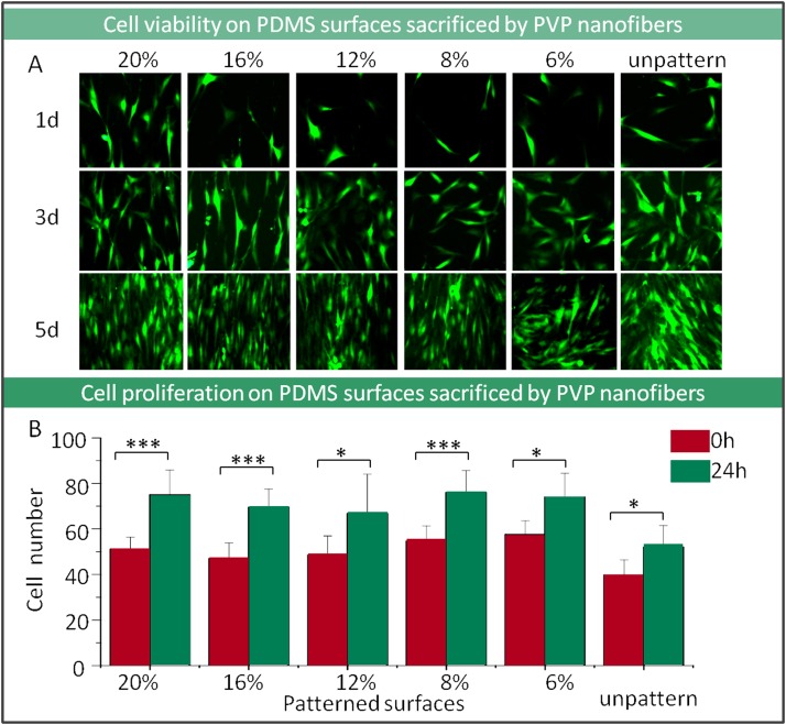
Cells compatibility with the PDMS surface sacrificed by PVP nanofibers is the fundamental index for biological related investigation. The OP9 stroma cells which had been labeled with green fluorescence protein were seeded on the PDMS patterned surfaces up to 5 days. According to the microscope observation, cells growth and morphology on pattern surface were in well condition, and the cells behaviors were obviously guided by grooves patterned in PDMS surface with spindle shape compared to those which grew on unpatterned surfaces (Fig. 4a). Patterned surfaces by higher PVP concentration fibers were easier to guide cell growth direction and morphology because of its uniform morphological surfaces. The cells proliferation rates which calculated based on cell number showed no significant difference between different dimensional nanofiber pattern surface groups and control unpatterned surface (Fig. 4b). That indicated that the PDMS surfaces patterned by PVP fibers sacrificed approach were nontoxic with good biocompatibility. The biocompatibility of the patterned surface mainly depends on the surface material components property. In this work, the sacrificed fiber components can be washed completely after immerging into specific solvent and water with sonic facilitation without affecting the cell physiological property.
Figure 4.
Characterization of cell viability and proliferation on PDMS surfaces by using PVP nanofibers sacrificed method. (a) The images of cell morphology on surfaces that patterned with different diameters of PVP nanofibers (100×). (b) Cell proliferation on patterned surfaces by counting cell number (***P < 0.001, *P < 0.05).
Guidance of cells migration on patterned surfaces in microsystem
Based on the investigation about cell viability and growth manner on fiber patterned PDMS surface, cell migration research in this in vivo microenvironment mimicry tool is significant and very important for inflammatory and tumor cell metastatic.
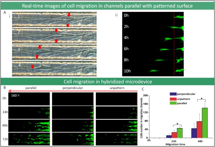
Herein, we demonstrated an integrated device which is composed of alignment patterned surfaces on bottom layer and microchannel confinement compartment on top layer, this design will evaluate cell migration on patterned surfaces more accuracy (Fig. 3a). As we know, when cells grow on the alignment patterned surfaces, the relationship between the patterned surfaces and the cells could be divided into two categories: parallel and perpendicular. To achieve this, patterned PDMS surface was incorporated into microfluidic device in our work. As shown in Fig. 3a, the microchannels were designed by cross distribution, if one direction of the channels was parallel with the patterned surface and then the other one was perpendicular. In order to quantify the migration of cells, approximately, the depth of migration channels was designed to be 5 μm, which was higher than adherent cells thickness (around 3–4 μm high) but lower than the cells diameter when it was inoculated shortly with round shape (around 10 μm high). The cells could creep towards the microchannel from the similar level around the inlet after cells attachment on the surface. Guided by surface alignment structure and microchannel confinement, it was observed that the cells crept into the microchannels from inlet pool after adherence. The cell moving velocity and cell number inside the microchannel reflected the cells migratory ability. Figs. 5a, 5b showed that cells migration distance increased over time and real time observation was available for single cell migration in detail. Comparison of the three images with different surfaces pattern under microchannels in Fig. 5b, cell migration in parallel microchannels with the patterned surface was fastest and cell migration of perpendicular channels was slowest. Accordingly, the Fig. 5c also demonstrated that the number of cells in parallel channels with patterned surface achieved to maximum due to microstructure guidance.
Figure 5.
Cell migration investigation used microdevice by integrating microfluidic channel with nanofiber patterned surface. (a) The real-time images of cell migration in the microchannels which are parallel with the patterned surface (100×). (b) The fluorescent microscope images of cell migration in the microchannels that are parallel or perpendicular with patterned surface (100×). (c) The comparison of migrated cells number in microfluidic channels (*P < 0.05).
Cell migration has been described as a multistep process with cell cytoskeletal protein polymerization and cell contraction,37 and the cell-substratum attachment strength is a central variable governing factor for cell migration speed.38 As shown in Fig. 5(a,i), cells in parallel channels with modified surface stretched along the microstructures, which could induce the leading edge of cell to move speedily. Furthermore, the micro-structures on the substrate reduced the contact area and strength between cells and surfaces, which also improved cell movement. On the other hand, in perpendicular channels with the modified surface, the extending of cells which govern by the surface microstructures were not in the same direction with migration, but the contact strength between cells and surfaces was decreased. In this condition, the cell stretch rate is similar to the control group. Taken all, this novel and well-defined device provide suitable platform for cell migration and the related mechanism investigation, especially for single cell migration.
Orientation of cells under combined effects of spatial factor and submicro-patterned surfaces
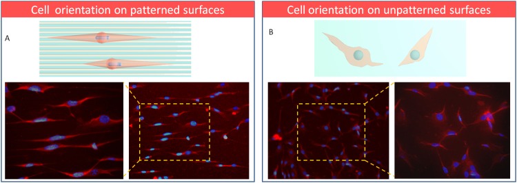
Above, cell migration was evaluated by an integrated microdevice which included migration microchannels and PDMS surface sacrificed by PVP nanofibers. The results indicated that cell migration was correlated with two effects of cytoskeletal protein polymerization in the cell leading edge and cell-substrate attachment strength. Here, a more sophisticated integrated device with multi-angle microchannels and alignment patterned surface was designed and fabricated for cell orientation study (Fig. 3b). With this integrated device, we would like to clarify which factor dominates the cell orientation, microchannels spatial confinement or patterned surface guidance? The complicated situation can be elaborated as below: first, when the direction of microchannel on top layer was the same as the microstructures on the bottom surface (0°), as shown in Fig. 6a, the cells orientation were uniform and even the nucleus was observed elongated with the cells extending on patterned surfaces. This result had been reported previously by other researchers and it could be explained by contact guidance.12, 13, 14, 15, 16, 17, 18, 19 Spontaneously, on the unpatterned ones, the cells orientation was disorder and the nucleus shape was round and no oriented tendency (Fig. 6b). Second, as variety of angles were generated by the cross of microchannels and alignment patterned surfaces, what is the crucial aspect for cell orientation under this microenvironment? It is an interesting problem but has not been studied before. This device provides the possibility to research this in multi-conditions at the same time.
Figure 6.
The immunofluorescent staining images of cell orientation on patterned (a) and unpatterned surfaces (b) (100×) (red: F-actin, blue: nuclei stained with DAPI).
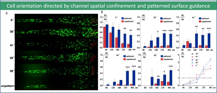
As shown in Figs. 7a, 7b, the orientation of cells was mainly decided by patterned surfaces in wider microchannels like 270 μm, 405 μm, but in narrower channels (80 μm, 120 μm), the orientation of cells was guided by microchannels confinement and direction. The results were double confirmed by the orientation rate which was defined as the ratio of cell number whose orientation was consistent with surface microstructures dividing by the total cells number in microchannel. The explanation could be that as the microchannel confinement factor was not obvious in the relatively wider channels, the contact guidance from patterned surface will be the decisive factor of cells orientation. In narrow microchannels, cell growth and proliferation were dominated by the confinement effect and so the contact guidance was not the leading factor. The results showed that the cell orientation was consistent with microchannel direction. Therefore, there was no significant difference on both patterned and unpatterned surfaces in narrower channels. It was a special case when the modified surface had the same direction with the channels (0°), because both two aspects induced the cells to grow into the same direction. In this way, the orientation rate was very high and it was proportionate with the declining of the channels width. As mentioned again, Fig. 7b chart illuminated the cell orientation behavior in confinement microchannel with patterned PDMS surface quantitatively. Overall, we found that the threshold value of microchannel dimension for governing cells orientation was between 120 and 270 μm. This study provided a thread for integrative biology investigation about cell migration especially for tumor metastatic mechanism and anti metastatic drug high throughput screening.
Figure 7.
Cell orientation under combined effects of microchannel spatial confinement and nanofiber patterned surface guidance. (a) The fluorescent images of cell orientation within diverse diameter microchannels with different angle on the microfiber patterned surface. (100×) (red solid lines represent patterned surface orientation). (b) The decisive factor of cells orientation in complicated microenvironments. (N1: the cell number which is counted having the same orientation with patterned surfaces in confined microchannel; N2: the total cell number in confined microchannel; N3: the cell number which is counted having the same orientation with the microchannel).
CONCLUSIONS
This work demonstrated a simple and novel approach to pattern PDMS surface with PVP electrospinning fibers sacrificed method. Integration of the pattern surface with microchannels confinement directs cell migration and orientation dramatically. It is a very suitable platform for compromising different factors effects on cell biological and physics-biological behavior study. This approach displayed obvious advantages including easy operation, fast, inexpensive, good biocompatibility, and easily integrated with other tool and has huge potential for cell biological related mechanism exploration in microscale and nanoscale systems.
ACKNOWLEDGMENTS
This research was supported by Key Project of Chinese National Programs for Fundamental Research and Development (973 program, Nos. 2007CB714505 and 2007CB714507), Knowledge Innovation Program of the Chinese Academy of Sciences (KJCX2-YW-H18), and Instrument Research and Development Program of the Chinese Academy of Sciences (YZ200908).
References
- Yang Y. and Leong K. W., WIREs Nanomed. Nanobiotechnol. 2, 478 (2010). 10.1002/wnan.74 [DOI] [PubMed] [Google Scholar]
- Kim D. H., Lee H., Lee Y. K., Nam J. M., and Levchenko A., Adv. Mater. 22, 4551 (2010). 10.1002/adma.201000468 [DOI] [PubMed] [Google Scholar]
- Lo C. M., Wang H. B., Dembo M., and Wang Y. l., Biophys. J. 79, 144 (2000). 10.1016/S0006-3495(00)76279-5 [DOI] [PMC free article] [PubMed] [Google Scholar]
- Revzin A., Rajagopalan P., Tilles A. W., Berthiaume F., Yarmush M. L., and Toner M., Langmuir. 20, 2999 (2004). 10.1021/la035827w [DOI] [PubMed] [Google Scholar]
- Li H. Y., Friend J., Yeo L., Dasvarma A., and Traianedes K., Biomicrofluidics. 3, 34102 (2009). 10.1063/1.3194282 [DOI] [PMC free article] [PubMed] [Google Scholar]
- Teixeira A. I., Abrams G. A., Bertics P. J., Murphy C. J., and Nealey P. F., J. Cell Sci. 116, 1881 (2003). 10.1242/jcs.00383 [DOI] [PMC free article] [PubMed] [Google Scholar]
- Flemming R. G., Murphy C. J., Abrams G. A., Goodman S. L., and Nealey P. F., Biomaterials. 20, 573 (1999). 10.1016/S0142-9612(98)00209-9 [DOI] [PubMed] [Google Scholar]
- Mossman K. D., Campi G., Groves J. T., and Dustin M. L., Science. 310, 1191 (2005). 10.1126/science.1119238 [DOI] [PubMed] [Google Scholar]
- Balaban N. Q., Schwarz U. S., Riveline D., Goichberg P., Tzur G., Sabanay I., Mahalu D., Safran S., Bershadsky A., Addadi L., and Geiger B., Nat. Cell Biol. 3, 466 (2001). 10.1038/35074532 [DOI] [PubMed] [Google Scholar]
- Dalby M. J., Gadegaard N., Tare R., Andar A., Riehle M. O., Herzyk P., Wilkinson C. D. W., and Oreffo R. O. C., Nat. Mater. 6, 997 (2007). 10.1038/nmat2013 [DOI] [PubMed] [Google Scholar]
- Bakeine G. J., Benedetti L., Galli D., Grenci G., Pozzato A., Prasciolu M., Tormen M., and Cusella G., Microelectron. Eng. 87, 830 (2010). 10.1016/j.mee.2009.10.024 [DOI] [Google Scholar]
- Teixeira A. I., McKie G. A., Foley J. D., Bertics P. J., Nealey P. F., and Murphy C. J., Biomaterials. 27, 3945 (2006). 10.1016/j.biomaterials.2006.01.044 [DOI] [PMC free article] [PubMed] [Google Scholar]
- Yim E. F., Pang S. W., and Leong K. W., Exp. Cell Res. 313, 1820 (2007). 10.1016/j.yexcr.2007.02.031 [DOI] [PMC free article] [PubMed] [Google Scholar]
- Kim D. H., Lipke E. A., Kim P., Cheong R., Thompson S., Delannoy M., Suh K. Y., Tung L., and Levchenko A., Proc. Natl. Acad. Sci. 107, 565 (2010). 10.1073/pnas.0906504107 [DOI] [PMC free article] [PubMed] [Google Scholar]
- Xie J. W., Ewan M. R. M., Schwartz A. G., and Xia Y. N., Nanoscale. 2, 35 (2010). 10.1039/b9nr00243j [DOI] [PubMed] [Google Scholar]
- Gil E. S., Park S. H., Marchant J., Omenetto F., and Kaplan D. L., Macromol. Biosci. 10, 664 (2010). 10.1002/mabi.200900452 [DOI] [PMC free article] [PubMed] [Google Scholar]
- Jeon H., Hidai H., Hwang D. J., Healy K. E., and Grigoropoulos C. P., Biomaterials. 31, 4286 (2010). 10.1016/j.biomaterials.2010.01.103 [DOI] [PubMed] [Google Scholar]
- Hwang S. Y., Kwon K. W., Jang K. J., Park M. C., Lee J. S., and Suh K. Y., Anal. Chem. 82, 3016 (2010). 10.1021/ac100107z [DOI] [PubMed] [Google Scholar]
- Baker B. M., Nathan A. S., Gee A. O., and Mauck R. L., Biomaterials. 31, 6190 (2010). 10.1016/j.biomaterials.2010.04.036 [DOI] [PMC free article] [PubMed] [Google Scholar]
- Khan S. and Newaz G., J. Biomed. Mater. 93A, 1209 (2010). 10.1002/jbm.a.32698 [DOI] [PubMed] [Google Scholar]
- Torres A. J., Wu M., Holowka D., and Baird B., Annu. Rev. Biophys. Biomol. Struct. 37, 256 (2008). 10.1146/annurev.biophys.36.040306.132651 [DOI] [Google Scholar]
- Wu B. and Kumar A., J. Vac. Sci. Technol. B 25, 1743 (2007). [Google Scholar]
- Vieu C., Carcenac F., Pepin A., Chen Y., Mejias M., Lebib A., Manin-Ferlazzo L., Couraud L., and Launois H., Appl. Surf. Sci. 164, 111 (2000). 10.1016/S0169-4332(00)00352-4 [DOI] [Google Scholar]
- Rundqvist J., Mendoza B., Werbin J. L., Heinz W. F., Lemmon C., Romer L. H., Haviland D. B., and Hoh J. H., J. Am. Chem. Soc. 129, 59 (2007). 10.1021/ja063698a [DOI] [PubMed] [Google Scholar]
- Zheng Y. Z., Dai W., Ryan D., and Wu H. K., Biomicrofluidics 4, 36504 (2010). 10.1063/1.3491474 [DOI] [PMC free article] [PubMed] [Google Scholar]
- Piner R. D., Zhu J., Xu F., Hong S., and Mirkin C. A., Science 283, 66 (1999). 10.1126/science.283.5402.661 [DOI] [PubMed] [Google Scholar]
- Ginger D. S., Zhang H., and Mirkin C. A., Angew. Chem. Int. Ed., 43 –30., 30 (2004). 10.1002/anie.200390636 [DOI] [PubMed] [Google Scholar]
- Salaita K., Wang Y., and Mirkin C. A., Nat. Nanotechnol. 2, 145 (2007). 10.1038/nnano.2007.39 [DOI] [PubMed] [Google Scholar]
- Salaita K., Wang Y., Fragala J., Vega R. A., Liu C., and Mirkin C. A., Angew. Chem. Int. Ed. 45, 7220 (2006). 10.1002/anie.v45:43 [DOI] [PubMed] [Google Scholar]
- Reneker D. H. and Chun I., Nanotechnology 7, 216 (1996). 10.1088/0957-4484/7/3/009 [DOI] [Google Scholar]
- Burger C., Hsiao B. S., and Chu B., Annu. Rev. Mater. Res. 36, 333 (2006). [Google Scholar]
- Srivastava Y., Marquez M., and Thorsen T., Biomicrofluidics 3, 12801 (2009). 10.1063/1.3009288 [DOI] [PMC free article] [PubMed] [Google Scholar]
- Gao Ji., Yan X. L., Li R., Liu Y., He W. Y., Sun S. K., Zhang Y., Liu B., Xiong J. X., and Mao N., J. Genet. Genomics 37, 475 (2010). 10.1016/S1673-8527(09)60067-9 [DOI] [PubMed] [Google Scholar]
- Wu H., Zhang R., Sun a Y., Lin D. D., Sun Z. Q., Pan W., and Downs P., Soft Matter 4, 2429 (2008). 10.1039/b805570j [DOI] [Google Scholar]
- Li D., Ouyang G., McCann J. T., and Xia Y. N., Nano. Lett. 5, 913 (2005). 10.1021/nl0504235 [DOI] [PubMed] [Google Scholar]
- Zhang D. M. and Chang J., Adv. Mater. 19, 3664 (2007). 10.1002/adma.v19:21 [DOI] [Google Scholar]
- Sheetz M. P., Felsenfeld D. P., and Galbraith C. G., Trends Cell. Biol. 8, 51 (1998). 10.1016/S0962-8924(98)80005-6 [DOI] [PubMed] [Google Scholar]
- Dimilla P. A., Stone J. A., Quinn J. A., Albelda S. M., and Lauffenburger D. A., J. Cell. Biol. 122, 729 (1993). 10.1083/jcb.122.3.729 [DOI] [PMC free article] [PubMed] [Google Scholar]


