Abstract
Protein nanopores may provide a cheap and fast technology to sequence individual DNA molecules. However, the electrophoretic translocation of ssDNA molecules through protein nanopores has been too rapid for base identification. Here, we show that the translocation of DNA molecules through the α-hemolysin protein nanopore can be slowed controllably by introducing positive charges into the lumen of the pore by site directed mutagenesis. Although the residual ionic current during DNA translocation is insufficient for direct base identification, we propose that the engineered pores might be used to slow down DNA in hybrid systems, e.g. in combination with solid-state nanopores.
Keywords: alpha-hemolysin, DNA sequencing, nanopore, protein engineering, DNA translocation
The ability to sequence the human genome rapidly (e.g. in 15 minutes) and at an affordable price (e.g. US $1000) would be a turning point in medicine. At that price and speed, most people could afford to have their genome sequenced on-the-fly for tailored medical treatment. Thanks to advances in second-generation DNA sequencing techniques, the cost of sequencing an entire human genome is now about US$ 50,000.1, 2 However, most second-generation technologies such as those implemented by 454 Life Sciences (Roche), Solexa (Illumina) and Applied Biosystems SOLiD™ (Life Technologies), rely on slow iterative cycles of enzymatic processing and imaging-based data collection. Therefore, the most likely candidates to cross the US $1000 and 15-minute human genome barrier will be third-generation single-molecule sequencing platforms, such as Pacific Bioscience’s single molecule-real time sequencing by synthesis (SMRT™) or nanopore sequencing,3 which are based on the continuous determination of sequences of individual DNA molecules by cycle-free processes.
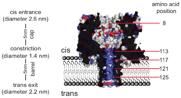
In one approach to nanopore sequencing, a single-stranded DNA or RNA molecule is driven electrophoretically through a nanopore and each DNA base is read as it passes a recognition point.3 In its simplest manifestation, the current associated with the passage of ions (e.g. K+ and Cl−) through the nanopore during DNA translocation provides the electrical read-out required to distinguish each base. In our laboratory, we use α-hemolysin (αHL) protein nanopores reconstituted in planar lipid bilayers (Figure 1). Notably, we have shown that the four DNA bases,4–6 including their epigenetically modified forms, 5-methylcytosine and 5-hydroxymethylcytosine,7 can be discriminated in a DNA strand immobilized within the nanopore.
Figure 1.
Section through a 7R7 nanopore. The amino acids at positions 113, 115, 117, 119, 121, 123 and 125 were replaced in the WT7 nanopore (PDB:7AHL) by arginine by using PyMOL software (DeLano Scientific LLC, v1.0). 7R7 is in the RL2 background, in which lysine 8 is replaced by alanine as shown here. Negatively charged residues are colored in red and positively charged residues in blue.
Alternatively, single nucleotides are identified by reading the tunnelling current passing through individual DNA bases, while a DNA strand is translocating through a solid-state nanopore modified with tunnelling probes.8–10 Tunnelling readings would be advantageous because the nano-ampere range of tunnelling currents will allow the reading of nucleotides at a greater speed than with the pico-ampere ionic currents through protein nanopores.3 In addition, since the tip of the probe can be less than 1 nm in diameter,3 a single nucleotide would be addressed by the tunnelling probe at any given time.
One of the main remaining challenges in nanopore sequencing is to reduce the speed of DNA translocation through the nanopore, which is too fast to allow discrimination between individual nucleobases by using either ionic11 or tunnelling3 currents. Previous attempts to reduce the speed of free DNA translocation have included the use of low temperatures12 and increased viscosity13, 14. These approaches reduced the speed of DNA translocation by one order of magnitude or less, at the expense of a large decrease in the ionic current. In this work, we show that by lining the transmembrane region of the αHL pore with positively charged residues, the speed of DNA translocation can be slowed by more than two orders of magnitude. Although, the ionic current during DNA translocation is again almost completely suppressed, we suggest that such nanopores could be used to control the speed of DNA translocation in hybrid protein and solid-state nanopores.
Ionic currents through αHL nanopores
The heptameric αHL nanopore contains a cap domain and a barrel domain, which are separated by an inner constriction that is 1.4 nm in diameter (Figure 1).15 We made a variety of homo- and hetero-heptameric αHL pores in which the charge distribution within the barrel was altered. In homo-heptamers the mutations appear in all seven subunits, while in hetero-heptamers the charge is changed in a subset of the subunits. All mutants were made by using the RL2 genes as templates, except for the NN7 pore, in which the WT gene was used (SI). WT pores contain an additional positive charge at position 8 in the form of a lysine residue (Figure 1).
The unitary conductance values (g) in 1 M KCl solutions (containing 25 mM Tris.HCl and 100 μM EDTA at pH 8.0) varied greatly among the nanopores (Table 1). The introduction of positive charges close to the constriction increased the conductance of the nanopores at positive applied potentials with respect to the WT7 and RL27 pores. By contrast, when positive charges were introduced close to the trans exit of the pore, the ionic current at positive potentials was reduced significantly16 (Table 1). The rectification ratios (g+/g−), calculated from the value of the ionic current at +50 mV divided by the current at −50mV, also varied depending on the position of the introduced charges. Nanopores with additional positive charges near the trans exit (after position 121) showed g+/g− < 1, while mutants with positive charges close to the constriction displayed rectifying behaviour similar to that of WT7 (g+/g− >1). On the other hand, NN7 pores, which have no charged groups at the central constriction, displayed g+/g− ~ 1. In agreement with previous findings,17–19 these results suggest that the transport of ions through the relatively narrow αHL nanopore can be strongly influenced by the introduction of charged residues within the β barrel.
Table 1.
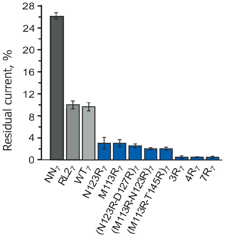
DNA translocation through αHL nanopores at +120 mV in 1 M KCl, 25 mM Tris.HCl containing 100 μM EDTA at pH 8.0. tb is the most likely DNA translocation time per base; f is the normalized frequency of DNA translocation; g is the unitary conductance and IRES is the residual current during DNA translocation. For IRES, the errors were all less than ±1%. All mutants, except NN7, are in the RL2 background (WT pores contain an additional positive charge at position 8 in the form of a lysine residue, SI). Errors are shown as standard deviations.
| Pore | tb (μs/base) | f (s−1μM−1) | IRES (%) | g, nS (+120mV) |
|---|---|---|---|---|
| WT7 | 1.5±0.1 (n=6) | 3.0±0.2 (n=12) | 10 (n=5) | 1.01±0.01 (n=23) |
| NN7 (E111N-K147N) | 2.0±0.1 (n=4) | 0.79±0.12 (n=4) | 26 (n=4) | 1.07±0.05 (n=4) |
| RL27 | 1.6±0.1 (n=4) | 0.28±0.04 (n= 5) | 10 (n=4) | 1.03±0.02 (n=16) |
| M113R7 | 1.5±0.1 (n=4) | 4.4± 0.6 (n=7) | 3 (n=5) | 1.17±0.02 (n=8) |
| N123R7 | 2.4±0.5 (n=5) | 0.43±0.04 (n= 8) | 3 (n=4) | 0.64±0.02 (n=10) |
| (M113R-N123)7 | 3.0±0.3 (n=8) | 6.2±1.9 (n=7) | 2 (n=4) | 0.97±0.05 (n=6) |
| (N123R-D127R)7 | 4.4±0.2 (n=5) | 0.4±0.05 (n=4) | 2 (n=5) | 0.57±0.03 (n=4) |
| (M113R-T145R)7 | 4.5±0.7 (n=5) | 5.2±1.0 (n=5) | 2 (n=5) | 1.06±0.06 (n=5) |
| 3R7 (T115R, G119R, N123R)7 | 16±4 (n=7) | 4.2±1.4 (n=5) | <1 (n=6) | 0.87±0.06 (n=7) |
| 4R7 (T115R, G119R, N123R, D127R)7 | 29±6 (n=4) | 3.5±3.5 (n=4) | <1 (n=4) | 0.70±0.09 (n=6) |
| 7R7 (M113R-T115R-T117R- G119R-N121R-N123R- T125R)7 | 270±10 (n=6) | 5.4±1.6 (n=6) | <1 (n=6) | 0.91±0.04 (n=10) |
| 7R6 RL21 | 120±10 (n=7) | 1.54±0.5 (n=6) | <1 (n=5) | 0.95±0.06 (n=7) |
| 7R5 RL22 | 67±10 (n=5) | 3.5±0.8 (n=4) | <1 (n=5) | 0.88±0.09 (n=5) |
| 7R4 RL23 | 51±6 (n=5) | 3.3±0.7 (n=5) | <1 (n=5) | 0.87±0.05 (n=5) |
| 7R3 RL24 | 21±9 (n=7) | 4.0±1.5 (n=7) | 1 (n=5) | 0.94±0.05 (n=7) |
| 7R2 RL25 | 9.9±2.2 (n=5) | 2.3±0.5 (n=4) | 2 (n=5) | 0.93±0.07 (n=5) |
| 7R1 RL26 | 6.0±1.1 (n=5) | 1.7±0.3 (n=5) | 4 (n=4) | 0.99±0.05 (n=5) |
DNA translocation through homo-heptameric αHL nanopores
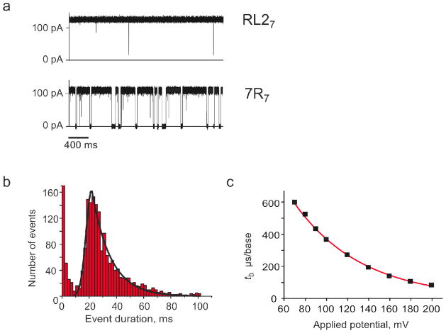
The addition of a 92mer ssDNA designed to contain no secondary structure (5′-AAAAAAAAAAAAAAAAAAAAATTCCCCCCCCCCCCCCCCCCCCCTTAAAAAAAAAATTCCCCCCCCCCTTAAAAAAAAAATTCCCCCCCCCC-3) to WT7 and RL27 pores from the cis chamber under positive applied potentials provoked current blockades that are due to the translocation of individual DNA molecules through the pore20 (Figure 2a). At +120 mV, the most likely translocation time, tP, which is defined as the peak of a Gaussian fit to a histogram of translocation times,12 was 0.14±0.01 ms for both WT7 and RL27 nanopores,16 corresponding to the mean most likely translocation time per base (tb = tp / number of nucleotides) of 1.5 μs/nt.
Figure 2.
DNA translocation through 7R7 nanopores. a) Single-channel recordings of RL27 (top) and 7R7 nanopores (bottom) at +120 mV after the addition of 1.0 μM 92-mer ssDNA to the cis compartment. b) Event histogram showing the translocation time distribution at +120 mV through a 7R7 pore upon addition of 0.7 μM ssDNA (92-mer) to the cis compartment. Events of < 10 ms are attributed to the transient gating of the 7R7 nanopore and are ignored (Figure S1). The solid line shows a fit to the histogram of a Gaussian followed by a single exponential.12 The most likely translocation time (tP) is defined by the peak of the Gaussian fit.12 c) Dependence on the applied voltage of the most likely translocation time per base (tb = tP / 92) of ssDNA (92 mer) through 7R7 nanopores. The red line shows a single exponential fit. Experiments were performed in 1 M KCl, 25 mM Tris.HCl, containing 100 μM EDTA, at pH 8.0.
The manipulation of charges in the barrel of the pore altered the interaction between the DNA and the pore. The addition of one ring of arginine residues near the constriction of RL2 pores (M113R7) increased the frequency of DNA translocation by 16-fold.16 Interestingly, nanopores containing two or more rings of positive charge in the barrel showed only a small additional increase in the frequency of DNA translocation (30% for (M113R-N123)7, which was the pore that showed the highest increase, Table 1); indicating that one ring of arginine residues in the barrel is sufficient to enhance the frequency of DNA translocation to near its maximum value.16
The removal of the charges at the central constriction in NN7 or the introduction of one or two rings of arginine residues within the lumen of homo-heptameric RL2 pores (7 or 14 additional positive charges) had only a small effect on the most likely translocation time (tP) for the 92mer or other short ssDNA or RNA molecules.19, 21 For all double arginine mutants tested (Table 1),tP was just 2-or 3- fold higher than the value observed with WT7 and RL27 pores (Table 1). However, the introduction of three (3R7) or four (4R7) rings of arginine residues within the barrel increased the most likely translocation time by ~10- and ~20-fold, respectively; while seven rings of arginines residues (7R7), increased the translocation time by more than two orders of magnitude relative to the WT7 and RL27 values (Table 1). In all the nanopores studied, the translocation times of the current blockades induced by DNA showed a Gaussian distribution followed by an exponential tail (Figure 2b). The most likely translocation time per base decreased exponentially with the applied potential (Figure 2c), confirming that, as for WT7 pores, individual DNA molecules are translocated through the pore rather than binding and dissociating from the cis side.22–25
Residual currents through homo-heptameric αHL nanopores
When a DNA molecule is translocating through a nanopore, the ionic current is reduced from the open pore current (IO) to the blocked pore current (IB). In WT7 and RL27 nanopores the residual current (IRES), defined as IB divided by IO expressed in percent, is ~10%16, 20, 26 (Table 1). Modification of the charge distribution within the barrel of the pore has a powerful effect on IRES. For example, the NN7 pore, in which the charged residues of the central constriction are substituted by smaller, neutral residues, shows an increased residual current, IRES=26% (Table 1), while the introduction of large, positively charged arginine residues greatly reduces IRES (Table 1). One ring of arginine reduces IRES to 3%, while three or more sets of arginine residues almost completely suppress the residual current (IRES < 1%).
The effect of arginine substitutions on the residual current during DNA translocation is most likely due to the reduced cross-section of the lumen of the pore, given the increased bulk of the arginine side chains by comparison with the side-chains in WT7 nanopores,5 which limit the current flow of hydrated ions through the pore. An additional reduction of the ionic flow is most likely due to the increased electrostatic self-energy of the translocating positive ions (e.g. K+)27, 28 that follows the introduction of the positive charges in the lumen of the pore. Finally, it is also possible that the interaction of the positive charges of the arginine side chains with the backbone phosphates of DNA29 triggers a partial collapse of the β barrel around the DNA, which in turn prevents the passage of ions through the pore.
DNA translocation through αHL hetero-heptameric pores
Hetero-heptameric αHL pores were prepared by mixing 7R-monomers containing an eight-aspartate tail (D8) at the C terminus with RL2-monomers, followed by separation by SDS-PAGE (SI). When incorporated into heptamers, each 7R monomers provides seven arginine residues within the barrel (starting from the constriction and ending at the trans exit of the pore). It was hoped that the arginine side chains would interact with the phosphodiester linkages of DNA and reduce the rate of translocation, while the relatively small side-chains of the RL2-subunits would still allow the passage of a significant ionic current.
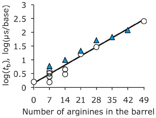
We found that hetero-heptameric pores containing 7R monomers were as efficient as homo-polymeric pores containing arginine residues at reducing the rate of translocation of DNA through the pore (Figure 4 and Table 1), with the translocation times per base showing an exponential dependence on the number of arginine residues in the barrel (Figure 4). Unfortunately, IRES was again reduced to almost zero when 21 or more arginine residues were introduced into the barrel of the pore (table 1).
Figure 4.
Dependence of the mean most likely translocation time per base (tb) at +120 mV on the number of arginine residues in the barrel of RL2 pores. Homo- and hetero-heptamers are shown in open circles and blue triangles, respectively. tb is expressed on a logarithmic scale and the data are fitted to a linear regression. Hetero-heptamers were obtained by mixing RL2- and 7R- monomers. Experiments were performed in 1 M KCl, 25 mM Tris.HCl, containing 100 μM EDTA, at pH 8.
Conclusions
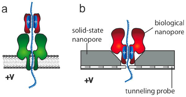
In this work, we have shown that molecular brakes in the form of additional positive charge can be engineered within the barrel of a protein nanopore to control the average speed of translocation of a short ssDNA molecule containing no secondary structure. Although the introduction of more than two positively charged residues per subunit in homo-heptamers or more than two 7R subunits in hetero-heptamers largely prevented the passage of ions through the pore, the results obtained here may still be useful for the implementation of nanopore sequencing platforms. For example, an artificial barrel containing positive charges could be paired with a pore capable of base recognition (e.g. NN7).4 The charge within the artificial barrel would be used to control DNA translocation, while the trans-membrane pore would recognize single DNA bases (Figure 5a). In such a construct, we believe that substantial current will flow, as previous studies have shown that proteins handling DNA placed at the cis entrance to the αHL nanopore do not drastically alter the ionic current through the pore and allow bases to be discriminated4, 30–32
Figure 5.
Potential uses of 7R7 nanopores. a) A protein nanopore (e.g. NN7, green) is used to detect base-specific ionic current differences in a DNA strand, while a synthetic protein barrel (red) containing positive charges is employed to control the speed of DNA translocation. b) A protein nanopore with positive internal charge (e.g. 7R7, red) is paired with a solid-state nanopore (gray) equipped with a tunnelling probe integrated into the device with atomic precision. The speed at which DNA is translocated through the solid-state nanopore is controlled by the applied potential and the number of positive charges in the barrel of the protein nanopore. Each base will be read by monitoring the tunnelling current, providing that the bases translocate at a constant speed and arrive with the same orientation at the tunnelling probe.
Alternatively, modified αHL pores could be inserted into solid-state nanopores33 paired with suitable tunnelling probes34–37 (Figure 5b). The feasibility of this approach has been described theoretically38–42 and the ability of scanning tunnelling microscopy to recognize single bases has been shown experimentally.43–45 However, in order to be identified during translocation through a nanopore, each DNA base would have to be addressed by the tunnelling probes for at least 100 μs,3 which is three orders of magnitude longer that the typical average translocation times of individual DNA bases or base pairs through solid state nanopores.3, 46–48 In addition, a reproducible orientation and positioning of the base at the tunneling probe will also be crucial, as electron-tunneling currents are exponentially sensitive to atomic scale changes of orientation and distance.3 Therefore, if tunnelling probes will be incorporated into solid-state nanopores with atomic precision, the hybrid protein and solid-state nanopore systems shown in figure 5b will be capable of informative data acquisition (tb = 270 μs/base at +120mV), providing that the speed of DNA translocation through the pore is constant and the orientation of each base at the tunnelling probe reproducible.3
Figure 3.
Residual current (IRES) through αHL nanopores during ssDNA translocation at +120 mV. Errors are expressed as standard deviations. All nanopores, except WT7 and NN7, are in the RL2 background. Nanopores with additional positive charge compared to the WT7 and RL27 pores are in blue. Experiments were performed in 1 M KCl, 25 mM Tris.HCl, containing 100 μM EDTA, at pH 8.0.
Acknowledgments
We are grateful to David Stoddart and to Gabriel Villar for proof reading and insightful comments and for helping with data fitting. This work was funded by the National Institutes of Health.
References
- 1.Drmanac R, Sparks AB, Callow MJ, Halpern AL, Burns NL, Kermani BG, Carnevali P, Nazarenko I, Nilsen GB, Yeung G, Dahl F, Fernandez A, Staker B, Pant KP, Baccash J, Borcherding AP, Brownley A, Cedeno R, Chen L, Chernikoff D, Cheung A, Chirita R, Curson B, Ebert JC, Hacker CR, Hartlage R, Hauser B, Huang S, Jiang Y, Karpinchyk V, Koenig M, Kong C, Landers T, Le C, Liu J, McBride CE, Morenzoni M, Morey RE, Mutch K, Perazich H, Perry K, Peters BA, Peterson J, Pethiyagoda CL, Pothuraju K, Richter C, Rosenbaum AM, Roy S, Shafto J, Sharanhovich U, Shannon KW, Sheppy CG, Sun M, Thakuria JV, Tran A, Vu D, Zaranek AW, Wu X, Drmanac S, Oliphant AR, Banyai WC, Martin B, Ballinger DG, Church GM, Reid CA. Science. 2010;327(5961):78–81. doi: 10.1126/science.1181498. [DOI] [PubMed] [Google Scholar]
- 2.Bonetta L. Cell. 2010;141(6):917–9. doi: 10.1016/j.cell.2010.05.034. [DOI] [PubMed] [Google Scholar]
- 3.Branton D, Deamer DW, Marziali A, Bayley H, Benner SA, Butler T, Di Ventra M, Garaj S, Hibbs A, Huang X, Jovanovich SB, Krstic PS, Lindsay S, Ling XS, Mastrangelo CH, Meller A, Oliver JS, Pershin YV, Ramsey JM, Riehn R, Soni GV, Tabard-Cossa V, Wanunu M, Wiggin M, Schloss JA. Nature Biotechnology. 2008;26:1146–1153. doi: 10.1038/nbt.1495. [DOI] [PMC free article] [PubMed] [Google Scholar]
- 4.Stoddart D, Heron A, Mikhailova E, Maglia G, Bayley H. Proc Natl Acad Sci USA. 2009;106:7702–7707. doi: 10.1073/pnas.0901054106. [DOI] [PMC free article] [PubMed] [Google Scholar]
- 5.Stoddart D, Heron AJ, Klingelhoefer J, Mikhailova E, Maglia G, Bayley H. Nano Lett. 2010;10(9):3633–7. doi: 10.1021/nl101955a. [DOI] [PMC free article] [PubMed] [Google Scholar]
- 6.Stoddart D, Maglia G, Mikhailova E, Heron AJ, Bayley H. Angewandte Chemie-International Edition. 2010;49(3):556–559. doi: 10.1002/anie.200905483. [DOI] [PMC free article] [PubMed] [Google Scholar]
- 7.Wallace EV, Stoddart D, Heron AJ, Mikhailova E, Maglia G, Donohoe TJ, Bayley H. Chem Commun (Camb) 46(43):8195–7. doi: 10.1039/c0cc02864a. [DOI] [PMC free article] [PubMed] [Google Scholar]
- 8.Zwolak M, Di Ventra M. Nano Letters. 2005;5(3):421–424. doi: 10.1021/nl048289w. [DOI] [PubMed] [Google Scholar]
- 9.Zikic R, Krstic PS, Zhang XG, Fuentes-Cabrera M, Wells J, Zhao XC. Physical Review E. 2006;74(1) doi: 10.1103/PhysRevE.74.011919. [DOI] [PubMed] [Google Scholar]
- 10.Lagerqvist J, Zwolak M, Di Ventra M. Nano Letters. 2006;6(4):779–782. doi: 10.1021/nl0601076. [DOI] [PMC free article] [PubMed] [Google Scholar]
- 11.Deamer D. Annu Rev Biophys. 2010;39:79–90. doi: 10.1146/annurev.biophys.093008.131250. [DOI] [PubMed] [Google Scholar]
- 12.Meller A, Nivon L, Brandin E, Golovchenko J, Branton D. Proc Natl Acad Sci U S A. 2000;97(3):1079–84. doi: 10.1073/pnas.97.3.1079. [DOI] [PMC free article] [PubMed] [Google Scholar]
- 13.Kawano R, Schibel AE, Cauley C, White HS. Langmuir. 2009;25(2):1233–7. doi: 10.1021/la803556p. [DOI] [PubMed] [Google Scholar]
- 14.Fologea D, Uplinger J, Thomas B, McNabb DS, Li J. Nano Lett. 2005;5(9):1734–7. doi: 10.1021/nl051063o. [DOI] [PMC free article] [PubMed] [Google Scholar]
- 15.Song L, Hobaugh MR, Shustak C, Cheley S, Bayley H, Gouaux JE. Science. 1996;274(5294):1859–66. doi: 10.1126/science.274.5294.1859. [DOI] [PubMed] [Google Scholar]
- 16.Maglia G, Rincon Restrepo M, Mikhailova E, Bayley H. Proc Natl Acad Sci U S A. 2008;105:19720–19725. doi: 10.1073/pnas.0808296105. [DOI] [PMC free article] [PubMed] [Google Scholar]
- 17.Gu LQ, Cheley S, Bayley H. Proc Natl Acad Sci U S A. 2003;100(26):15498–503. doi: 10.1073/pnas.2531778100. [DOI] [PMC free article] [PubMed] [Google Scholar]
- 18.Maglia G, Heron AJ, Hwang WL, Holden MA, Mikhailova E, Li Q, Cheley S, Bayley H. Nat Nanotechnol. 2009;4(7):437–40. doi: 10.1038/nnano.2009.121. [DOI] [PubMed] [Google Scholar]
- 19.Maglia M, Henricus M, Wyss R, Li Q, Cheley S, Bayley H. Nano Letters. 2009;9:3831–3836. doi: 10.1021/nl9020232. [DOI] [PubMed] [Google Scholar]
- 20.Kasianowicz JJ, Brandin E, Branton D, Deamer DW. Proc Natl Acad Sci U S A. 1996;93(24):13770–3. doi: 10.1073/pnas.93.24.13770. [DOI] [PMC free article] [PubMed] [Google Scholar]
- 21.Japrung D, Henricus M, Li QH, Maglia G, Bayley H. Biophysical Journal. 2010;98(9):1856–1863. doi: 10.1016/j.bpj.2009.12.4333. [DOI] [PMC free article] [PubMed] [Google Scholar]
- 22.Clarke J, Wu H, Jayasinghe L, Patel A, Reid S, Bayley H. Nature Nanotechnology. 2009;4:265–270. doi: 10.1038/nnano.2009.12. [DOI] [PubMed] [Google Scholar]
- 23.Braha O, Webb J, Gu LQ, Kim K, Bayley H. Chemphyschem. 2005;6(5):889–92. doi: 10.1002/cphc.200400595. [DOI] [PubMed] [Google Scholar]
- 24.Gu LQ, Cheley S, Bayley H. Science. 2001;291(5504):636–40. doi: 10.1126/science.291.5504.636. [DOI] [PubMed] [Google Scholar]
- 25.Sanchez-Quesada J, Ghadiri MR, Bayley H, Braha O. Journal of the American Chemical Society. 2000;122(48):11757–11766. [Google Scholar]
- 26.Meller A. J Phys: Condens Matter. 2003;15:R581–R607. [Google Scholar]
- 27.Bonthuis DJ, Zhang J, Hornblower B, Mathe J, Shklovskii BI, Meller A. Phys Rev Lett. 2006;97(12):128104. doi: 10.1103/PhysRevLett.97.128104. [DOI] [PubMed] [Google Scholar]
- 28.Zhang J, Shklovskii BI. Phys Rev E Stat Nonlin Soft Matter Phys. 2007;75(2 Pt 1):021906. doi: 10.1103/PhysRevE.75.021906. [DOI] [PubMed] [Google Scholar]
- 29.Cheley S, Gu L-Q, Bayley H. Chem Biol. 2002;9:829–838. doi: 10.1016/s1074-5521(02)00172-2. [DOI] [PubMed] [Google Scholar]
- 30.Derrington IM, Butler TZ, Collins MD, Manrao E, Pavlenok M, Niederweis M, Gundlach JH. Proc Natl Acad Sci U S A. 2010;107(37):16060–5. doi: 10.1073/pnas.1001831107. [DOI] [PMC free article] [PubMed] [Google Scholar]
- 31.Cockroft SL, Chu J, Amorin M, Ghadiri MR. J Am Chem Soc. 2008;130(3):818–20. doi: 10.1021/ja077082c. [DOI] [PMC free article] [PubMed] [Google Scholar]
- 32.Olasagasti F, Lieberman KR, Benner S, Cherf GM, Dahl JM, Deamer DW, Akeson M. Nat Nanotechnol. 2010;5(11):798–806. doi: 10.1038/nnano.2010.177. [DOI] [PMC free article] [PubMed] [Google Scholar]
- 33.Hall Scott A, Rotem D, Mehta K, Bayley H, Dekker C. Nature Nanotechnology. 2011 doi: 10.1038/nnano.2010.237. In press. [DOI] [PMC free article] [PubMed] [Google Scholar]
- 34.Taniguchi M, Tsutsui M, Yokota K, Kawai T. Applied Physics Letters. 2009;95(12):123701. [Google Scholar]
- 35.Ivanov AP, Instuli E, McGilvery C, Baldwin G, McComb DW, Albrecht T, Edel JB. Nano Lett. doi: 10.1021/nl103873a. [DOI] [PMC free article] [PubMed] [Google Scholar]
- 36.Gierhart BC, Howitt DG, Chen SJ, Zhu Z, Kotecki DE, Smith RL, Collins SD. Sens Actuators B Chem. 2008;132(2):593–600. doi: 10.1016/j.snb.2007.11.054. [DOI] [PMC free article] [PubMed] [Google Scholar]
- 37.Fischbein MD, Drndic M. Nano Lett. 2007;7(5):1329–37. doi: 10.1021/nl0703626. [DOI] [PubMed] [Google Scholar]
- 38.Lagerqvist J, Zwolak M, Di Ventra M. Phys Rev E Stat Nonlin Soft Matter Phys. 2007;76(1 Pt 1):013901. doi: 10.1103/PhysRevE.76.013901. author reply 013902. [DOI] [PubMed] [Google Scholar]
- 39.Krems M, Zwolak M, Pershin YV, Di Ventra M. Biophys J. 2009;97(7):1990–6. doi: 10.1016/j.bpj.2009.06.055. [DOI] [PMC free article] [PubMed] [Google Scholar]
- 40.Lagerqvist J, Zwolak M, Di Ventra M. Biophys J. 2007;93(7):2384–90. doi: 10.1529/biophysj.106.102269. [DOI] [PMC free article] [PubMed] [Google Scholar]
- 41.Lagerqvist J, Zwolak M, Di Ventra M. Nano Lett. 2006;6(4):779–82. doi: 10.1021/nl0601076. [DOI] [PMC free article] [PubMed] [Google Scholar]
- 42.Zwolak M, Di Ventra M. Nano Lett. 2005;5(3):421–4. doi: 10.1021/nl048289w. [DOI] [PubMed] [Google Scholar]
- 43.Ohshiro T, Umezawa Y. Proc Natl Acad Sci U S A. 2006;103(1):10–4. doi: 10.1073/pnas.0506130103. [DOI] [PMC free article] [PubMed] [Google Scholar]
- 44.He J, Lin L, Zhang P, Lindsay S. Nano Lett. 2007;7(12):3854–8. doi: 10.1021/nl0726205. [DOI] [PMC free article] [PubMed] [Google Scholar]
- 45.Tanaka H, Kawai T. Nat Nanotechnol. 2009;4(8):518–22. doi: 10.1038/nnano.2009.155. [DOI] [PubMed] [Google Scholar]
- 46.Storm AJ, Storm C, Chen J, Zandbergen H, Joanny JF, Dekker C. Nano Lett. 2005;5(7):1193–7. doi: 10.1021/nl048030d. [DOI] [PubMed] [Google Scholar]
- 47.Fologea D, Gershow M, Ledden B, McNabb DS, Golovchenko JA, Li J. Nano Lett. 2005;5(10):1905–9. doi: 10.1021/nl051199m. [DOI] [PMC free article] [PubMed] [Google Scholar]
- 48.Li J, Gershow M, Stein D, Brandin E, Golovchenko JA. Nat Mater. 2003;2(9):611–5. doi: 10.1038/nmat965. [DOI] [PubMed] [Google Scholar]


