Abstract
A rapid, inexpensive method using alkoxysilanes has been developed to selectively coat the interior of polydimethylsiloxane (PDMS) microfluidic channels with an integral silicaceous layer. This method combines the rapid prototyping capabilities of PDMS with the desirable wetting and electroosmotic properties of glass. The procedure can be carried out on the open faces of PDMS blocks prior to enclosure of the channels, or by flowing the reagents through the preformed channels. Therefore, this methodology allows for high-throughput processing of entire microfluidic devices or selective modification of specific areas of a device. Modification of PDMS with tetraethoxysilane generated a stable surface layer, with enhanced wettability and a more stable electroosmotic flow rate than native PDMS. Modification of PDMS with 3-aminopropyltriethoxysilane generated a surface layer bearing amine functionalities allowing for further chemical derivatization of the PDMS surface.
INTRODUCTION
Microfluidic technology relies on the laminar flow exhibited by fluid on the microscale, which allows for the manipulation of extremely small volumes of fluid, and the quick and easy separation of mixtures. For these reasons, microfluidics have attracted growing interest for chemical and biological analytical applications.1, 2
Glass has a long tradition as a fabrication material for microfluidics, because it is robust, chemically inert, and it sustains a high rate of electroosmotic flow (EOF). It is, however, also time consuming and expensive to fabricate.3 Polydimethylsiloxane (PDMS) on the other hand has allowed rapid strides forward in microfluidics due to its rapid, easy fabrication; optical clarity; UV transparency and biological inertness.4, 5 PDMS is the most extensively used polymeric material in the microfluidic community, and has been the material of choice for prototyping of microfluidic devices.6, 7, 8, 9 However, PDMS has limitations which hinder its use in microfluidics: it is hydrophobic, absorbs many organic solvents and has a low, and variable rate of electroosmotic flow.10, 11 Thus, it requires reproducible and efficient surface modification before it can achieve widespread commercial use.6, 8, 12, 13 Considerable research is therefore currently being directed towards surface modifications to overcome these limitations in the surface properties of PDMS, while retaining its significant advantages in terms of simple and cheap device fabrication.
Recent work describes common methods of PDMS surface modification, including surface activation (e.g., plasma),7, 8, 12, 14 physical adsorption (of non-ionic surfactants, charged polymers and polyelectrolyte multilayers),6, 8, 15 and covalent modifications (e.g., self-assembled monolayers, covalent polymer coatings, and the grafting of polymer coatings).6, 7, 8, 12 In particular, the ability to combine the inherently high and stable electroosmotic flow of glass with the rapid prototyping of PDMS would be highly desirable.16, 17
A number of groups have used alkoxysilanes as silica precursors in order to deposit glass-like surfaces within a PDMS microchannel. These methods have frequently involved elevated reaction temperatures,11, 12, 18, 19, 20, 21 plasma pre-treatment of the PDMS,12, 21, 22, 23 or have resulted in significant alteration in the dimensions of the treated microchannel (up to 60% reduction in cross section in a 35 × 50 μm channel).12 However, with appropriate reaction conditions, the decomposition of alkoxysilanes can be achieved at room temperature by using either acid- or base-catalyzed hydrolysis.12, 19, 24 The propensity of PDMS to swell in organic solvents is normally considered undesirable, but can be used for the deliberate uptake of alkoxysilanes into PDMS, such as the commonly used silica precursor tetraethoxysilane (TEOS). This can then be followed by the catalyzed deposition of an integral silicaceous layer at the interface between the PDMS surface and an aqueous catalyst solution.
Here, we report the in situ surface modification of PDMS without alteration of the bulk properties of PDMS or alteration of the physical dimensions of the microchannel by deformation of the underlying PDMS or deposition of a distinct layer of silica at the channel surface. Elimination of the sometimes lengthy heating steps or plasma pre-treatment of the PDMS surface allowed the entire process to be carried out at room temperature in less than half an hour.
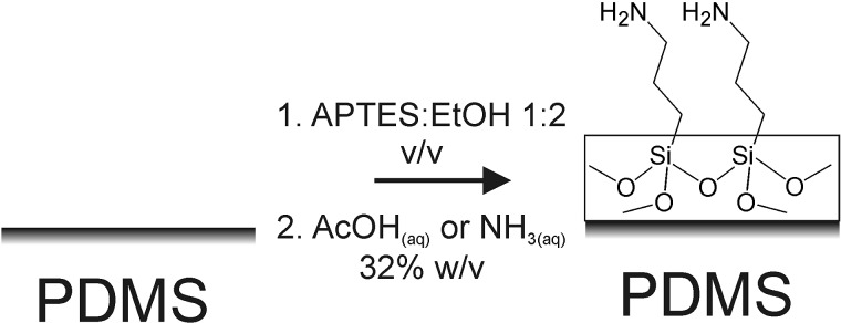
Furthermore, the method is easily extended to the use of substituted alkoxysilanes. In particular, using the alkylamine-substituted silica precursor 3-aminopropyltriethoxysilane (APTES) enables the option of incorporating amine functionality at the PDMS surface (see Fig. 1 for reaction scheme). This opens a route for the facile derivatization of the modified PDMS surface with small organic molecules or biomolecules, in a manner analogous to the use of silanized glass or metal oxide substrates.25, 26
Figure 1.
Scheme of modification of PDMS surface by acid- or base-hydrolysis of APTES.
The methodology offers significant advantages, including reduced reaction times and equipment requirements compared to methodologies which require migration of silica precursors throughout the PDMS bulk19 or oligomerization of the precursor solution before deposition.12 This method is suitable for use in assembled microchannels, thereby allowing the treatment of specific channels within a microfluidic device by injecting the precursor and catalyst solutions through appropriately placed inlets. Alternatively, the treatment can be performed on the open surfaces of PDMS blocks followed by assembly, thereby allowing the rapid treatment of entire devices. Batch processing in this fashion helps to ensure reproducibility in device performance. The simplicity of this fast and inexpensive approach renders it scalable, and suitable for commercial adoption.
METHOD
Deionized water (18.2 MΩ cm−1) was supplied by a Barnstead easypure® RoDI system, and used to prepare all aqueous solutions. Absolute ethanol (>99.85%, PureScience) was used to prepare alkoxysilane solutions. Potassium hydrogen phosphate (≥98%), potassium dihydrogen phosphate (≥98%), and boric acid (≥99.5%) were from Sigma-Aldrich, and sodium acetate trihydrate (AR) was from PureScience. Acetonitrile (HPLC grade) and ammonia solution (32%) were from Scharlau, acetic acid (≥99.5%) was from Panreac, PDMS (Sylgard® 184) was from Dow-Corning, 3-aminopropyltriethoxysilane (APTES, ∼96%,) and naphthalene-2,3-dicarboxaldehyde (NDA) were from Fluka, potassium cyanide (97%) was from BDH, SU-8 (2015) photoresist was from Microchem, tetraethoxysilane (TEOS, 98+%) was from Lancaster. All chemicals were used as received.
Potassium phosphate buffer (pH 7.2, 20 mM) was prepared by dissolving potassium hydrogen phosphate (0.53 g, 3 mmol) and potassium dihydrogen phosphate (0.26 g, 2 mmol) in deionized water (250 ml). Sodium acetate buffer (pH 5.1, 50 mM) was prepared by dissolving sodium acetate trihydrate (6.8 g, 50 mmol) in deionized water (1 l) and adjusting to pH 5.1 with 1 M hydrochloric acid. Borate buffer (50 mM, pH 9.0) was prepared by dissolving boric acid (1.5 g, 2.5 mmol) in deionized water (500 ml), and adjusting to pH 9.0 with 1 M sodium hydroxide solution.
All solutions introduced into PDMS microchannels were filtered through a 0.45 μm regenerated cellulose syringe filter.
Fabrication of PDMS microchannels
Microfluidic channels with a 100 μm by 20 μm cross-section and 3 cm length were fabricated in PDMS using a standard lithographic method.27 Briefly, microfluidic masters were obtained by direct laser writing a pattern into SU-8 photoresist spin-coated onto a PMMA substrate. A Microtech LW405A direct laser writer was prototyped with a dual laser system, including a 375 nm laser specifically for writing in SU-8. Further details of the method will be given in a future publication.28 After development of the pattern, PDMS was cast onto the master, and cured at 100 °C for 1 h. The patterned PDMS channels were removed from the master, and wells were cut at the channel ends with a 3 mm biopsy punch. The channel was placed against a PDMS cover piece, and light pressure was applied with a blunt metal implement (e.g., the back of a scalpel blade) in order to produce a water-tight, conformal seal. The two PDMS sections could be reversibly sealed and easily peeled apart.
Surface modification of PDMS microchannels
Surface modification of PDMS microchannels can be conducted either on assembled PDMS microchannels, or on open-faced microchannels and flat substrates. Surface modification was conducted with either TEOS or APTES as the silica precursor.
TEOS-modification assembled PDMS microchannels
TEOS:ethanol solution (1:2 v/v) was loaded into the assembled microchannel by filling one reservoir with solution and applying vacuum to the other end. The solution was left in place for a period of 15 min to allow diffusion of TEOS into the channel surface. The remaining solution was then removed by the application of vacuum to one end of the channel. The microchannel assembly was then dried in vacuo for 1 min. Aqueous catalyst solution (33% w/v aqueous acetic acid [acid catalyst] or 32% w/v aqueous ammonia solution [base catalyst]) was introduced into the microchannel and left for 3 min to catalyze hydrolysis of TEOS. The catalyst solution was removed and the microchannel assembly was dried in vacuo for 1 min.
-
✓
After surface modification, modified PDMS is preferably left overnight under ambient conditions before further steps, to allow for complete drying and condensation of the silica precursor. Before first use, channels are preferably flushed with a continuous flow of deionized water for 5 min to remove any residue adhering to the channel walls.
APTES-modification of assembled PDMS microchannels
APTES:ethanol solution (1:2 v/v) was loaded into the assembled microchannel and was left in place for a period of 5 min to allow APTES to diffuse into the channel surface.
-
☞
Note that the absorption step is limited to a shorter duration than for TEOS, as there was a tendency for precipitate to form over longer durations.
The remaining solution was then removed by the application of vacuum to one end of the channel. Aqueous catalyst solution (as above) was introduced into the microchannel and left for 3 min.
-
◻
It is important to flush the channel with aqueous catalyst solution as soon as the remaining APTES solution is removed in order to avoid the formation of blockages in the microchannel.
After 3 min, aqueous catalyst solution was removed from the microchannel by the application of vacuum to one end, followed by drying of the entire assembly in vacuo for 1 min.
-
✓
After surface modification, modified PDMS is preferably left overnight under ambient conditions before further steps, to allow for complete drying and condensation of the silica precursor. Before first use, channels are preferably flushed with a continuous flow of deionized water for 5 min to remove any residue adhering to the channel walls.
Surface modification procedure for open channels or flat substrates
Open-face channels or flat substrates of PDMS were modified by immersing them in the ethanolic alkoxysilane solutions for the allotted duration (5 min for APTES:ethanol 1:2 v/v, 15 min for TEOS:ethanol 1:2 v/v). The blocks were then drained, patted dry with a non-lint laboratory wipe, and immersed in an acid catalyst or a base catalyst solution (as above) for 3 min, before draining and drying in vacuo for 1 min.
-
☞
Flushing the microchannels with deionized water before use was found to be unnecessary for channels modified using this procedure.
Plasma treatment for permanent bonding of PDMS channels
Plasma treatment of PDMS was used to affect bonding of TEOS- or APTES-modified PDMS to (modified) PDMS or glass. Modified PDMS blocks were exposed to oxygen plasma generated with an Advanced Energy RFX-600 RF generator attached to a Technics mass flow unit, using the following parameters: 20 s exposure to plasma generated with 20 W power at an RF frequency of 13.56 MHz and with an oxygen pressure of 140 Pa. Immediately after plasma treatment, the treated surfaces were pressed into contact, then left for at least 1 h for the bond to form. The treatment was identical for TEOS- or APTES-modified PDMS.
Characterization procedures
FTIR spectra were measured on a Perkin-Elmer Spectrum One spectrometer with a diamond/ZnSe attenuated total reflectance (ATR) sampling accessory. Typical spectra were collected with 16 scans at a resolution of 4 cm−1, with the PDMS block held against the prism with a standardized pressure. Difference spectra were generated by subtracting a background spectrum of unmodified PDMS.
Electroosmotic flow measurements on the microchannels were carried out using the current monitoring method29 with a combination of either 15/20 mM potassium phosphate buffer (pH 7.2) or else 37/50 mM sodium acetate buffer (pH 5.1), and an applied voltage of 500 V. The electroosmotic flow was determined by dividing the measured channel length by the time taken to equilibrate the buffer concentration across the channel. The EOF for each device was measured 5 times in succession and reported as the mean of the measurements. The reported uncertainty was the standard deviation of the measurements.
Optical images of the channel were obtained using an Photometrics Cascade 1 K CCD camera attached to a Nikon Diaphot 300 inverted microscope fitted with a halogen lamp (12 V 100 W) for bright field images, and a mercury vapour lamp (100 W) and a filter set designed for 525 nm Quantum Dots (Omega Optical, λex ≈ 355–405 nm, λem ≈ 510–540 nm) for epifluorescence imaging. NDA-derivatization of APTES–PDMS was performed with an NDA working solution, which was prepared immediately prior to use by mixing NDA (20 mM in acetonitrile), potassium cyanide (20 mM, aqueous), and pH 9.0 borate buffer in a 1:1:1 ratio (v/v). Measurements of the fluorescence of NDA-derivatized APTES–PDMS were made with the Nikon Diaphot microscope, or in the case of flat APTES–PDMS substrates, with a Molecular Devices SpectraMax M4 platereader.
Static contact angle measurements were made using a KSV CAM200 apparatus. 3 μl drops of deionized water were deposited onto PDMS substrates, and Young-Laplace fittings were made on a series of images of the sessile drops using the KSV CAM200 software suite. SEM measurements were either made on a LEO440 SEM on samples sputter coated with platinum, or on uncoated samples on an FEI Quanta 450 SEM operating at low vacuum (100 Pa).
RESULTS
In contrast to the surface modification procedure of Roman et al.,19 where neat TEOS was allowed to diffuse throughout the entirety of the microchannel assembly from the external surface inwards towards the microchannel; in the procedure presented here, TEOS or APTES was allowed to diffuse directly into the microchannel surface from ethanolic solution. The modification was restricted to the surface, rather than the bulk of the PDMS, by the use of an aqueous catalyst solution to promote hydrolysis of the alkoxysilane at the interface of the PDMS and catalyst solution. Diluting the alkoxysilane precursors with ethanol, and limiting the uptake time served to avoid the swelling and irreversible distortion caused by the rapid migration of neat alkoxysilanes into the pores of PDMS,30, 31 and in the case of APTES avoided the formation of precipitate within the channel. An alkoxysilane:ethanol ratio of 1:2 v/v and uptake times of 5 min for APTES and 15 min for TEOS were found to be optimal.
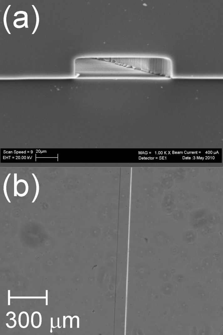
As shown in an SEM micrograph and in an optical micrograph (Figs. 2a, 2b, respectively), the APTES-modified channel is undistorted and retains a rectangular cross section. To aid comparison, further SEM and optical micrographs of native, APTES-modified and TEOS-modified PDMS microchannels are shown in the supplementary material (Fig. S1).32 SEM micrographs of the surface of PDMS cast on a silicon wafer and then modified are also shown in supplementary material (Fig. S2), demonstrating that the surface morphology of modified PDMS appears unchanged at the micron scale.32 Measurements of the transmittance of APTES-modified PDMS microchannels (data not shown) show that modification does not affect the transparency of the channel in the UV-Vis region of the spectrum.
Figure 2.
(a) SEM micrograph and (b) optical micrograph of APTES-modified PDMS microchannels of 100 μm width.
The aqueous catalyst solutions served to hydrolyze the alkoxysilanes at the interface with PDMS, as well as remove excess alkoxysilane from the surface. Drying in vacuo for 1 min was sufficient to remove solvent residues and any remnants of the volatile acid/base. Subsequent washing of the channel with deionized water for 5 min was sufficient to remove any residues, and leave a clean surface which supported a stable rate of EOF (as demonstrated below).
The modification process is rapid, with the reaction carried out in less than half an hour, although an additional 24 h period was allowed for complete drying and condensation of the silica surface.
This process is amenable to the modification exclusively of areas of interest by injection of the requisite solutions through appropriately positioned inlet/outlet reservoirs in fully assembled microchannels. Equally, the method can be easily adapted to modify both open-faced portions of the disassembled channel separately, as the presence of the modified layer does not appear to inhibit adhesion between the PDMS blocks or the formation of a conformal seal, and as such the channel is watertight even under a slight applied pressure. This latter procedure renders the technique amenable to scale-up, as it is simple, rapid and requires only basic equipment.
Plasma treatment can be used to affect permanent sealing of modified PDMS channels to PDMS or glass. Both APTES- and TEOS-modified PDMS bonded strongly to native PDMS, modified PDMS or glass, such that when force was exerted on a plasma-bonded modified PDMS assembly, the PDMS would fail before the bonded sections delaminated.
ATR-FTIR measurements
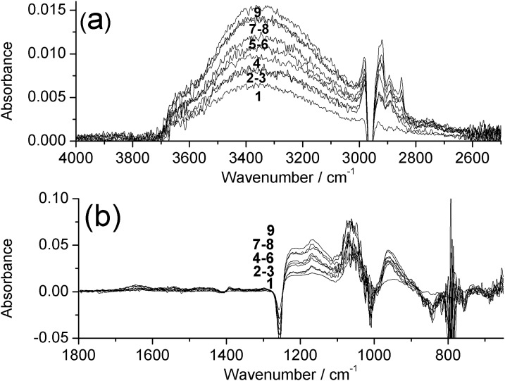
ATR-FTIR measurements were performed to characterize the chemical nature of the modification of the PDMS surface layer. Due to the chemical similarities between PDMS and silica, there is substantial overlap of characteristic bands in the Si-O stretching and bending regions of the infrared spectrum.33 As the silicaceous modification does not fully obscure the signal from the underlying PDMS, in order to highlight the changes occurring upon silica deposition, a background spectrum of unmodified PDMS was subtracted to generate difference spectra, and the effect of sequential cycles of TEOS-modification was investigated. Shown in Fig. 2 are spectra of PDMS with between 1 and 9 cycles of modification with TEOS. In Fig. 3a, a broad band centered around 3350 cm−1 is assigned to the O–H stretch of surface silanol groups, and can be seen to increase in intensity with increasing numbers of coatings. Superimposed upon this is a trough at 2960 cm−1 due to obscuring of the asymmetric C–H stretch of PDMS. In Fig. 3b, troughs can be seen at 1412, 1255, and 790 cm−1, due to obscuring of the asymmetric C–H deformation, symmetric C–H deformation, and Si–C stretch of PDMS, respectively.34 The broad peaks between 1240–1020 and 980–880 cm−1 are assigned to Si–O stretches of the silicaceous layer, and can be seen to increase in intensity with an increasing number of coatings.
Figure 3.
ATR-FTIR difference spectra of base-catalyzed TEOS-modified PDMS with 1–9 coatings between (a) 4000–2500 cm−1 and (b) 1800–650 cm−1. Measured against a background of native PDMS.
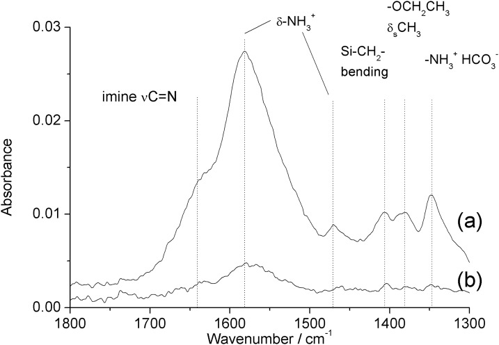
Figure 4 shows the infrared spectrum of PDMS substrates with base- and acid-catalyzed deposition ((a) and (b), respectively) between 1300 and 1800 cm−1. See supplementary material for tabulated assignments of observed infrared bands, Table I.32 Base-catalyzed APTES-PDMS displays a strong band at 1580 cm−1 and weak bands at 1470 and 1350 cm−1 assigned to deformation modes of protonated primary amine groups, and the amine-bicarbonate salt formed by reaction with atmospheric CO2, respectively.35, 36 The shoulder near 1640 cm−1 is assigned to the carbon-nitrogen stretch of an imine formed by oxidation of the aminopropyl moiety.35 These bands confirm the presence of amine groups at the PDMS surface. In addition, there are weak peaks observable at 1406 cm−1 and 1380 cm−1 assigned to the Si–CH2 bending mode of the alkylsilane, and the symmetric deformation mode of the terminal methyl groups of the alkoxysilane moieties of APTES, respectively.
Figure 4.
ATR-FTIR difference spectra (1300–1800 cm−1) of (a) base-catalyzed and (b) acid-catalyzed APTES-modified PDMS measured against a background of native PDMS.
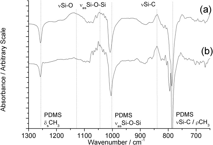
Acid-catalyzed APTES–PDMS displays similar bands, but at a far lower intensity. Figure 5 shows the infrared spectrum between 650 and 1300 cm−1. Both base- and acid-catalyzed APTES–PDMS display several bands of decreased absorbance relative to the native PDMS background due to obscuring of the PDMS surface by the APTES surface modification. These include the PDMS methyl deformation mode at 1257 cm−1, the asymmetric Si–O–Si stretch at 1010 cm−1, and methyl rocking mode/Si–C stretch at 790 cm−1.34 Both samples also display new bands centered around 1130, 1040, and 840 cm−1 due to the Si-O, asymmetric Si–O–Si, and Si–C stretches of condensed APTES, respectively.35 See supplementary material for the full infrared spectra of base- and acid-catalyzed APTES-PDMS between 650 and 4000 cm−1 (Fig. S3).32 Base-catalyzed APTES–PDMS displays a prominent, broad band between 2600 and 3700 cm−1, similar to that observed for TEOS-PDMS, and assigned to the silanol νO–H stretch, superimposed with amine νΝ–Η stretching modes. These observations indicate the formation of an amine-functionalized silicaceous layer at the PDMS surface.
Figure 5.
ATR-FTIR difference spectra (650–1300 cm−1) of (a) base-catalyzed and (b) acid-catalyzed APTES-modified PDMS measured against a background of native PDMS.
Reactivity of amine-functionalized surface of APTES-modified PDMS
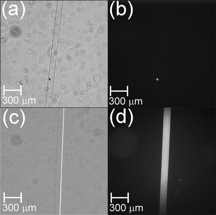
In order to ascertain whether aminopropyl groups in the APTES-PDMS were available for conjugation, APTES–PDMS was derivatized with NDA. NDA reacts with primary amines in the presence of cyanide to form highly fluorescent N-substituted 1-cyanobenz[f]isoindole derivatives (λex = 420 nm, λem = 490 nm).37, 38 The relative fluorescence intensity (RFI) at 490 nm of NDA-derivatized acid-catalyzed APTES–PDMS was only approximately 10% that of base-catalyzed APTES–PDMS, which was consistent with the relative intensities of the amine bands in the ATR-FTIR spectra of acid- and base-catalyzed APTES–PDMS. See supplementary material for a graph of RFI values (Fig. S4).32 Base-catalyzed APTES–PDMS substrates which had been washed with deionized water for 10 min before NDA treatment displayed no significant change in RFI compared to unwashed APTES–PDMS. This indicates that the condensed APTES layer forms an integral part of the surface, and is not removed by washing. Figure 6 shows bright field and epifluorescence images of NDA-derivatized microchannels of native PDMS (Figs. 6a, 6b) and base-catalyzed APTES–PDMS (Figs. 6c, 6d). These show that base-catalyzed APTES–PDMS reacts with NDA/cyanide to form a highly fluorescent product. The greater fluorescence intensity visible in the central portion of Fig. 6d is an artefact due to variation in the illumination intensity across the image, rather than an inconsistency in the coating of the channel.
Figure 6.
Optical micrographs (4× objective) of NDA-derivatized 100 μm-wide PDMS microchannels: bright field images of (a) native PDMS and (c) base-catalyzed APTES–PDMS; epifluorescence images of (b) native PDMS and (d) base-catalyzed APTES–PDMS.
These observations confirm that aminopropyl groups at the surface of APTES-modified PDMS can participate in a reaction typical of primary amines. Work is continuing on the use of these surface aminopropyl groups for the covalent attachment of biomolecules to APTES–PDMS.
Surface and structural properties
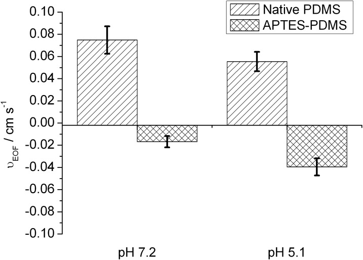
EOF measurements were made on base-catalyzed APTES–PDMS and native PDMS microchannels using pH 7.2 and 5.1 buffers, and the results are summarized in Fig. 7. Positive values of νEOF denote flow towards the cathode and negative values denote flow towards the anode. Native PDMS with its negative surface charge supports EOF towards the cathode.39 It can be seen that at both pH values investigated, APTES-modified PDMS microchannels supported EOF in the opposite direction to native PDMS. This is presumed to arise from the presence of net positive charge at the surface originating from the protonation of basic aminopropyl groups. The average νEOF of native PDMS was observed to decrease from 0.075 to 0.055 cm s−1 moving from pH 7.2 to pH 5.1, whereas the average νEOF of APTES–PDMS increased in magnitude from −0.017 to −0.040 cm s−1. This supports a model of increased positive charge density for APTES–PDMS due to protonation of aminopropyl groups, and decreased net negative charge density for native PDMS due to protonation of surface silanol groups at acidic pH values.
Figure 7.
EOF rates of native and APTES-modified PDMS microchannels at pH 7.2 and pH 5.1. Positive values denote flow towards the cathode and negative values denote flow towards the anode.
The TEOS modification of PDMS microchannels was catalyzed through one of two routes—aqueous acid or aqueous base. Application of a silica coating via the TEOS precursor under acid-catalyzed conditions led to an increase in the EOF rate of approximately 40%, whereas the base-catalyzed coating led to a larger increase in EOF rate of approximately 80% over the native PDMS value at pH 7.2.
TEOS-modified PDMS devices were shown to be stable and demonstrated consistent EOF rates over extended periods. In contrast to plasma-treated PDMS, which typically displays hydrophobic recovery within 1 h,5 the EOF rate of a silica-modified device remained unchanged upon retest after more than 200 days’ inactivity stored in air. In addition, devices displayed consistent EOF upon continued reuse, which is an important consideration for the storage shelf-life of analytical microfluidic devices. The intradevice coefficient of variation (CV) for an acid-catalyzed TEOS-modified device was 5% in 6 sets of 5 measurements each, performed over a period of 21 days.
Wetting contact angle (WCA) measurements performed on native and modified PDMS substrates showed a small, but statistically significant decrease (p < 0.01) from 118 ° ± 2° for native PDMS, to 112° ± 3° and 113° ± 1° for acid- and base-catalyzed TEOS-modified PDMS, respectively. APTES-modified PDMS displayed yet smaller WCAs of 107 ° ± 2° and 105° ± 1° for acid- and base-catalyzed deposition, respectively. These decreases in WCA indicate that modification of PDMS with alkoxysilanes decreases the hydrophobicity of the polymer surface. The WCA measured for native PDMS was relatively large compared to some literature values (118° ± 2° cf. 108.5°)19 indicating the possible contribution of surface roughness to the measured WCA.
CONCLUSIONS
Treatment of PDMS with ethanolic solutions of the alkoxysilanes, APTES, and TEOS, followed by application of aqueous acid or base catalyst, resulted in the formation of an integral silicaceous surface, without distortion of the dimensions of the underlying PDMS. Aqueous ammonia solution was a more effective catalyst for deposition of APTES than was acetic acid, and led to amine-functionalized surfaces with a greater reactivity. TEOS- and APTES-modified PDMS had smaller WCAs than native PDMS, which is indicative of reduced hydrophobicity. TEOS modification of PDMS microchannels was demonstrated to increase and stabilize the EOF rate. This effect was not transitory, in contrast to plasma treatment.
The methodology presented here represents a rapid technique for modifying PDMS surfaces, which can be used to treat specific areas of a microfluidic device or applied generally to the entire device, in a manner which is easily scalable. Work is continuing on the use of APTES-modified PDMS surfaces to covalently immobilize biomolecules, in an active form, on the surfaces of microfluidic channels.
ACKNOWLEDGMENTS
This work was supported by grant C08X0806 from the New Zealand Ministry of Science and Innovation.
References
- Auroux P. A., Iossifidis D., Reyes D., and Manz A., Anal. Chem. 74, 2637 (2002). 10.1021/ac020239t [DOI] [PubMed] [Google Scholar]
- Reyes D. R., Iossifidis D., Auroux P. A., and Manz A., Anal. Chem. 74, 2623 (2002). 10.1021/ac0202435 [DOI] [PubMed] [Google Scholar]
- Henares T. G., Mizutani F., and Hisamoto H., Anal. Chim. Acta 611, 17 (2008). 10.1016/j.aca.2008.01.064 [DOI] [PubMed] [Google Scholar]
- McDonald J. C. and Whitesides G. M., Acc. Chem. Res. 35, 491 (2002). 10.1021/ar010110q [DOI] [PubMed] [Google Scholar]
- Duffy D. C., McDonald J. C., Schueller O. J. A., and Whitesides G. M., Anal. Chem. 70, 4974 (1998). 10.1021/ac980656z [DOI] [PubMed] [Google Scholar]
- Wong I. and Ho C. M., Microfluid. Nanofluid. 7, 291 (2009). 10.1007/s10404-009-0443-4 [DOI] [PMC free article] [PubMed] [Google Scholar]
- Zhou J., Ellis A. V., and Voelcker N. H., Electrophoresis 31, 2 (2010). 10.1002/elps.200900475 [DOI] [PubMed] [Google Scholar]
- Makamba H., Kim J. H., Lim K., Nokyoung P., and Hahn J. H., Electrophoresis 24, 3607 (2003). 10.1002/elps.200305627 [DOI] [PubMed] [Google Scholar]
- Lovchik R. D., Wolf H., and Delamarche E., Biomed. Microdevices 13, 1027 (2011). 10.1007/s10544-011-9572-0 [DOI] [PubMed] [Google Scholar]
- Toepke M. W. and Beebe D. J., Lab Chip 6, 1484 (2006). 10.1039/b612140c [DOI] [PubMed] [Google Scholar]
- Gomez-Sjoberg R., Leyrat A. A., Houseman B. T., Shokat K., and Quake S. R., Anal. Chem. 82, 8954 (2010). 10.1021/ac101870s [DOI] [PMC free article] [PubMed] [Google Scholar]
- Abate A. R., Lee D., Do T., Holtze C., and Weitz D. A., Lab Chip 8, 516 (2008). 10.1039/b800001h [DOI] [PubMed] [Google Scholar]
- Kartalov E. P., Anderson W. F., and Scherer A., J. Nanosci. Nanotechnol. 6, 2265 (2006). 10.1166/jnn.2006.504 [DOI] [PubMed] [Google Scholar]
- Vickers J. A., Caulum M. M., and Henry C. S., Anal. Chem. 78, 7446 (2006). 10.1021/ac0609632 [DOI] [PubMed] [Google Scholar]
- Luo Y., Huang B., Wu H., and Zare R. N., Anal. Chem. 78, 4588 (2006). 10.1021/ac052274g [DOI] [PubMed] [Google Scholar]
- Plecis A. and Chen Y., Microelectron. Eng. 84, 1265 (2007). 10.1016/j.mee.2007.01.276 [DOI] [Google Scholar]
- Dimov I. K., Riaz A., Ducrée J., and Lee L. P., Lab Chip 10, 1468 (2010). 10.1039/b925132d [DOI] [PubMed] [Google Scholar]
- Abate A. R., Krummel A. T., Lee D., Marquez M., Holtze C., and Weitz D. A., Lab Chip 8, 2157 (2008). 10.1039/b813405g [DOI] [PubMed] [Google Scholar]
- Roman G. T., Hlaus T., Bass K. J., Seelhammer T. G., and Culbertson C. T., Anal. Chem. 77, 1414 (2005). 10.1021/ac048811z [DOI] [PubMed] [Google Scholar]
- Orhan J. B., Parashar V. K., Flueckiger J., and Gijs M. A. M., Langmuir 24, 9154 (2008). 10.1021/la801317x [DOI] [PubMed] [Google Scholar]
- Yang K. S., Clementz P., Park T. J., Lee S. J., Park J. P., Kim D. H., and Lee S. Y., Curr. Appl. Phys. 9, e66 (2009). 10.1016/j.cap.2008.12.032 [DOI] [Google Scholar]
- Wu H.-L., Yang P.-Y., Fan G.-R., Tian Y.-P., Lu H.-J., and Jin H., Chin. J. Chem. 24, 903 (2006). 10.1002/cjoc.200690172 [DOI] [Google Scholar]
- Suzuki Y., Yamada M., and Seki M., Sens. Actuators, B 148, 323 (2010). 10.1016/j.snb.2010.04.018 [DOI] [Google Scholar]
- Hench L. L. and West J. K., Chem. Rev. 90, 33 (1990). 10.1021/cr00099a003 [DOI] [Google Scholar]
- Weetall H. H., Biochem. J. 117, 257 (1970). [DOI] [PMC free article] [PubMed] [Google Scholar]
- Weetall H. H. and Hersh L. S., Biochim. Biophys. Acta 206, 54 (1970). 10.1016/0005-2744(70)90081-1 [DOI] [PubMed] [Google Scholar]
- Bubendorfer A., Liu X., and Ellis A. V., Smart Mater. Struct. 16, 367 (2007). 10.1088/0964-1726/16/2/015 [DOI] [Google Scholar]
- Bubendorfer A., Thomas S., Kemp R., and Arnold W. M., “ Laser direct writing of SU-8” (unpublished).
- Huang X., Gordon M. J., and Zare R. N., Anal. Chem. 60, 1837 (1988). 10.1021/ac00168a040 [DOI] [PubMed] [Google Scholar]
- McDonald J. C., Duffy D. C., Anderson J. R., Chiu D. T., Wu H., Schueller O. J. A., and Whitesides G. M., Electrophoresis 21, 27 (2000). [DOI] [PubMed] [Google Scholar]
- Lee J. N., Park C., and Whitesides G. M., Anal. Chem. 75, 6544 (2003). 10.1021/ac0346712 [DOI] [PubMed] [Google Scholar]
- See supplementary material at http://dx.doi.org/10.1063/1.4740232 for SEM and optical micrographs of native and modified PDMS microchannels and surfaces; tabulated assignments of infrared bands observed for APTES–PDMS; the full infrared spectra of base- and acid-catalyzed APTES-PDMS between 650 and 4000 cm−1; and a graph of the relative fluorescent intensity of NDA derivatized acid and base catalyzed APTES-PDMS.
- Socrates G., Infrared and Raman Characteristic Group Frequencies (John Wiley & Sons, Chichester, 2001), p. 241. [Google Scholar]
- Morvan J., Camelot M., Zecchini P., and Roques-Carmes C., J. Colloid Interface Sci. 97, 149 (1984). 10.1016/0021-9797(84)90282-0 [DOI] [Google Scholar]
- Kim J., Seidler P., Wan L. S., and Fill C., J. Colloid Interface Sci. 329, 114 (2009). 10.1016/j.jcis.2008.09.031 [DOI] [PubMed] [Google Scholar]
- Socrates G., Infrared and Raman Characteristic Group Frequencies (John Wiley & Sons, Chichester, 2001), p. 107. [Google Scholar]
- Carlson R. G., Srinivasachar K., Givens R. S., and Matuszewski B. K., J. Org. Chem. 51, 3978 (1986). 10.1021/jo00371a013 [DOI] [Google Scholar]
- De Montigny P., Stobaugh J. F., Givens R. S., Carlson R. G., Srinivasachar K., Sternson L. A., and Higuchi T., Anal. Chem. 59, 1096 (1987). 10.1021/ac00135a007 [DOI] [PubMed] [Google Scholar]
- Wheeler A. R., Trapp G., Trapp O., and Zare R. N., Electrophoresis 25, 1120 (2004). 10.1002/elps.200305784 [DOI] [PubMed] [Google Scholar]


