Abstract
To increase image acquisition efficiency, we develop alternative gradient encoding strategies designed to provide spatial encoding complementary to the spatial encoding provided by the multiple receiver coil elements in parallel image acquisitions. Intuitively, complementary encoding is achieved when the magnetic field encoding gradients are designed to encode spatial information where receiver spatial encoding is ambiguous, for example, along sensitivity isocontours. Specifically, the method generates a basis set for the null space of the coil sensitivities with the singular value decomposition (SVD) and calculates encoding fields from the null space vectors. A set of nonlinear gradients is used as projection imaging readout magnetic fields, replacing the conventional linear readout field and phase encoding. Multiple encoding fields are used as projections to capture the null space information, hence the term Null Space Imaging (NSI). The method is compared to conventional Cartesian SENSitivity Encoding (SENSE) as evaluated by mean squared error and robustness to noise. Strategies for developments in the area of nonlinear encoding schemes are discussed. The NSI approach yields a parallel imaging method that provides high acceleration factors with a limited number of receiver coil array elements through increased time efficiency in spatial encoding.
Keywords: nonlinear gradient encoding, singular value decomposition, parallel imaging, receiver coil complementarity, accelerated imaging
INTRODUCTION
Parallel imaging accelerates scan times by sharing the spatial localization duties between the magnetic encoding fields and a receiver coil array (1,2). In a conventional Cartesian Fourier reconstruction, orthogonal linear x- and y- gradients are used, with the number of phase encoding steps determining the acquisition time. The acquired k-space data represents a collection of coefficients specifying Fourier basis functions. For Cartesian parallel imaging, reconstruction starts from an undersampled k-space data set whose reduced k-space coverage leads to aliasing. Aliasing may be unwrapped through knowledge of the aliased pixels in the spatial domain (SiMultaneous Acquisition of Spatial Harmonics SMASH and SENSE) or filling in missing k-space coefficients from a local neighborhood (Generalized Auto-calibrating Partially Parallel Acquisition GRAPPA) (3–5).
The use of acquired parallel data to unwrap aliasing artifacts in the image domain or spatial domain has been extensively studied (6). In one generalization, the set of applied linear gradients can be collected into a matrix equation where an encoding matrix acts on the spin density vector to produce data. Repeated small matrix inversions can be performed to solve for individual pixels in a SENSE-like reconstruction (7). In general, these un-aliasing techniques, as evaluated through noise amplification metrics such as geometry factor (g-factor) maps in SENSE, improve as the number of receiver coil elements increase (8).
The development of coil arrays with more and more receiver elements has chiefly driven increases in acceleration factor. However, increasing the number of receiver coils faces diminishing returns due to both increasing cost and coupling issues associated with more and smaller coils. The NMR phased array designed by Roemer et. al. used overlapping coils and low input impedance preamplifiers to eliminate mutual inductance and interference respectively (9). Computer modeling of SNR by Lawry et. al. showed that while small surface coils provide improved SNR at regions close to the coil, large coils improve B1 uniformity and SNR at depth (10). Recently, a state-of-the-art array featured 128 hexagonally overlapping loops to mitigate inductive coupling, bazooka baluns for transmission line impendence matching, and resonant common mode traps (11). While there have been significant advances in receiver coil arrays, uniform mode acquisitions have spatially homogeneous SNR, reduced transmission line losses, and reduced hardware failure. The ability to perform parallel imaging provides a strong incentive to use coil arrays, but may not be enough of an incentive to balance the increasing costs associated with higher element counts. The work presented here attempts to improve acceleration factors, not by adding more coil elements, but through reconsideration of the shared responsibilities of spatial encoding performed by the magnetic field gradients and the receiver coil arrays. This work attempts to directly link the spatial encoding provided by the receiver coils and the magnetic field gradients to design a more efficient encoding strategy.
The overarching premise of this work is that if one is to perform parallel imaging and thus use the receiver coil sensitivity profiles to perform some spatial encoding, then phase encoding and linear readout magnetic field gradients may not represent the best approach to complement the spatial information provided by the receiver coils. For example, in the case of a circumferential receiver coil array, the nonlinear receiver sensitivity profiles suggest rotationally symmetric magnetic field encoding gradients for encoding fields designed to disambiguate coil sensitivity isocontours, and efficiency gains have been demonstrated with such a system via O-space imaging (12)
Both O-space imaging and PatLoc imaging (13–15), have demonstrated the utility of nonlinear encoding fields. PatLoc imaging was developed as a means to reduce peripheral nerve stimulation during gradient ramping through the use of arbitrary orthogonal nonlinear encoding fields with the added advantage of increased peripheral resolution. O-space imaging uses the Z2 spherical harmonic field, where Z2 is short-hand for , to image with an encoding field that is complementary to the coil sensitivities, but with field shapes optimized through manual search. O-space imaging moves the center placement of the Z2 gradient using linear x-and y- encoding fields to form different projections that complement the coil sensitivities.
This work introduces a more generalized form of O-space imaging where the encoding gradients are now designed directly from the coil sensitivity profiles. More specifically, the gradient encoding fields form a set of fields that span the null space of the receiver sensitivity profiles, and hence the term Null Space Imaging (NSI). This leads to a projection imaging approach that uses a combination of linear and higher order spherical harmonic encoding fields for spatial encoding. These fields, derived from the coil sensitivity profiles, form a set of projection gradients that have varying spatial patterns. Each echo, instead of having different phase encoding as in Cartesian SENSE, now has a different projection gradient selected from the set spanning the null space of the receiver coils. In NSI, the user begins with a receiver coil array designed for parallel imaging applications and derives a set of projection gradients that are complementary to the spatial encoding provided by the receiver coil array. The number of different projection gradients that are used is equivalent to the number of phase encode gradients used in conventional parallel imaging.
The sharing of encoding duties between the receiver coils and the gradient encoding functions may be formalized using a linear algebra approach. First, a singular value decomposition (SVD) operation divides a matrix composed of the vectorized coil sensitivities into orthonormal matrices, providing information on the action of the operator in algebraic space (16). Lin et. al. performed an SVD on the coil sensitivities and examined the orthogonal column vectors representing the column (range) space to produce orthogonal phase encode and readout gradients for PatLoc imaging (17). While the SVD can derive orthogonal encoding fields for phase encoding and readout, the SVD analysis in NSI creates projection imaging gradient fields covering the null space of the coil array, where spatial information is poorly encoded. In an application of NSI, the design principles need only be applied once for a given receiver coil arrangement, acquisition matrix size and orientation, and then a set of encoding fields can be applied to subsequent imaging sequences with similar parameters.
During the data acquisition, NSI encoding fields encode detail poorly captured by the coil array, namely information residing in the coil array null space. As the feasible encoding shapes in free space must be limited to solutions of Laplace’s equation, ∇2φ = 0 (18), combinations of realizable spherical harmonics are used to approximate the derived encoding functions that in the current formulation may not otherwise be achievable. Spherical harmonics are well-characterized fields that have been realized in past coil designs for B0 shimming (19).
Experimental validation of the NSI approach is shown for data acquired with a pulse sequence analogous to a gradient echo projection imaging sequence, but in this case using a gradient system with a second order Z2 term in addition to the standard linear x- and y-gradients. The performance of NSI is measured relative to Cartesian SENSE through mean squared error (MSE) measurements, noise amplification tests, and point spread function (PSF) maps (20–24). The results demonstrate that NSI enables efficient image acquisition at accelerations exceeding the number of receiver coil elements.
THEORY
Deriving Gradient Encoding Fields
In the following section we define the encoding fields, G, to be used for spatial encoding via projection imaging spanning the null space of the receiver coil profiles matrix, C. The coil sensitivity profiles are first vectorized such that for an Nx x Ny = N imaging matrix and L receiver coils, one forms a L x N matrix C, with each row containing the sensitivity profile for one receiver element. The gradient field matrix G has dimensions K x N, where K represents the total number of echoes observed. An orthogonality constraint used here specifies that the dot product between the coil sensitivity and an ideal encoding shape should be zero. Furthermore, an ideal set of gradient encoding fields would consist of an orthogonal set of gradients such that each gradient field encodes independent information. These two constraints can be written formally as,
| Eq. [1] |
| Eq. [2] |
Here l-th, i-th and k-th represent specific coil and encoding functions respectively, and δik is the Kronecker delta. For example, Gi represents a single readout projection imaging field with dimensions Nx x Ny that imposes phase during an echo as exp(−j2πγGit). In order to determine a set of encoding fields, we find the vectors that are mapped to zero when acted on by the coil sensitivity matrix C. The SVD factorization yields a set of orthogonal vectors that spans the null space of C.
| Eq. [3] |
Here, U and V are factorization matrices with dimensions L x L and N x N respectively, VH denotes the transpose conjugate of V, and Σ is a diagonal matrix containing the singular values with dimensions L x N. By a property of the SVD, the null space V0 is formed by the sub-matrix of V with columns starting after the L-th column. There are many potential sets of fields that span the null space since there is no unique basis set for the vectors that are orthogonal to the coil profiles (the many valid basis sets would be related to each other through a linear transformation), but each basis set covers the null space. In order to generate gradient shapes, the vectors must be interpreted as encoding fields. Taking the argument to solve the set of gradient fields:
| Eq. [4] |
The resulting analysis gives N - L encoding functions. Thus an eight coil (L =8) 128×128 image matrix would yield a set of (128×128) −8 = 16376 encoding magnetic field gradient shapes. It may be difficult to image with all the vectors in the null space, which is for example (128×128) by (128×128 − 8). Instead, using the SVD analysis allows one to find vectors that satisfy the orthogonality constraint (Eqns. 1 and 2) that yield a set of singular value ordered gradient shapes, G. A second decomposition allows the consideration of the column (range) space of G and provides a singular value ordering of the encoding fields as described in the next section.
Encoding Fields
In practice, the SVD of G can be computationally difficult due to the large N x N matrix (e.g. for a 256×256 image, N x N has nearly 4.3 billion elements). This set can be greatly reduced by applying a fast SVD method known as the Lanczos SVD, which provides accurate estimates of orthogonal singular vectors up to 32 using reorthonormalization (25). Only the highest singular values and associated singular vectors are then used as projection imaging gradient fields. The Lanczos SVD of the set of encoding fields matrix, G is:
| Eq. [5] |
Here, Ũ and Ṽ are partial factorization matrices with dimensions N x K, and S is a diagonal matrix containing the relative singular values with dimensions K x K. The number of projections or encoding fields, K, is equivalent in time to the number of phase encode steps to be used in a Cartesian Fourier sequence. The value K is chosen based on the desired acceleration and is an input to the Lanczos SVD. The columns in Ũ approximate the column (range) space of G. The gradient fields defined in the columns in Ũ are used as projection imaging readout gradients in any spin- or gradient- echo sequence, and phase encoding is eliminated.
For physically realizable encoding fields, a set of in-plane spherical harmonics (up to any order, constrained only by the available gradient hardware) can be used to approximate the encoding fields in Ũ using a least squares fit. As a check on this formalism in the limiting case where the coil sensitivity profile is uniform, this NSI approach yields linear fields. The encoding fields derived from the SVD operation above are unconstrained and therefore may contain field transitions or shapes that may not be physically realizable. Thus the field shapes generated by this formalism, while promising, are an approximation to an ideal set of projection imaging gradients.
METHODS
Overview
Once the set of NSI encoding fields are generated according to the procedure outlined above, the encoding fields corresponding to the highest singular values can be selected for imaging. For the work presented below, spherical harmonic magnetic gradient functions, up to second order, were used to approximate the target gradient shapes derived from the SVD. The more gradient shapes the hardware is capable of generating, the better the fit can be to the idealized encoding fields. For the scanner experiments, a Z2 gradient insert from Resonance Research Inc. provided nonlinear imaging capabilities and thus our approximation of the ideal gradient shapes included linear x- and y- gradients and this Z2 term.
Simulations
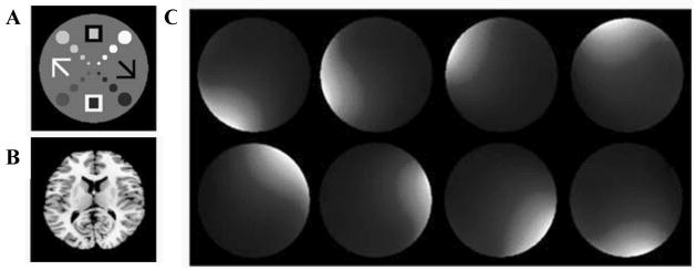
A set of simulated receiver coil sensitivity profiles were derived using analytical expressions for circumferentially arranged microstrip RF detectors (26). The Lanczos SVD described above was implemented in the PROPACK software package (http://soi.stanford.edu/~rmunk/PROPACK/) in MATLAB® (Natick, MA). A range of conditions including different levels of noise, acceleration factors and readout sampling rates were tested. The pulse sequence is shown (Fig. 1). It is a slice-selective spin echo sequence with the phase encoding gradient removed and a different nonlinear imaging gradient for each readout. Each echo represents a projection of the object onto a unique gradient shape. A fully-sampled axial brain image and a specially designed numerical phantom were used (Fig. 2a,b) to generate the spin densities, and simulations performed with the simulated coil sensitivities (Fig. 2c). The numerical phantom contained four contrast levels and was designed with the smallest features towards the center – a region nonlinear methods tend to find challenging to image. The approximation of the ideal NSI gradients used a combination of first and second order, non-degenerate in-plane shapes (all achievable with current gradient technology) as shown in Fig. 3. In all cases, a spin echo sequence was used, phase encoding was eliminated, and the NSI projection imaging gradients were used to dephase and rephase (readout) the spins to form an echo. The image plane was a transverse slice at isocenter. A set of echoes, one for each pulse sequence repetition (TR), was simulated with each echo arising from the application of a different NSI gradient term selected from the set of terms calculated using the SVD process described above.
Fig. 1.
The pulse sequence for Null Space Imaging. The sequence is analogous to a spin echo sequence, but instead of a linear readout gradient, nonlinear encoding fields (G1 to GK) are used as projection imaging gradients. The total number of projections or encoding fields, K, is equivalent to the number of phase encode steps to be used in a typical Cartesian Fourier sequence.
Fig. 2.
(a,b) Numerical phantom and brain images used in the simulations. The phantom has four contrast levels with the smallest features near the center. (c) Sample microstrip array coil sensitivity maps (one for each of the eight strip receivers) used for parallel detection during imaging.
Fig. 3.
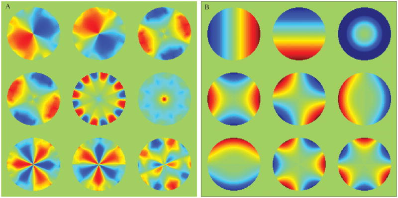
(a) The first nine target encoding shapes generated by NSI for a sixteen element coil array. The target fields are approximated by the gradients in (b) using a least squares fit. (b) A set of magnetic fields used for nonlinear projection imaging up to the second order in-plane non-degenerate fields. From left to right, the spherical harmonics by common names: X, Y, Z2, C2, S2, Z2X, Z2Y, X3, and Y3. Fields are in Tesla normalized from 0 to 1 T, and scaled to satisfy the Nyquist sampling criteria during imaging.
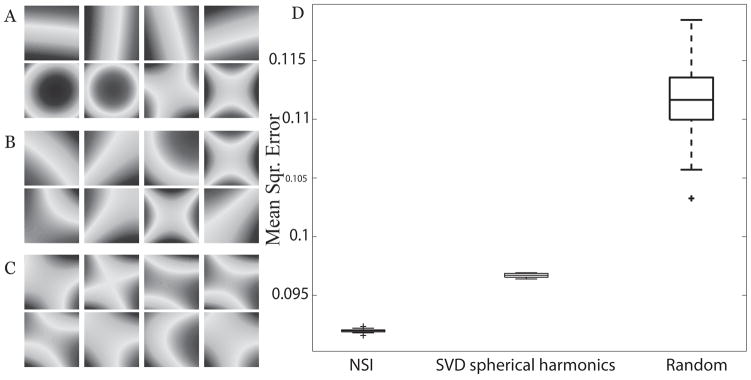
We compared the performance of the NSI method relative to different methods of generating nonlinear gradient terms in addition to testing NSI against Cartesian SENSE encoding. Encoding fields were generated using approximations to fields produced through an SVD on randomly weighted spherical harmonic fields and combinations of spherical harmonics with pseudo-random weighting, samples of which are shown in Fig. 4. The pseudo-random encoding fields were weighted such that linear encoding fields contributed at least 60% of the bandwidth, which improved reconstructions. For the comparison, the SVD was performed on spherical harmonic shapes and the encoding fields corresponding to the highest singular values were approximated. Reconstructions were compared via mean square error (MSE) between the accelerated acquisition reconstruction and the original true image.
Fig. 4.
Several sets of nonlinear encoding shapes were generated to compare different NSI encoding schemes. First and second order gradient shapes generated by (a) approximation to NSI targets, (b) encoding shapes generated from an SVD on randomly-weighted 1st and 2nd order spherical harmonic shapes, and (c) an example of gradients generated with random-weighted spherical harmonics. For the random case, a new gradient set was generated for each trial. Fields are in Tesla normalized from 0 to 1 T. (d) Using the gradient sets of (a), (b), and (c), MSE in the reconstructed image relative to the true image is shown after 20 iterations with random noise added to the image phantom as correlated whole body noise.
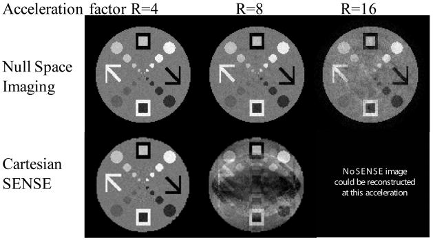
Data for the simulations was generated starting with a base image matrix of 128×128 data points. NSI reconstructions were compared to SENSE reconstructions at acceleration factors of R=4 (32 phase encodes for SENSE and 32 NSI projections for NSI) and R=8 (16 phase encodes for SENSE and 16 NSI projections for NSI) – hence comparisons at each acceleration factor were time-equivalent comparisons. The Cartesian sampled data was generated by applying a 2D FFT to the phantom image and subsampling the data in the phase encode direction according to the reduction factor. Highly accelerated acquisitions with R=16 and 32 were also investigated. At high acceleration factors, Cartesian SENSE imaging cannot reconstruct images due to the number of aliased points exceeding the number of receiver coils. For the accelerated NSI scans, the sampling rate (readout) was held constant at 512 samples. The encoding field strength was calculated such that the frequency bandwidth was at least equal to twice the sampling rate, the Nyquist relation (specifically 2πγ*Gi = 2*Ns/Ts was used).
Whole body Gaussian noise was added to the phantom prior to filtering with the coil sensitivity profiles and hence noise was correlated across the different coil channels. The level of injected noise was chosen as a percentage of the mean intensity in the phantom. Noise amplification in the SENSE reconstructions was tempered using Tikhonov regularization via a truncated SVD of the aliasing matrix (27). Since NSI does not employ conventional phase encoding, the data do not reside in k-space, and a 2D FFT reconstruction approach cannot be used. NSI reconstructions were performed using the Kaczmarz iterative algorithm, an algebraic reconstruction technique (28), which requires only one projection to be processed at a time. Each echo represents a projection of the object along isofrequency contour lines of the particular nonlinear read gradient used in the echo. The method here employs the same reconstruction workflow as previously described for O-space imaging (12).
Further reconstructions explored the possible benefits of increasing the sampling rate of each echo. The NSI readout sampling rate was increased to four times the base rate with noise added to the phantom prior to filtering with the receiver profiles to mimic the increased sampling bandwidth. For image resolution analysis, PSF maps were made by reconstructing point sources on a background of white noise and taking the full width half max of the PSF. With the scanner data, noise was added to the original gradient echo image to test the robustness of the imaging and reconstruction methods.
Imaging Experiments
Imaging experiments were performed on the Siemens 3T Trio scanner using a gadolinium doped water phantom and an orange. A gradient echo imaging experiment was performed using a Z2 gradient insert from Resonance Research Inc. SENSE images were reconstructed using data from the conventional gradient echo acquisition. SENSE images were regularized as described above. Imaging parameters were TE = 10ms, TR = 500 ms, Hz/px = 390, FOV = 10 cm, Ns = 128, slice thickness = 3mm, and flip angle = 30°. The image plane was set as a transverse slice at isocenter. The Z2 gradient from Resonance Research Inc. was triggered using TTL pulses from the Siemens scanner and the gradient waveforms were controlled using a Dynamic Shim Unit controller (29).
To empirically measure the encoding fields with each time point, a chemical shift imaging experiment measured the phase at each time point of an acquisition on a uniform phantom (21–24). The phase images performed on a uniform phantom were used to generate the encoding parameters used in the Kaczmarz reconstruction. Encoding parameters are sequence dependent, rather than object dependent. In practice, the parameters need to be determined for any gradient waveform only once for the given imaging parameters and then these parameters may be used to reconstruct any object. Imaging parameters for measuring the phase induced by the encoding fields were the same as for the imaging experiment except that the TR was shortened to 80 ms. A phantom comprised of various tubes with doped water and an orange were imaged, and these were reconstructed using the encoding parameters acquired on the uniform phantom.
RESULTS
NSI Encoding Fields
In contrast to the linear encoding fields in Cartesian SENSE, the encoding fields generated for NSI possess symmetry that reflects in part the receiver coil sensitivity profile geometry. The NSI target fields before approximation possess a radial symmetry that reflects the coil geometry, namely sectioning the areas demarcated by the coil sensitivity maps (Fig. 3a). The noise simulation results are shown (Fig. 4), which test for stability in MSE with respect to random noise that is added to the phantom. Box plots were generated using 20 sets of random noise with each given gradient set to visualize the MSE. The two SVD methods of calculating the projection field gradient terms have lower MSE as well as smaller variation in the MSE (Fig. 4a,b). NSI is better than the other methods with the range of MSE (visualized as whiskers in the box plot) below the range from the other methods (Fig. 4d). Simulation results of nonlinear imaging compared with several other existing acceleration methods previously have been presented for the case of O-space imaging (12). As NSI was designed to generalize the O-space imaging approach, these comparisons are not duplicated.
SENSE comparison: Noise and Acceleration
Comparisons with SENSE reconstructions illustrate that NSI has lower MSE at high acceleration factors (Fig. 5). At the center, the numerical phantom SENSE reconstructions obscure small lesion-like features. Algebraic reconstruction of the Cartesian parallel imaging acquisition was performed to ensure that this result is not a function of the reconstruction algorithm, but the result, albeit requiring more time, was similar to regularized SENSE reconstructions. The differences become pronounced at high acceleration rates, where g-factor noise amplification dominates.
Fig. 5.
NSI images and regularized Cartesian SENSE images are presented at different acceleration levels for an eight-element coil array. The Cartesian SENSE image shows noise amplification related to the geometry of the coils. No SENSE images are possible at acceleration factors greater than the coil number since the pseudo-inverse reconstructions are ill-conditioned.
High sampling
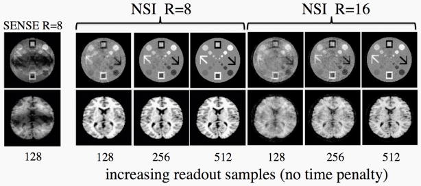
The effect of increasing sampling in the readout direction in NSI is shown (Fig. 6). Due to the 2D variation in nonlinear encoding fields, increasing sampling in the readout leads to additional information in both the in-plane dimensions. The figure shows increasing reconstruction quality for NSI at higher sampling. This is an important advantage as there is no cost in terms of imaging time for this additional sampling as long as the gradients are sufficiently strong. This is not the case with Cartesian SENSE where the fold-over artifacts are in the phase encode direction. Increased sampling in the readout direction does not help with the fold-over artifacts. This represents one of the major advantages of approaches that use frequency encoding in both in-plane directions.
Fig. 6.
Simulations demonstrating the effect of increasing the readout sampling in NSI. Imaging time is held constant. The NSI method benefits from the increase in sampling in the readout due to the 2D nature of the encoding fields whereas in the case of Cartesian sampling there is no reduction in the foldover artifacts with increasing sampling in the readout. With an algebraic construction scheme, additional data contributes information towards the image. In practice, increasing the readout samples is limited by gradient strength and bandwidth or noise issues but the range simulated here is well within reach of clinically relevant gradient amplitudes. This example shows that increased sampling in the readout allows for very high acceleration factors to be obtained while still maintaining excellent image quality.
Resolution Effects
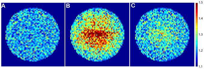
The resolution obtained with NSI is not uniform and thus construction of a simple g-factor map is difficult. The point spread function (PSF) maps for both SENSE, which has constant resolution across the FOV, and NSI, which has variable resolution across the FOV, are shown (Fig. 7). It is clear that SENSE has a sharper PSF that better approximates the ideal delta function at R=4 while the NSI PSF is sharp near the outside edges of the image, where the gradients are sharpest, but suffers from a loss of resolution near the center of the FOV. Much of this loss of sharpness however can be regained by higher sampling in the readout (Fig. 7c), with no time penalty (see also Fig. 6). In practice, there is an SNR limit to this increased readout sampling and this is determined by the magnet strength, pulse sequence, and subject properties.
Fig. 7.
NSI produces images with nonuniform resolution and thus traditional g-factor maps cannot be used to assess different acquisition schemes. Here, point spread function (PSF) maps at R=4 acceleration factor for (A) Cartesian SENSE (where the PSF is constant across the FOV), (B) NSI with Ns =128 (readout sampling), and (C) NSI with Ns = 256. Notably, the PSF map of NSI improves with additional readout sampling due to the nonlinear field encoding in 2D.
Imaging Experiments
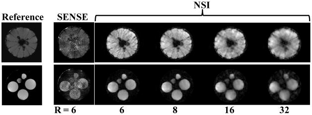
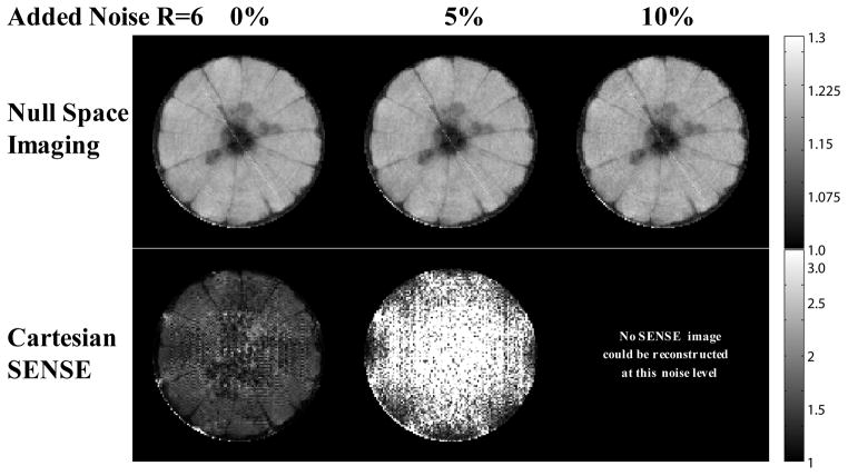
The imaging experimental results for the orange and the tube phantoms are shown (Fig. 8). The reference fully phase-encoded image shows seeds and sections of the orange. In order to show a variety of high acceleration factors, several NSI images are shown along with a SENSE R=6 image. At accelerations above R=6, the SENSE reconstruction amplifies noise that saturates the image and thus SENSE reconstructions for accelerations above R=6 are not shown. For NSI acquisitions at very high acceleration factors, R =16 and R=32, reasonable image quality is preserved although the phantom images begin to degrade and show dispersed artifactual signal outside the tubes. The R = 6 and 8 NSI images show the sections of the orange are distinct and the seeds of the orange near the center of the FOV can be seen. Adding white noise to the data collected further reveals that NSI resolves features better even at high noise levels (Fig. 9). With no added noise, the NSI scan shows some evidence of image degradation at R=6, but individual orange slices still can be resolved. When the noise added reached 10%, the SENSE reconstruction amplified the noise to the extent that no reasonable image could be reconstructed.
Fig. 8.
The first true NSI mages acquired of an orange (top row) and a phantom consisting of multiple tubes containing doped water. A full data set (128×128) was acquired and then higher acceleration factors were made for the NSI data by omitting increasing numbers of projection gradients, e.g. the R = 16 corresponds to the first 8 most significant encoding shapes as determined by the SVD, and by skipping phase encode lines in the SENSE reconstructions. NSI and SENSE are compared at equivalent acquisition times for the R=6 acceleration factor, but no SENSE image could be reconstructed at acceleration factors above 6 so only NSI results are shown.
Fig. 9.
Reconstructions of an orange are shown at R=6 under different levels of additional correlated whole body noise. Noise was added directly to a fully sampled data set. NSI is robust to the noise as it uses an algebraic reconstruction technique, and the noise adds no error to the encoding information. Cartesian SENSE amplifies the noise during matrix inversions for each position. Matrix inversions become ill-conditioned as the acceleration factor approaches the number of coils, and therefore the noise is amplified.
DISCUSSION
The principle goal of NSI is to develop a methodology for designing a gradient encoding scheme that is derived directly from the receiver coil sensitivity profiles in an effort to optimize the efficiency of spatial encoding in parallel imaging applications. The efficiency arises from the shared encoding between the receiver coils and the spatially varying magnetic encoding field. Simulation and experimental results indicate that using a set of second order nonlinear encoding fields designed to complement the spatial encoding of a receiver coil array allows one to achieve higher accelerations than conventional Cartesian SENSE.
The improved acceleration performance of this approach arises because of efficiency gains obtained when the spatial encoding is shared between the receiver coil array and the magnetic field gradient encoding. NSI also benefits from the 2D nature of the isofrequency contours present during each echo acquisition. Raising the sampling rate in Cartesian imaging increases resolution only in the readout direction. Such a procedure is generally not performed since the limiting problem is the fold-over artifact in the phase encode direction, which increasing resolution in the readout direction does not address. The 2D frequency encoding in NSI shows substantial benefits from high sampling in the readout.
There are several improvements that may be made to the SVD approach presented here for determining the complementary gradients. As derived above the ideal gradients are calculated without consideration of Maxwell’s equations such that physically unrealizable gradient shapes may arise, and then a second step is required to approximate these “ideal” gradients with shapes that can be achieved with the available hardware. While this approach has demonstrated excellent performance, it is not at all clear that these approximate shapes are the best that can be achieved. Work is currently underway to incorporate constraints such that the ideal gradient set calculated is one that is also achievable with the available hardware. Secondly, the Lanczos’ SVD is accurate only for a limited number of gradient terms (K < 32), and thus for high-resolution imaging, this approach will not generate a large enough gradient set. Therefore, more efficient matrix methods for deriving the gradient terms must be found. While not explored in this work, moving to a larger set of spherical harmonic gradient terms may lead to natural efficiencies in 3D imaging since such terms form an orthonormal 3D basis set. This requires further investigation however as the receiver coil geometry is typically not spherically symmetric.
As highlighted in Fig. 7, the PSF in NSI is non-uniform and variable throughout the FOV with the sharpest PSF near the edges of the FOV and the widest PSF in the middle. This can be partially compensated for by increased sampling in the readout, which also reduces the artifacts associated with high acceleration levels (Figs. 6 and 7). The non-uniformity of the PSF may also be turned into an advantage as the encoding strategy could potentially be designed to enhance a specific region of an image within a FOV – for example in a cardiac imaging applications where the resolution may be maximized for the heart but lower elsewhere.
While NSI can lead to higher acceleration factors for a limited number of receiver coils, the approach does require additional gradient hardware including either a gradient insert or additional nonlinear gradients built into the body coil, gradient controllers, and amplifiers. Once such gradients are calibrated, and the gradient terms calculated for any specific array of receiver coils, this approach is general and can be applied to almost any pulse sequence. This is a projection imaging approach and thus the set of gradients that are derived using this approach are simply played out as projection imaging gradients with each projection using a different gradient field from the set of complementary fields.
There are significant differences between the method by Lin (17), where the SVD of the coil matrix is taken, and the NSI method. Lin used the first L, where L is the number of coils, vectors in V, a SVD factorization matrix, to generate orthogonal imaging gradients for PatLoc imaging. NSI uses the null space, which are the vectors remaining after the first L vectors in V, to generate the encoding fields. The first L vectors in V do not inform the spatial information omitted by the coil array. The NSI process begins with the sensitivity profiles of a given multichannel receiver coil to form a set of encoding fields that complement the coil array. By inspecting the null space, encoding fields are calculated for a given receiver coil array and image resolution and are not subject or object specific. While NSI allows high acceleration factors to be achieved without moving to large arrays of receiver coils, increasing the number of receiver channels is expected to allow even higher accelerations with NSI just as in other parallel imaging methods due to the additional spatial encoding provided by having more and smaller receiver elements.
Both the simulations and the experimental data shown here focused on an 8-element receiver coil array and with this receiver geometry we found that 1st and 2nd order spherical harmonic terms significantly increased the efficiency of the data acquisition. We have also investigated adding higher order spherical harmonics, e.g. 3rd and 4th orders, and with the particular geometry chosen, but substantial benefits from these additional terms were not observed (30). It could be the case however, that with smaller receiver coil elements and more of them the ideal complementary gradient shapes may well benefit from additional higher order gradient terms and this is another topic for further investigation.
In all of the examples presented we used basic Cartesian SENSE to benchmark the NSI approach. It is clear that SENSE has undergone many advances since its first introduction including generalization to arbitrary k-space (31) and self-calibration (32) for example. Many of the techniques that have been used to improve the performance of basic SENSE imaging can also be applied to the NSI approach. While the experimental results shown here were obtained using NSI with a conventional gradient echo sequence, because of the general nature of the encoding strategy many more sophisticated pulse sequence designs as in Echo Planar Imaging (33), Rapid Acquisition with Refocused Echoes (34), and Steady State Free Procession (35) could be adapted to acquire data using the NSI strategy.
In summary, this work presents a novel strategy for highly accelerated parallel imaging by redesigning the gradient encoding process such that it provides spatial encoding information complementary to that provided by the receiver coil array. This opens up another degree of freedom in pulse sequence design and leads to a customized magnetic field gradient encoding strategy that is designed to complement the particular receiver coil array to be used for image acquisition. Consideration of both the gradient encoding and the receiver array spatial encoding may give rise to novel gradient designs and lead to changes in receiver coil geometries in order to maximize efficiencies further. The NSI approach allows for higher acceleration factors than conventional parallel imaging with linear encoding fields and SENSE reconstruction, while needing only a limited set of receiver coils.
Acknowledgments
This work was funded in part by a National Science Foundation Graduate Research Fellowship and National Institute of Health Biomedical Research Partnership R01 EB012289-01. The author would like to thank the following for assistance and helpful comments: Dana Peters, Terry Nixon, Peter Brown, Scott McIntyre, Larry Wald, Fa-Hsuan Lin, Richard Carson, Xenios Papademetris, and Hemant Tagare.
References
- 1.Carlson JW, Minemura T. Imaging Time Reduction through Multiple Receiver Coil Data Acquisition and Image-Reconstruction. Magn Reson Med. 1993;29(5):681–688. doi: 10.1002/mrm.1910290516. [DOI] [PubMed] [Google Scholar]
- 2.Kwiat D, Einav S, Navon G. A Decoupled Coil Detector Array for Fast Image Acquisition in Magnetic-Resonance-Imaging. Med Phys. 1991;18(2):251–265. doi: 10.1118/1.596723. [DOI] [PubMed] [Google Scholar]
- 3.Griswold MA, Jakob PM, Heidemann RM, Nittka M, Jellus V, Wang JM, Kiefer B, Haase A. Generalized Autocalibrating Partially Parallel Acquisitions (GRAPPA) Magn Reson Med. 2002;47(6):1202–1210. doi: 10.1002/mrm.10171. [DOI] [PubMed] [Google Scholar]
- 4.Pruessmann KP, Weiger M, Scheidegger MB, Boesiger P. SENSE: Sensitivity encoding for fast MRI. Magn Reson Med. 1999;42(5):952–962. [PubMed] [Google Scholar]
- 5.Sodickson DK, Manning WJ. Simultaneous acquisition of spatial harmonics (SMASH): Fast imaging with radiofrequency coil arrays. Magn Reson Med. 1997;38(4):591–603. doi: 10.1002/mrm.1910380414. [DOI] [PubMed] [Google Scholar]
- 6.Pruessmann KP. Encoding and reconstruction in parallel MRI. NMR Biomed. 2006;19(3):288–299. doi: 10.1002/nbm.1042. [DOI] [PubMed] [Google Scholar]
- 7.Sodickson DK, McKenzie CA. A generalized approach to parallel magnetic resonance imaging. Med Phys. 2001;28(8):1629–1643. doi: 10.1118/1.1386778. [DOI] [PubMed] [Google Scholar]
- 8.Breuer FA, Kannengiesser SAR, Blaimer M, Seiberlich N, Jakob PM, Griswold MA. General Formulation for Quantitative G-factor Calculation in GRAPPA Reconstructions. Magn Reson Med. 2009;62(3):739–746. doi: 10.1002/mrm.22066. [DOI] [PubMed] [Google Scholar]
- 9.Roemer PB, Edelstein WA, Hayes CE, Souza SP, Mueller OM. The NMR Phased-Array. Magn Reson Med. 1990;16(2):192–225. doi: 10.1002/mrm.1910160203. [DOI] [PubMed] [Google Scholar]
- 10.Lawry TJ, Weiner MW, Matson GB. Computer Modeling of Surface Coil Sensitivity. Magn Reson Med. 1990;16(2):294–302. doi: 10.1002/mrm.1910160210. [DOI] [PubMed] [Google Scholar]
- 11.Schmitt M, Potthast A, Sosnovik DE, Polimeni JR, Wiggins GC, Triantafyllou C, Wald LL. A 128-channel receive-only cardiac coil for highly accelerated cardiac MRI at 3 tesla. Magn Reson Med. 2008;59(6):1431–1439. doi: 10.1002/mrm.21598. [DOI] [PMC free article] [PubMed] [Google Scholar]
- 12.Stockmann JP, Ciris PA, Galiana G, Tam L, Constable RT. O-space imaging: Highly efficient parallel imaging using second-order nonlinear fields as encoding gradients with no phase encoding. Magn Reson Med. 2010;64(2):447–456. doi: 10.1002/mrm.22425. [DOI] [PMC free article] [PubMed] [Google Scholar]
- 13.Hennig J, Welz AM, Schultz G, Korvink J, Liu ZY, Speck O, Zaitsev M. Parallel imaging in non-bijective, curvilinear magnetic field gradients: a concept study. Magn Res Mat Phys Bio Med. 2008;21(1–2):5–14. doi: 10.1007/s10334-008-0105-7. [DOI] [PMC free article] [PubMed] [Google Scholar]
- 14.Gallichan D, Cocosco CA, Dewdney A, Schultz G, Welz A, Hennig J, Zaitsev M. Simultaneously driven linear and nonlinear spatial encoding fields in MRI. Magn Reson Med. 2011;65(3):702–714. doi: 10.1002/mrm.22672. [DOI] [PubMed] [Google Scholar]
- 15.Schultz G, Ullmann P, Lehr H, Welz AM, Hennig J, Zaitsev M. Reconstruction of MRI Data Encoded With Arbitrarily Shaped, Curvilinear, Nonbijective Magnetic Fields. Magn Reson Med. 2010;64(5):1390–1404. doi: 10.1002/mrm.22393. [DOI] [PubMed] [Google Scholar]
- 16.Golub GH, Van Loan CF. Matrix computations. Baltimore: Johns Hopkins University Press; 1996. pp. 470–499. [Google Scholar]
- 17.Lin FH, Witzel T, Polimeni JR, Hennig J, Schultz G, Belliveau JW, Wald LL. Parallel Imaging Technique Using Localized Gradients (PatLoc) Reconstruction Using Orthogonal Mode Decomposition. Proc Int Soc Mag Res Med. 2009:4557. [Google Scholar]
- 18.Jackson JD. Classical electrodynamics. New York: Wiley; 1999. p. 808. [Google Scholar]
- 19.Romeo F, Hoult DI. Magnet Field Profiling - Analysis and Correcting Coil Design. Magn Reson Med. 1984;1(1):44–65. doi: 10.1002/mrm.1910010107. [DOI] [PubMed] [Google Scholar]
- 20.Layton K, Morelande M, Farrell PM, Moran B, Johnston LA. A performance measure for MRI with nonlinear encoding fields. Proc Int Soc Mag Res Med. 2011:482. doi: 10.1109/IEMBS.2011.6090637. [DOI] [PubMed] [Google Scholar]
- 21.Robson MD, Gore JC, Constable RT. Measurement of the point spread function in MRI using constant time imaging. Magn Reson Med. 1997;38(5):733–740. doi: 10.1002/mrm.1910380509. [DOI] [PubMed] [Google Scholar]
- 22.Zaitsev M, Hennig J, Speck O. Point spread function mapping with parallel imaging techniques and high acceleration factors: Fast, robust, and flexible method for echo-planar imaging distortion correction. Magn Reson Med. 2004;52(5):1156–1166. doi: 10.1002/mrm.20261. [DOI] [PubMed] [Google Scholar]
- 23.Zeng HR, Constable RT. Image distortion correction in EPI: Comparison of field mapping with point spread function mapping. Magn Reson Med. 2002;48(1):137–146. doi: 10.1002/mrm.10200. [DOI] [PubMed] [Google Scholar]
- 24.Schneider JT, Haas M, Ruhm W, Hennig J, Ullmann P. Robust spatially selective excitation using radiofrequency pulses adapted to the effective spatially encoding magnetic fields. Magn Reson Med. 2011;65(2):409–421. doi: 10.1002/mrm.22635. [DOI] [PubMed] [Google Scholar]
- 25.Simon HD. The Lanczos-Algorithm with Partial Reorthogonalization. Math Comp. 1984;42(165):115–142. [Google Scholar]
- 26.Lee RF, Hardy CJ, Sodickson DK, Bottomley PA. Lumped-element planar strip array (LPSA) for parallel MRI. Magn Reson Med. 2004;51(1):172–183. doi: 10.1002/mrm.10667. [DOI] [PMC free article] [PubMed] [Google Scholar]
- 27.Lin FH, Kwong KK, Belliveau JW, Wald LL. Parallel imaging reconstruction using automatic regularization. Magnetic Resonance in Medicine. 2004;51(3):559–567. doi: 10.1002/mrm.10718. [DOI] [PubMed] [Google Scholar]
- 28.Herman GT, Lent A. Iterative reconstruction algorithms. Comput Biol Med. 1976;6(4):273–294. doi: 10.1016/0010-4825(76)90066-4. [DOI] [PubMed] [Google Scholar]
- 29.Blamire AM, Rothman DL, Nixon T. Dynamic shim updating: A new approach towards optimized whole brain shimming. Magn Reson Med. 1996;36(1):159–165. doi: 10.1002/mrm.1910360125. [DOI] [PubMed] [Google Scholar]
- 30.Tam LK, Stockmann JP, Galiana G, Constable RT. Magnetic Gradient Shape Optimization for Highly Accelerated Null Space Imaging. Proc Int Soc Mag Res Med. 2011:721. [Google Scholar]
- 31.Boesiger P, Pruessmann KP, Weiger M, Bornert P. Advances in sensitivity encoding with arbitrary k-space trajectories. Magn Reson Med. 2001;46(4):638–651. doi: 10.1002/mrm.1241. [DOI] [PubMed] [Google Scholar]
- 32.Madore B. UNFOLD-SENSE: A parallel MRI method with self-calibration and artifact suppression. Magn Reson Med. 2004;52(2):310–320. doi: 10.1002/mrm.20133. [DOI] [PubMed] [Google Scholar]
- 33.Mansfield P. Multi-Planar Image-Formation Using Nmr Spin Echoes. J Phys C Solid State. 1977;10(3):L55–L58. [Google Scholar]
- 34.Hennig J, Nauerth A, Friedburg H. Rare Imaging - a Fast Imaging Method for Clinical Mr. Magn Reson Med. 1986;3(6):823–833. doi: 10.1002/mrm.1910030602. [DOI] [PubMed] [Google Scholar]
- 35.Carr HY. Steady-State Free Precession in Nuclear Magnetic Resonance. Phys Rev. 1958;112(5):1693–1701. [Google Scholar]


