

Abstract
Mechanical responses of elastic proteins are crucial for their biological function and nanotechnological use. Loading direction has been identified as one key determinant for the mechanical responses of proteins. However, it is not clear how a change in pulling direction changes the mechanical unfolding mechanism of the protein. Here, we combine protein engineering, single-molecule force spectroscopy, and steered molecular dynamics simulations to systematically investigate the mechanical response of a small globular protein GB1. Force versus extension profiles from both experiments and simulations reveal marked mechanical anisotropy of GB1. Using native contact analysis, we relate the mechanically robust shearing geometry with concurrent rupture of native contacts. This clearly contrasts the sequential rupture observed in simulations for the mechanically labile peeling geometry. Moreover, we identify multiple distinct mechanical unfolding pathways in two loading directions. Implications of such diverse unfolding mechanisms are discussed. Our results may also provide some insights for designing elastomeric proteins with tailored mechanical properties.
Introduction
Mechanical properties of proteins are important not only for their functions in biology (1) but also for opening new possibilities in their use as building blocks in novel designer biomaterials (2). Single-molecule force spectroscopy (3–5), in concert with steered molecular dynamics (SMD) simulations (6–8), has greatly expanded our knowledge of the design principles of mechanically stable proteins. Previous work has shown that native topologies (7–9) and detailed interactions, such as hydrophobic packing in protein structures (10,11), play important roles in determining protein mechanical stability (12,13). In addition, mechanical response of proteins to a stretching force is anisotropic and depends on the loading direction (14–16). Two early single-molecule atomic force microscopy (AFM) studies (14,15) have shown the mechanical stability of globular protein domains depends strongly on the linkage between domains, which defines the loading direction. A mechanically stable protein can be surprisingly compliant when stretched along a mechanically weak direction.
Because the loading direction is defined by the attachment points in a polymeric protein, researchers have developed several approaches (16–19) in controlling the linkage chemistry. Using polyproteins (i.e., linear oligomers made of monomeric domains covalently linked to each other) obtained with these techniques, researchers have demonstrated a fascinating anisotropic mechanical response of individual protein molecules to mechanical stress from different loading directions (16,20). Recently, Marszalek and colleagues (21) explored the mechanical anisotropy of ankyrin repeats by exploiting order of domain placements in the polyprotein. Through the combination of single-molecule AFM experiments and coarse-grained SMD simulations, these authors are able to attribute this anisotropy to the different ways in which native contacts in ankyrin are broken between neighboring α-helices.
Despite significant progress in the understanding of protein mechanical anisotropy, it is still unclear how different pulling geometries, via change in the direction of pulling force, alter the mechanical unfolding mechanism of a protein. In light of this question, we attempt to explore possible anisotropy in the mechanical response of a small globular protein under an applied mechanical perturbation. GB1, the B1 immunoglobulin G binding domain of streptococcal protein G, is chosen as the model protein due to its small size and well characterized mechanical properties (22,23). The mechanical unfolding mechanism of the 56 amino acid (aa) protein GB1 from its N- and C-termini has been identified to be different from that of chemical denaturant unfolding at the atomic level using SMD simulations (24–26). Recently, Graham and Best used a coarse-grained Gō-like model to explore the switch of unfolding pathways under a pulling force (27). They have found that depending on the loading direction, the switch from the intrinsic unfolding pathway to the novel mechanical pathway can be either abrupt or gradual.
Here, we combine protein engineering, single-molecule AFM experiments, and all-atom SMD simulations to systematically investigate the anisotropic mechanical response of GB1. Our experimental results support the findings of Graham and Best (27), in which significant anisotropy in the mechanical stability of GB1 is observed. All-atom SMD simulations are used to gain insights into the mechanical unfolding mechanism in each loading direction. We discuss the origin of such anisotropy based on knowledge of protein structure and mechanical unfolding mechanism.
Materials and Methods
Protein engineering
Gene encoding GB1 was generously provided by Dr. David Baker at the University of Washington. Cysteine mutations on gene encoding GB1 were performed using the standard site-directed mutagenesis method and subcloned into the expression vector pQE80L (QIAGEN, Valencia, CA). All constructs were overexpressed in Escherichia coli strain DH5α and purified using Co2+ affinity chromatography with TALON His-Tag purification resin (Clontech Laboratories, Mountain View, CA). The purified protein samples (∼2 mg/mL) were kept in phosphate-buffered saline (PBS) at pH 7.4 containing 300 mM NaCl and 150 mM imidazole at 4°C. Names of the protein constructs contain two numbers, which are the indices of the two cysteine residues (e.g., G10-40C).
Polyprotein construction through thiol-maleimide coupling reaction
In a typical experiment, purified protein samples were concentrated to ∼6 mg/mL using the Amicon Ultra-4 Centrifugal filter unit with Ultracel-3 membrane (MILLIPOLE, Billerica, MA) and reacted with the chemical cross-linker BM(PEO)3 (1,8-bis-maleimido-(PEO)3; Molecular Biosciences, Boulder, CO) as previously described (19). The solution was incubated at 37°C for ∼8 h and stored at 4°C. Aliquots of the cross-linked protein samples were used directly in AFM experiments.
Single-molecule AFM experiments
Single-molecule AFM experiments were carried out on a custom-built AFM constructed as described previously (28). Spring constants of the Silicon Nitride cantilevers (MLCT, Bruker, Santa Barbara, CA) were calibrated in PBS before each experiment using the thermal noise method (29) and typically had a value of ∼50 pN/nm. In a typical experiment, polyprotein sample (∼1 μL) was deposited onto a clean glass coverslip covered with PBS (∼50 μL) and was allowed to adsorb for ∼5 min. Constant-velocity AFM-pulling experiments were performed at 400 nm/s unless otherwise noted. Contour length increment was calculated by subtracting initial distance between the two tethered Cα atoms from the estimated distance between the two in the stretched protein (estimated using: 0.36 nm/aa × number of aa between the two Cα atoms). Graham and Best (27) chose to place one tethered Cα atom on the α-helix (residue number 32), which would generally result in contour length increments much shorter than 10 nm regardless of where the other tethered Cα atom was placed (residue 10 or 56). Relatively short polyprotein would create practical obstacles in AFM experiments: although the spatial resolution of AFM is superb (∼Å), nonspecific interactions are hard to avoid at short extension (<50 nm).
SMD simulations
GB1, starting from the initial PDB structure 1PGA, was equilibrated for 1 ns during which it is reasonably stable, with Cα root mean-square deviation in the range of 2 Å. The equilibrated final structure was used as the starting point in constant velocity (0.1 Å/s) SMD pulling simulation performed with the AFM module of CHARMM (30,31). Each protein construct was simulated by tethering Cα atoms at two amino acid positions corresponding to the cysteine mutations. The protein was then subjected to constant velocity stretching between the two tethered Cα atoms, in the direction parallel to the line connecting the two at the beginning of the simulation.
All simulations were carried out at 300 K in the CHARMM22 (32) force field with CMAP correction (33) using the implicit solvent FACTS (34). The choice of the implicit solvent over explicit solvent was based on the consideration of computational efficiency, as we wanted to carry out all-atom simulations (param22 parameter file) and a rather large number of trajectories needed to be collected. Calculations used an atom-based truncation scheme with a list cutoff of 14 Å, a nonbond cutoff of 12 Å, and the Lennard-Jones smoothing function initiated at 10 Å. Electrostatic interactions were force shifted. The SHAKE algorithm (35) was used for covalent bonds involving hydrogen atoms enabling integration time steps of 2 fs.
All native contact analyses were performed under VMD (36) using the root mean-square deviation trajectory tool enhanced with a native contact plug-in. Two atoms were considered in contact if their centers are within a distance of 5 Å and only native contacts between heavy atoms were considered. For backbone atom-atom contacts, only Nitrogen and Oxygen atoms from residues that are separated by at least two residues were considered. For side-chain atom-atom contacts, contacts between two adjacent residues and within one residue were not taken into account.
Results and Discussion
Design of pulling axes
It is well known that the shear topology, referring to the unfolding force being applied close to parallel to neighboring β-strands joined by hydrogen bonds, is a critical criterion in determining the mechanical stability of proteins. This places requirements not only on the protein structure (i.e., native topology) but also on the pulling axis (i.e., loading direction). In the context of this study, a pulling axis is defined by two amino acid residues of the protein domain that serve as the anchors. To design the pulling axes for probing the mechanical anisotropy, we first looked at the three-dimensional structure of GB1. Structure of GB1 has been solved at atomic resolution using both NMR spectroscopy (37) and x-ray crystallography (38). The overall tertiary structure of GB1 consists of a four stranded β-sheet packed against a long α-helix, which belongs to the so called β-grasp (39) or UB-roll (40) folding motif. The β-sheet can be further broken into two structural elements, namely the N-terminal and C-terminal β-hairpins (Fig. 1). Shearing geometry enforced by the arrangement of terminal strands constitutes the main point of mechanical resistance (9,24). Graham and Best (27) have identified two classes of pulling axes based on force-dependent unfolding kinetics from simulation on GB1 using a coarse-grained Gō-like model. The mechanically strong class of pulling geometries has their pulling axes aligned roughly along the long axis of the β-sheet, whereas the mechanically weak class of axes has their pulling axes lie between the β-sheet and the α-helix. We follow similar rationale in the design of pulling axes (strong: G10-48C, G1-40C, and G19-56C where the two numbers are indices of the anchoring residues); however, due to technical caveats detailed in the Materials and Methods section, it is challenging to work with the mechanically weak class of axes identified in the study by Graham and Best (27). Instead of axes lying between the β-sheet and the α-helix, we choose pulling axes roughly perpendicular to the long axis of the β-sheet (Fig. 2, G19-48C and G10-40C).
Figure 1.
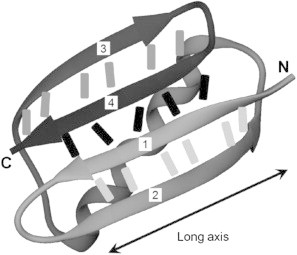
Ribbon cartoon representation of the structure of GB1 (PDB: 1PGA) rendered with VMD (36). Bars between β-strands represent backbone hydrogen bonds between strand pairs. The β-strands are numbered from the N-terminus to the C-terminus.
Figure 2.
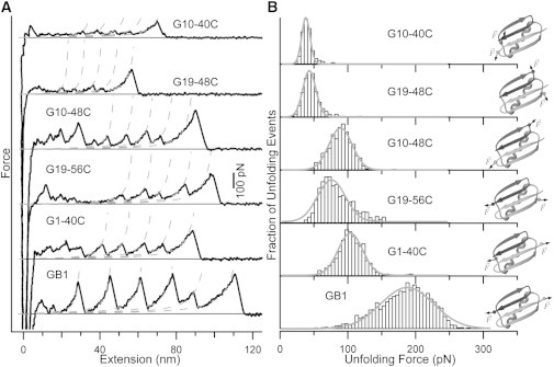
Panel (A): Typical force versus extension traces from single-molecule AFM experiments. Dashed lines are fits generated from an interpolation formula of the worm-like chain model (41). Typical persistence length used is ∼0.4 nm. Panel (B): Normalized frequency histograms of unfolding force with Gaussian fits shown as solid curves to guide the eye. Cartoon illustrations for the protein constructs are shown on the right-hand side. Small spheres represent the Cα atoms of the anchoring residues, whereas the ribbon cartoons are based on the x-ray crystal structure of GB1 (PDB:1PGA) (38).
In a previous study, we developed a protocol for constructing polyproteins with linkages between two precisely controlled amino acid residue positions based on thiol-maleimide coupling chemistry (19). This method is similar to the disulfide bond method developed by Rief and co-workers (16), which has been used to construct polyproteins. We want to emphasize that the loading direction in AFM experiments is defined by the linkages in the polyprotein. In this approach, we need to mutate two native residues in the protein into cysteine residues. Because native structure of GB1 lacks cysteine residues, concerns about formation of unwanted linkages are eliminated. Moreover, these two native residues need to be solvent accessible and sufficiently far apart to avoid intramolecular linkage formation. Based on these criteria, a total of five bicysteine constructs were made (see Fig. 2).
Single-molecule AFM reveals anisotropic response of GB1 to mechanical stress
To investigate the effects of loading direction on the mechanical unfolding of GB1, we carried out constant-velocity single-molecule force spectroscopy experiments on each of the bicysteine GB1 constructs. The force-extension trace obtained from stretching a polyprotein of a construct displays a characteristic sawtooth pattern (e.g., see bottom trace in Fig. 2 A). Each individual force peak in the sawtooth pattern is the result of mechanical unfolding of each individual domain in the polyprotein chain, except for the last force peak, which corresponds to the extension of the unfolded polyprotein and subsequent detachment from either the AFM tip or substrate. Here, we want to emphasize that mechanical unfolding of each domain happens between the engineered cysteine residues. The rising edge of each force peak is well described by the worm-like chain model of polymer elasticity (41). Contour length increments ΔLc calculated from a successive worm-like chain fit to the force peaks agree well with expected values from structural considerations (see Materials and Methods: single-molecule AFM experiment). These two observations taken together suggest the folded protein domains are completely unraveled between the points of attachment in an all-or-none fashion.
Because mechanical unfolding of a protein is stochastic, unfolding force of a protein will fluctuate randomly around a mean value. The unfolding force histograms of the five constructs at 400 nm/s pulling velocity are reported in Fig. 2 B. G1-40C unfolds at a mean force of ∼110 pN making it the mechanically strongest construct of the five pulling geometries we investigated, whereas the mechanically weakest G10-40C construct unfolds at ∼40 pN. We note that even the strongest construct unfolds at significantly lower force than wt GB1, which unfolds at ∼180 pN when it is stretched from its N-C termini (22), suggesting that the pulling direction along the N-C termini remains the most mechanically resistant pulling geometry. From the unfolding force histograms, it is clear that the distribution of unfolding forces also depends strongly on the loading direction. Furthermore, we observe that both the mean and variance of unfolding forces are larger when the pulling vector is close to parallel to the long axis of the β-sheet. This is the case for constructs G1-40C, G19-56C, and G10-48C. On the other hand, both values are smaller when the pulling vector is not aligned with the long axis of the β-sheet as seen in the histograms for constructs G10-40C and G19-48C.
To further characterize the mechanical unfolding of GB1 under different loading geometries, we examined the dependency of the unfolding force on pulling velocity by measuring the force extension relationships under different pulling velocities. Because mechanical unfolding of all constructs happens in an all-or-none fashion, the kinetics of their mechanical unfolding can be modeled as a two-state system with a force-dependent unfolding rate constant. The Bell model (42) characterizes mechanical unfolding kinetics using the unfolding rate constant at zero force α0 and the unfolding distance Δxu, which is the distance between the native state and the mechanical unfolding transition state. These two parameters can be extracted from pulling velocity dependency data (Fig. 3) using a Monte Carlo simulation based on a published protocol (43). From the values tabulated in Table 1, we note that pulling velocity dependency of the unfolding force of G19-48C and G10-48C can be adequately reproduced using the same rate constant α0 as GB1 but with a different unfolding distance Δxu. However, α0 for GB1 fails to reproduce the behaviors of G19-56C and G1-40C. For these constructs, both α0 and Δxu have different values when compared to GB1. According to the values of Δxu, the constructs can be divided into three groups with small (GB1), intermediate (G1-40C, G19-56C, and G10-48C), and large (G19-48C and possibly G10-40C) Δxu values. A smaller Δxu value implies the transition state of mechanical unfolding is highly native-like. Variations in the mean and variance of the unfolding force reflect differences in the underlying mechanical unfolding free energy profiles. The mean unfolding force is determined by the intrinsic unfolding rate constant at zero force and the distance between the native and transition states (Δxu). Because barrier crossing in mechanical unfolding is thermal driven (hence stochastic), the variance/standard deviation of the unfolding forces is governed by the relative magnitude of the unfolding distance between folded and transition states compared to thermal energy (kBT/Δxu). Therefore, differences in unfolding kinetics/mechanism will lead to changes in the mean and variance/standard deviation of the unfolding force distribution. It is reasonable to anticipate that unfolding in mechanical strong (higher mean value of unfolding forces) and weak (lower mean value) directions proceed via different molecular mechanisms. It is of note that visual inspections on the five constructs (Fig. 2) reveal that this shearing geometry is roughly maintained in the cases of G10-48C, G19-56C, and G1-40C; whereas G10-40C and G19-48C are arranged to unfold the protein in a peeling or unzipping fashion.
Figure 3.
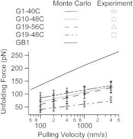
Dependency of unfolding force on the pulling velocity. Kinetic parameters can be estimated from this dependency using Monte Carlo simulations. Experimental unfolding forces for four constructs are represented as symbols with error bars (mean ± SD).
Table 1.
Mechanical unfolding data derived from constant velocity single-molecule AFM experiments and Monte-Carlo simulations
| Construct | Fu (pN) | Δxu (nm) | α0 (s−1) |
|---|---|---|---|
| GB1 | 178 ± 40 | 0.17 | 0.039 |
| G10-40C | 36 ± 9 | – | – |
| G19-48C | 52 ± 16 | 0.58 | 0.039 |
| G10-48C | 92 ± 19 | 0.33 | 0.039 |
| G19-56C | 86 ± 26 | 0.31 | 0.089 |
| G1-40C | 109 ± 23 | 0.38 | 0.0065 |
Fu denotes unfolding force and is reported as mean ± SD (pulling velocity is 400 nm/s). Δxu denotes the unfolding distance, which is the distance between the native state and transition state of mechanical unfolding. α0 denotes the unfolding rate constant at zero force. Pulling velocity dependency for G10-40C was not examined due to low Fu close to the detection limit of our AFM (∼20 pN). Values for GB1 are taken from previously published results (22).
SMD simulation provides insights into the different mechanical unfolding mechanism
To learn about the mechanical unfolding mechanism for each construct, we turned to SMD simulations. Results from SMD studies have been shown to correlate well with single-molecule AFM results (6,7,44). Previous results (24–26,45) have indicated that terminal β-strands 1 and 4 of GB1 (Fig. 1) are in direct contact and form a mechanical clamp motif that resists mechanical stress and protects the protein from unfolding. Previous SMD simulations on GB1 showed that the mechanical unfolding between its N- and C-termini initiates with the separation of the terminal β-strands 1 and 4 (24–26).
We first carried out similar SMD simulations on GB1, which will serve as the benchmark for later comparisons. One representative force-extension plot from such a simulation is shown in Fig. 4 F. The force peak at small extension (<10 Å) is the main event in the graph, which corresponds to the burst of the mechanical clamp. Fig. 4 F also shows a snapshot of GB1 in the simulation trajectory right after the burst. The snapshot shows that terminal β-strands 1 and 4 are separated from each other, whereas the C-terminal hairpin is separated from the α-helix and N-terminal hairpin. In some simulation trajectories (see Fig. 4 D1), there may also be one or two minor force peaks, corresponding to unfolding intermediates not seen in experiments, following the main force peak. All of the notable features of the simulations we have identified agree well with results from previous studies that have been carried out with both implicit and explicit solvent models (24–26). Such close agreements suggest mechanical unfolding pathways identified from SMD simulations are robust and relatively insensitive toward differences between the chosen solvent models.
Figure 4.
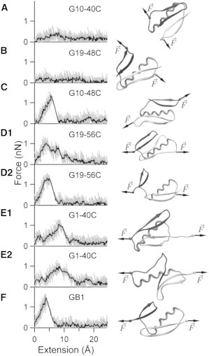
Force versus extension plots from constant velocity SMD simulations. Gray traces are unsmoothed force versus extension traces and black traces are the same traces smoothed with a moving median (box size: 21 points). The common starting structure illustrated in Fig. 1 is not shown. Ribbon cartoon illustrating protein structures are taken just after the main burst event, except for those in (A) and (B), which are taken at an extension of ∼12 Å.
To directly compare between different loading directions and elucidate the effects of loading directions on the mechanical unfolding mechanism, we carried out constant velocity SMD simulations for all of the protein constructs. Typical force versus extension plots are shown in Fig. 4 along with a snapshot from each simulation trajectory. For protein constructs G1-40C and G19-56C, we have included two plots for each because there are two apparent unfolding pathways. Even though unfolding force values obtained from SMD simulations cannot be directly compared to the experimental values due to the vast difference in timescale of the two approaches, we note that our simulations results correctly predict the relative rank of mechanical stabilities. Indeed, our SMD simulations predict that the unfolding force values will decrease from ∼1.5 nN (for GB1) to ∼1.2 nN (for G10-48C, G1-40C, and G19-56C) and finally to nondetectable (for G10-40C and G19-48C), in excellent agreement with experimental results.
Comparing Fig. 4, F and C, it clearly appears that G10-48C unfolds through a pathway very similar to that of GB1. However, force-extension plots for G1-40C and C19-56C are much more complex. In their previous study combining all-atoms and coarse-grained simulations (46), West and colleagues have found that native interactions are more important than nonnative contacts in determining the origin of mechanical strength. Here, we monitor the fractions of native contacts between and within secondary structural elements (namely: N-terminal β-hairpin, C-terminal β-hairpin, and α-helix) for each simulation trajectory. Backbone native contacts (i.e., backbone hydrogen bonds) within structural elements are used as a gauge for the loss of secondary structure; whereas side-chain native contacts between structural elements as well as backbone hydrogen bonds between the β-hairpins (i.e., formed between terminal β-strands 1 and 4) are used to track the loss of tertiary contacts. We have performed this analysis on all of the protein constructs and the results are shown in Fig. 5.
Figure 5.
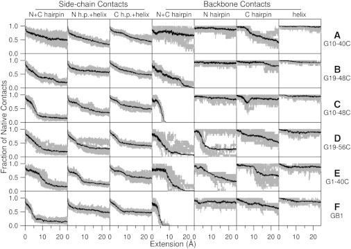
Fraction of native contacts between various structural elements of GB1 derived from SMD simulations. Columns 1 to 7 contain the fraction of intact native contacts between various structural elements during the stretching process: side-chain contacts between N- and C-terminal β-hairpins (N+C hairpin), side-chain contacts between N-terminal β-hairpin and α-helix (N h.p.+helix), side-chain contacts between C-terminal β-hairpin and α-helix (C h.p.+helix), backbone contacts between N- and C-terminal β-hairpins (N+C hairpin), backbone contacts within N-terminal β-hairpin (N hairpin), backbone contacts within C-terminal β-hairpin (C hairpin), and backbone contacts within the α-helix (helix). Gray traces are derived from 10 individual SMD simulations and the black trace is the average of them.
Native contact analysis yields details in the mechanical unfolding mechanism
In the case of GB1, native contact analysis reveals significant loss of native contact between C-terminal β hairpin and α-helix during burst of the mechanical clamp at an extension of ∼5 Å. The burst of the mechanical clamp not only includes rupture of backbone hydrogen bonds between β-hairpins (Fig. 5 F4), but also includes substantial loss of native contacts between the side chains (see Fig. 5, F1, F2, F3). Following the main burst event, there are also some disruptions to the backbone hydrogen bonds within each structural element especially in the C-terminal β-hairpin. The overall picture of the partially unfolded GB1 from our SMD simulations involves rupture of backbone hydrogen bonds between β-hairpins and detachment of the C-terminal β-hairpin from the core. This is in close agreement with previous results (24–26).
Native contact analysis on simulation trajectories for G10-48C (Fig. 5, C1, C2, C3, C4), shows the mechanical unfolding pathway is very similar to that of wild-type GB1, with some slight differences that may account for its lower mechanical stability. Mechanical unfolding of G10-48C is initiated with the concurrent rupture of backbone hydrogen bonds between β-hairpins just like that of GB1. However, both β-hairpins lose native contacts with the α-helix at roughly the same rate, which clearly contrast the asymmetry in the unfolding of GB1. There are some disruptions to the backbone hydrogen bonds in the C-terminal β-hairpin, but these disruptions are quickly diminished following the main burst event. The fact that the C-terminal β-hairpin is not directly subject to mechanical stress for G10-48C, unlike the case for GB1, is reflected in this behavior. When compared to that of G10-48C, mechanical unfolding of GB1 is a much more cooperative process that causes disruption to almost all parts of the protein. Low mechanical stability of G10-48C is also in accordance with a conclusion drawn in our previous study where neighboring β-strands were found to provide critical stabilization (47).
G1-40C and G19-56C are the other two constructs with shearing geometry. SMD simulations on these constructs show two distinct mechanical unfolding pathways for each construct. In the case of G1-40C, both pathways differ with that of GB1 in the sense that the N-terminal β-hairpin is the one detached from the core. In one pathway (Fig. 4 E1), concurrent rupture of hydrogen bonds between β-hairpins is accompanied by sequential rupture of hydrogen bonds within the N-terminal β-hairpin and the main burst event. In the other pathway (Fig. 4 E2), hydrogen bonds within the C-terminal β-hairpin are ruptured concurrently along with sequential rupture of hydrogen bonds between β-hairpins. Main burst events for both pathways occur at a larger extension value than those of GB1 and G10-48C. In the case of G19-56C, one mechanical unfolding pathway (Fig. 4 D2) highly resembles that of GB1.The other pathway (Fig. 4 D1) involves the concurrent rupture of hydrogen bonds within the N-terminal β-hairpin accompanied by sequential rupture of hydrogen bonds between β-hairpins.
G10-40C and G19-48C are the two constructs with peeling geometry. SMD simulations show these constructs unfold via similar pathways that involve the sequential rupture of backbone hydrogen bonds. In the case of G19-48C (Fig. 4 B), the C-terminal β-hairpin detaches from the core like in the case of GB1. However, the peeling geometry causes the backbone hydrogen bonds between β-hairpins to rupture sequentially rather than concurrently. In the case of G10-40C, sequential ruptures of backbone hydrogen bonds happen within the C-terminal β-hairpin (Fig. 4 A). The N-terminal β-hairpin detaches from the core like in the case of G1-40C.
Diverse unfolding mechanisms lead to anisotropic mechanical stability
In this study, we have combined single-molecule AFM and SMD simulations to explore the anisotropic response of a small globular protein to mechanical stress. Single-molecule AFM experiments have revealed marked directional anisotropy in the mechanical response, whereas SMD simulations have clarified its origin based on unfolding mechanisms. To the best of our knowledge, this is the first time that mechanical anisotropy of a protein has been systematically explained in detailed mechanistic terms based on all-atom SMD simulations. Topological differences between shearing (G10-48C) and peeling (G19-48C) geometries have been linked with mechanistic differences between concurrent and sequential ruptures of critical backbone hydrogen bonds. This finding using only one protein is in line with previous findings using two proteins with different geometries (9).
Perhaps the most interesting finding from the SMD simulations is the presence of parallel unfolding pathways. Simulations reveal both G1-40C and G19-56C have two apparently distinct unfolding pathways, whereas G10-48C has only one. However, these three constructs display similar behaviors in our experiments (in term of mean and variance of unfolding force). Because the simulations are carried out on a timescale that is much faster (∼106) compared to experiments, these possible parallel pathways must be met with caution. A strategy involving the redesign of unfolding pathways, which has been used in our previous study (48), offers one method to test these predictions. In such a scenario (e.g., take the case of G19-56C), a disulfide bond (or a bihistidine metal binding site (49)) could be engineered at an appropriate site across β-strands 1 and 2 to stabilize the N-terminal β-hairpin. This would result in the GB1-like unfolding pathway (Fig. 4 D2) to be favored and it could possibly shift the mean unfolding force to a higher value.
Recent work (27) by Graham and Best is also concerned with the role of force on the unfolding pathways of GB1. In their coarse-grained Gō-like model based study, Graham and Best have focused on the switch from an intrinsic unfolding pathway to a novel mechanical unfolding pathway (27). The authors predict a nonlinear relationship between the mean unfolding force and logarithm of the pulling velocity for GB1 and G10-48C type constructs at very low pulling velocity. This phenomenon has not been observed in our experiments, possibly due to the relatively high pulling velocities used. Large differences between chemical and mechanical unfolding rate constants at zero denaturant and zero force (22) suggest that chemical and mechanical unfolding of GB1 follow different unfolding pathways, a result consistent with our recent mechanical ψ-value analysis on the mechanical unfolding of GB1 (50). It would be interesting to observe whether these two alternative pathways do switch at low forces/pulling velocity. To do so, instrumental drift needs to be minimized and force detection limit needs to be improved at the same time.
In our present study, we found that the small globular protein GB1 exhibits clear directional anisotropy to mechanical stress. The mechanically most robust construct is the wild-type GB1 that unfolds at ∼180 pN, whereas the most labile construct is G10-40C that unfolds at ∼40 pN. Differences in unfolding mechanisms have been identified to dictate differences in mechanical stability. Because molecular determinants of mechanical stability are still not completely understood (13), the rational design of mechanical proteins and materials based on them will be undoubtedly aided by detailed characterization of the unfolding pathways and effects of force on such pathways.
Acknowledgments
This work was supported by the Natural Sciences and Engineering Research Council of Canada, Canada Foundation for Innovation and Canada Research Chair program (to H.L.). Y.D.L. is partially supported by an Alexander Graham Bell Canada Graduate Scholarship at the master’s level from the Natural Sciences and Engineering Research Council of Canada.
References
- 1.Vogel V. Mechanotransduction involving multimodular proteins: converting force into biochemical signals. Annu. Rev. Biophys. Biomol. Struct. 2006;35:459–488. doi: 10.1146/annurev.biophys.35.040405.102013. [DOI] [PubMed] [Google Scholar]
- 2.Li H., Cao Y. Protein mechanics: from single molecules to functional biomaterials. Acc. Chem. Res. 2010;43:1331–1341. doi: 10.1021/ar100057a. [DOI] [PubMed] [Google Scholar]
- 3.Rief M., Gautel M., Gaub H.E. Reversible unfolding of individual titin immunoglobulin domains by AFM. Science. 1997;276:1109–1112. doi: 10.1126/science.276.5315.1109. [DOI] [PubMed] [Google Scholar]
- 4.Tskhovrebova L., Trinick J., Simmons R.M. Elasticity and unfolding of single molecules of the giant muscle protein titin. Nature. 1997;387:308–312. doi: 10.1038/387308a0. [DOI] [PubMed] [Google Scholar]
- 5.Kellermayer M.S.Z., Smith S.B., Bustamante C. Folding-unfolding transitions in single titin molecules characterized with laser tweezers. Science. 1997;276:1112–1116. doi: 10.1126/science.276.5315.1112. [DOI] [PubMed] [Google Scholar]
- 6.Lu H., Isralewitz B., Schulten K. Unfolding of titin immunoglobulin domains by steered molecular dynamics simulation. Biophys. J. 1998;75:662–671. doi: 10.1016/S0006-3495(98)77556-3. [DOI] [PMC free article] [PubMed] [Google Scholar]
- 7.Paci E., Karplus M. Unfolding proteins by external forces and temperature: the importance of topology and energetics. Proc. Natl. Acad. Sci. USA. 2000;97:6521–6526. doi: 10.1073/pnas.100124597. [DOI] [PMC free article] [PubMed] [Google Scholar]
- 8.Klimov D.K., Thirumalai D. Native topology determines force-induced unfolding pathways in globular proteins. Proc. Natl. Acad. Sci. USA. 2000;97:7254–7259. doi: 10.1073/pnas.97.13.7254. [DOI] [PMC free article] [PubMed] [Google Scholar]
- 9.Carrion-Vazquez M., Oberhauser A.F., Fernandez J.M. Mechanical design of proteins studied by single-molecule force spectroscopy and protein engineering. Prog. Biophys. Mol. Biol. 2000;74:63–91. doi: 10.1016/s0079-6107(00)00017-1. [DOI] [PubMed] [Google Scholar]
- 10.Ng S.P., Billings K.S., Clarke J. Designing an extracellular matrix protein with enhanced mechanical stability. Proc. Natl. Acad. Sci. USA. 2007;104:9633–9637. doi: 10.1073/pnas.0609901104. [DOI] [PMC free article] [PubMed] [Google Scholar]
- 11.Sadler D.P., Petrik E., Brockwell D.J. Identification of a mechanical rheostat in the hydrophobic core of protein L. J. Mol. Biol. 2009;393:237–248. doi: 10.1016/j.jmb.2009.08.015. [DOI] [PMC free article] [PubMed] [Google Scholar]
- 12.Forman J.R., Clarke J. Mechanical unfolding of proteins: insights into biology, structure and folding. Curr. Opin. Struct. Biol. 2007;17:58–66. doi: 10.1016/j.sbi.2007.01.006. [DOI] [PubMed] [Google Scholar]
- 13.Crampton N., Brockwell D.J. Unravelling the design principles for single protein mechanical strength. Curr. Opin. Struct. Biol. 2010;20:508–517. doi: 10.1016/j.sbi.2010.05.005. [DOI] [PubMed] [Google Scholar]
- 14.Carrion-Vazquez M., Li H.B., Fernandez J.M. The mechanical stability of ubiquitin is linkage dependent. Nat. Struct. Biol. 2003;10:738–743. doi: 10.1038/nsb965. [DOI] [PubMed] [Google Scholar]
- 15.Brockwell D.J., Paci E., Radford S.E. Pulling geometry defines the mechanical resistance of a beta-sheet protein. Nat. Struct. Biol. 2003;10:731–737. doi: 10.1038/nsb968. [DOI] [PubMed] [Google Scholar]
- 16.Dietz H., Berkemeier F., Rief M. Anisotropic deformation response of single protein molecules. Proc. Natl. Acad. Sci. USA. 2006;103:12724–12728. doi: 10.1073/pnas.0602995103. [DOI] [PMC free article] [PubMed] [Google Scholar]
- 17.Yang G.L., Cecconi C., Bustamante C. Solid-state synthesis and mechanical unfolding of polymers of T4 lysozyme. Proc. Natl. Acad. Sci. USA. 2000;97:139–144. doi: 10.1073/pnas.97.1.139. [DOI] [PMC free article] [PubMed] [Google Scholar]
- 18.Dietz H., Bertz M., Rief M. Cysteine engineering of polyproteins for single-molecule force spectroscopy. Nat. Protoc. 2006;1:80–84. doi: 10.1038/nprot.2006.12. [DOI] [PubMed] [Google Scholar]
- 19.Zheng P., Cao Y., Li H.B. Facile method of constructing polyproteins for single-molecule force spectroscopy studies. Langmuir. 2011;27:5713–5718. doi: 10.1021/la200915d. [DOI] [PubMed] [Google Scholar]
- 20.Nome R.A., Zhao J.M., Scherer N.F. Axis-dependent anisotropy in protein unfolding from integrated nonequilibrium single-molecule experiments, analysis, and simulation. Proc. Natl. Acad. Sci. USA. 2007;104:20799–20804. doi: 10.1073/pnas.0701281105. [DOI] [PMC free article] [PubMed] [Google Scholar]
- 21.Lee W., Zeng X., Marszalek P.E. Mechanical anisotropy of ankyrin repeats. Biophys. J. 2012;102:1118–1126. doi: 10.1016/j.bpj.2012.01.046. [DOI] [PMC free article] [PubMed] [Google Scholar]
- 22.Cao Y., Lam C., Li H. Nonmechanical protein can have significant mechanical stability. Angew. Chem. Int. Ed. Engl. 2006;45:642–645. doi: 10.1002/anie.200502623. [DOI] [PubMed] [Google Scholar]
- 23.Cao Y., Li H.B. Polyprotein of GB1 is an ideal artificial elastomeric protein. Nat. Mater. 2007;6:109–114. doi: 10.1038/nmat1825. [DOI] [PubMed] [Google Scholar]
- 24.Li P.C., Huang L., Makarov D.E. Mechanical unfolding of segment-swapped protein G dimer: results from replica exchange molecular dynamics simulations. J. Phys. Chem. B. 2006;110:14469–14474. doi: 10.1021/jp056422i. [DOI] [PubMed] [Google Scholar]
- 25.Glyakina A.V., Balabaev N.K., Galzitskaya O.V. Mechanical unfolding of proteins L and G with constant force: similarities and differences. J. Chem. Phys. 2009;131:045102. doi: 10.1063/1.3183974. [DOI] [PubMed] [Google Scholar]
- 26.Glyakina A.V., Balabaev N.K., Galzitskaya O.V. Multiple unfolding intermediates obtained by molecular dynamic simulations under stretching for immunoglobulin-binding domain of protein G. Open Biochem. J. 2009;3:66–77. doi: 10.2174/1874091X00903010066. [DOI] [PMC free article] [PubMed] [Google Scholar]
- 27.Graham T.G.W., Best R.B. Force-induced change in protein unfolding mechanism: discrete or continuous switch? J. Phys. Chem. B. 2011;115:1546–1561. doi: 10.1021/jp110738m. [DOI] [PubMed] [Google Scholar]
- 28.Fernandez J.M., Li H.B. Force-clamp spectroscopy monitors the folding trajectory of a single protein. Science. 2004;303:1674–1678. doi: 10.1126/science.1092497. [DOI] [PubMed] [Google Scholar]
- 29.Florin E.L., Rief M., Gaub H.E. Sensing specific molecular interactions with the atomic force microscope. Biosens. Bioelectron. 1995;10:895–901. [Google Scholar]
- 30.Brooks B.R., Brooks C.L., 3rd, Karplus M. CHARMM: the biomolecular simulation program. J. Comput. Chem. 2009;30:1545–1614. doi: 10.1002/jcc.21287. [DOI] [PMC free article] [PubMed] [Google Scholar]
- 31.Brooks B.R., Bruccoleri R.E., Karplus M. CHARMM: a program for macromolecular energy, minimization, and dynamics calculations. J. Comput. Chem. 1983;4:187–217. [Google Scholar]
- 32.MacKerell A.D., Bashford D., Karplus M. All-atom empirical potential for molecular modeling and dynamics studies of proteins. J. Phys. Chem. B. 1998;102:3586–3616. doi: 10.1021/jp973084f. [DOI] [PubMed] [Google Scholar]
- 33.Mackerell A.D., Jr., Feig M., Brooks C.L., 3rd Extending the treatment of backbone energetics in protein force fields: limitations of gas-phase quantum mechanics in reproducing protein conformational distributions in molecular dynamics simulations. J. Comput. Chem. 2004;25:1400–1415. doi: 10.1002/jcc.20065. [DOI] [PubMed] [Google Scholar]
- 34.Haberthür U., Caflisch A. FACTS: fast analytical continuum treatment of solvation. J. Comput. Chem. 2008;29:701–715. doi: 10.1002/jcc.20832. [DOI] [PubMed] [Google Scholar]
- 35.Ryckaert J.P., Ciccotti G., Berendsen H.J.C. Numerical-integration of Cartesian equations of motion of a system with constraints: molecular-dynamics of n-alkanes. J. Comput. Phys. 1977;23:327–341. [Google Scholar]
- 36.Humphrey W., Dalke A., Schulten K. VMD: visual molecular dynamics. J. Mol. Graph. 1996;14:33–38. doi: 10.1016/0263-7855(96)00018-5. 27–28. [DOI] [PubMed] [Google Scholar]
- 37.Gronenborn A.M., Filpula D.R., Clore G.M. A novel, highly stable fold of the immunoglobulin binding domain of streptococcal protein G. Science. 1991;253:657–661. doi: 10.1126/science.1871600. [DOI] [PubMed] [Google Scholar]
- 38.Gallagher T., Alexander P., Gilliland G.L. Two crystal structures of the B1 immunoglobulin-binding domain of streptococcal protein G and comparison with NMR. Biochemistry. 1994;33:4721–4729. [PubMed] [Google Scholar]
- 39.Overington J.P. Comparison of three-dimensional structures of homologous proteins. Curr. Opin. Struct. Biol. 1992;2:394–401. [Google Scholar]
- 40.Orengo C. Classification of protein folds. Curr. Opin. Struct. Biol. 1994;4:429–440. [Google Scholar]
- 41.Marko J.F., Siggia E.D. Stretching DNA. Macromolecules. 1995;28:8759–8770. [Google Scholar]
- 42.Bell G.I. Models for the specific adhesion of cells to cells. Science. 1978;200:618–627. doi: 10.1126/science.347575. [DOI] [PubMed] [Google Scholar]
- 43.Carrion-Vazquez M., Oberhauser A.F., Fernandez J.M. Mechanical and chemical unfolding of a single protein: a comparison. Proc. Natl. Acad. Sci. USA. 1999;96:3694–3699. doi: 10.1073/pnas.96.7.3694. [DOI] [PMC free article] [PubMed] [Google Scholar]
- 44.Sotomayor M., Schulten K. Single-molecule experiments in vitro and in silico. Science. 2007;316:1144–1148. doi: 10.1126/science.1137591. [DOI] [PubMed] [Google Scholar]
- 45.Cao Y., Li H.B. Engineered elastomeric proteins with dual elasticity can be controlled by a molecular regulator. Nat. Nanotechnol. 2008;3:512–516. doi: 10.1038/nnano.2008.168. [DOI] [PubMed] [Google Scholar]
- 46.West D.K., Brockwell D.J., Paci E. Mechanical resistance of proteins explained using simple molecular models. Biophys. J. 2006;90:287–297. doi: 10.1529/biophysj.105.071035. [DOI] [PMC free article] [PubMed] [Google Scholar]
- 47.Sharma D., Feng G., Li H. Stabilization provided by neighboring strands is critical for the mechanical stability of proteins. Biophys. J. 2008;95:3935–3942. doi: 10.1529/biophysj.108.134072. [DOI] [PMC free article] [PubMed] [Google Scholar]
- 48.Sharma D., Perisic O., Li H. Single-molecule force spectroscopy reveals a mechanically stable protein fold and the rational tuning of its mechanical stability. Proc. Natl. Acad. Sci. USA. 2007;104:9278–9283. doi: 10.1073/pnas.0700351104. [DOI] [PMC free article] [PubMed] [Google Scholar]
- 49.Cao Y., Yoo T., Li H.B. Single molecule force spectroscopy reveals engineered metal chelation is a general approach to enhance mechanical stability of proteins. Proc. Natl. Acad. Sci. USA. 2008;105:11152–11157. doi: 10.1073/pnas.0803446105. [DOI] [PMC free article] [PubMed] [Google Scholar]
- 50.Shen T., Cao Y., Li H. Engineered bi-histidine metal chelation sites map the structure of the mechanical unfolding transition state of an elastomeric protein domain GB1. Biophys. J. 2012;103:807–816. doi: 10.1016/j.bpj.2012.07.019. [DOI] [PMC free article] [PubMed] [Google Scholar]