Abstract
We present a numerical approach to extract the dispersion mismatch in ultrahigh-resolution Fourier domain optical coherence tomography (OCT) imaging of the retina. The method draws upon an analogy with a Shack-Hartmann wavefront sensor. By exploiting mathematical similarities between the expressions for aberration in optical imaging and dispersion mismatch in spectral / Fourier domain OCT, Shack-Hartmann principles can be extended from the two-dimensional paraxial wavevector space (or the x-y plane in the spatial domain) to the one-dimensional wavenumber space (or the z-axis in the spatial domain). For OCT imaging of the retina, different retinal layers, such as the retinal nerve fiber layer (RNFL), the photoreceptor inner and outer segment junction (IS/OS), or all the retinal layers near the retinal pigment epithelium (RPE) can be used as point source beacons in the axial direction, analogous to point source beacons used in conventional two-dimensional Shack-Hartman wavefront sensors for aberration characterization. Subtleties regarding speckle phenomena in optical imaging, which affect the Shack-Hartmann wavefront sensor used in adaptive optics, also occur analogously in this application. Using this approach and carefully suppressing speckle, the dispersion mismatch in spectral / Fourier domain OCT retinal imaging can be successfully extracted numerically and used for numerical dispersion compensation to generate sharper, ultrahigh-resolution OCT images.
OCIS codes: (170.3880) Medical and biological imaging, (170.4500) Optical coherence tomography, (170.4470) Ophthalmology, (260.2030) Dispersion
1. Introduction
After the development and first demonstration of optical coherence tomography (OCT) imaging of the human retina [1–3], OCT has become a clinical standard in ophthalmic diagnosis and research [4]. Since then, there have been significant efforts in increasing the imaging speed and resolution of OCT. While the axial resolution of standard clinical ophthalmic OCT systems is 5-7 µm, ultrahigh resolution OCT images of the retina with an axial resolution approaching 3 µm or less have been demonstrated using broadband light sources [5–8]. Ultrahigh-resolution imaging is important because it can contribute to better understanding of pathogenesis and enable earlier diagnosis of retinal diseases [9, 10].
For ultrahigh resolution OCT, dispersion mismatch between the sample and reference arms can cause a significant broadening of the axial point spread function [11, 12]. Therefore, to achieve the best possible axial resolution, it is important to compensate for dispersion mismatch accurately. While it is possible to closely match the dispersion of optical components between sample and reference paths and match ocular dispersion by inserting an appropriate length water cell in the OCT reference arm, it is difficult to account for variability in axial eye lengths between different individuals. Therefore, numerical dispersion compensation is typically employed to correct residual dispersion mismatch [7, 8, 13].
Fourier domain OCT is particularly well-suited for numerical dispersion compensation because it provides direct access to the spectral interferogram. However, the exact dispersion mismatch is typically unknown and needs to be found by post processing the OCT data. There are two widely used types of approaches for numerical dispersion compensation in retinal imaging. The first is to use bright specular reflections at the foveal surface [8]. The specular reflection is isolated in depth, shifted to the zero-depth position, and inverse Fourier transformed to calculate the dispersion mismatch. The limitation of this approach is that it requires a dominant specular reflection which is not always available. The second type of approach is to assume a third order polynomial for the dispersion mismatch and vary the polynomial coefficients to maximize an image sharpness metric [7, 13]. The limitation of this approach is that it assumes a specific polynomial order for the dispersion mismatch and/or the resultant coefficients could be stationary at a local maximum rather than the global maximum. Regardless of these limitations, all of these approaches are widely used, and in principle, should all converge to a single answer. Another recently reported approach, different from the two references above, utilizes the cross-correlation of sub-bandwidth reconstructions [14].
Fourier domain OCT and holography are closely related in that they are both coherent interferometric techniques that utilize both intensity and phase information, although the implementations of the two techniques are considerably different [15]. On the other hand, the Shack-Hartmann wavefront sensor is also related to holography in that it is capable of detecting the sample wavefront. Therefore, there are mathematical similarities between Fourier domain OCT and Shack-Hartmann wavefront sensing which may allow the application of similar analytical tools between the two techniques.
In this paper, we present a numerical approach to extract the dispersion mismatch in ultrahigh-resolution spectral / Fourier domain OCT retinal imaging using a Shack-Hartmann wavefront sensor analogy. It is demonstrated that by using this approach and carefully suppressing speckle, the dispersion mismatch in spectral / Fourier domain OCT can be successfully extracted numerically, which can then be used for numerical dispersion compensation to generate sharper ultrahigh-resolution OCT images.
2. Theory and simulation
2.1 Dispersion mismatch in spectral / Fourier domain OCT
In OCT, the spectral interferogram detected by the spectrometer as a function of wavenumber can be expressed as [4, 16–18]:
| (1) |
where , , , , , and are the detector responsivity, optical power spectrum of the light source, power reflectivity of the reference arm, magnitude of the sample field reflectivity, phase of the sample field reflectivity, and dispersion mismatch between the sample and reference arms, respectively. It is important to note that in retinal imaging is commonly approximated to be depth-independent, and therefore is a common term for signals at all depths.
2.2 Aberration in optical imaging
A paraxial plane wave that travels through an optical element with small aberration can be expressed as:
| (2) |
where , and is the wavenumber, x component and y component of the propagation vector, respectively.
To develop an explicit analogy between aberration in optical imaging and dispersion mismatch in Fourier domain OCT, an arbitrary superposition of aberrated planar wavefronts can be interfered with an ideal reference plane wave as in holography:
| (3) |
where is the weight of superposition for the planar waves. The interference term of Eq. (3) can be calculated as:
| (4) |
The mathematical similarities between Eqs. (1) and (4) are now apparent where Eq. (4) is simply a two-dimensional extension of Eq. (1). This implies dispersion mismatch in spectral / Fourier domain OCT and aberration in optical imaging are mathematically analogous.
2.3 Finding dispersion mismatch using Shack-Hartmann wavefront sensor analogy
In optical imaging, a Shack-Hartmann wavefront sensor can be used to find the wavefront distortion induced by an aberration term . The Shack-Hartmann typically contains a lenslet array which divides the input wave into multiple subapertures. The local slope of the wavefront at the center of each of the lenslets can be found by the following equations [19]:
| (5) |
| (6) |
where is the focal length of the lenslets, and and are the deviations of the focal spots in the x and y directions in relative to the center of the lenslet. These discrete local slopes can be used to reconstruct the input wavefront using integration, characterizing the aberration introduced by the optical element. In imaging the eye using adaptive optics, the optical element is the eye itself, and the aberration of the eye can be defined as the deviation of the exiting wavefront after the cornea from an ideal planar wavefront that is assumed to be generated by an ideal optics of the eye with a point source on the retina.
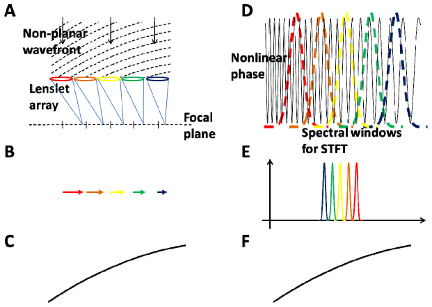
A Shack-Hartmann wavefront sensor can be considered as a local wavefront sampling device. Therefore, utilizing the mathematical analogy developed in the previous sections, it should be possible to perform local phase slope sampling on the spectral / Fourier domain OCT interferogram in order to extract the dispersion mismatch between sample and reference arms. In order to extract dispersion mismatch in spectral / Fourier domain OCT, the lenslet array can be replaced with windowing the interferogram with narrow windows centered at different wavenumbers in the wavenumber space followed by Fourier transformation, which is analogous to the lenslets forming images at the focal plane in a Shack-Hartmann wavefront sensor. In a manner analogous to the way that the lenslets in the Shack-Hartmann wavefront sensor provide local slopes of the incoming wavefront, multiple narrow windows at different center wavenumbers provide local slopes of the phase of the spectral interferogram. Therefore, the dispersion mismatch can be calculated by integrating the phase slope in the wavenumber space in spectral / Fourier domain OCT, just as the wavefront can be calculated by integrating the wavefront slope in the x-y space in Shack-Hartmann wavefront sensing. This analogy is illustrated in Fig. 1 using an example of parabolic wavefront and phase.
Fig. 1.
Finding dispersion mismatch using a Shack-Hartmann wavefront sensor analogy. (A) A lenslet array samples a spatially non-planar parabolic wavefront. (B) The positions of the focused spots on the focal plane are proportional to the local slopes of the wavefront. (C) The wavefront can be reconstructed by integrating the local slope in space. (D) Using multiple spectral windows for STFT, a nonlinear parabolic phase corresponding to a dispersion mismatch can be sampled in wavenumber. (E) The position of the Fourier transform for a given window is proportional to local slope of nonlinear phase. (F) The nonlinear phase can be reconstructed by integrating the local slope in wavenumber. STFT: short-time Fourier transform.
2.4 Simulation
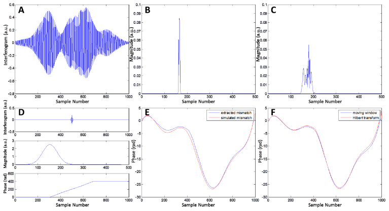
In order to demonstrate that the dispersion mismatch in spectral / Fourier domain OCT can be found using the analogy described above, a numerical simulation was performed to extract a known amount of dispersion mismatch introduced between the sample and reference arms. The spectral interferogram from three scatterers at slightly different depths and its Fourier transform are shown in Figs. 2(a) and 2(b). When a dispersion mismatch added, the A-scan becomes distorted as shown in Fig. 2(c). Figure 2(d) shows an example of the effect of short-time Fourier transform using a narrow window centered at a particular wavenumber. The first panel of Fig. 2(d) shows the effect of windowing on the spectral interferogram. The second panel shows the Fourier transform of the windowed interferogram. Since the window is narrow, it appears as a point or single scatterer, which is analogous to the Shack-Hartmann wavefront sensor, where it is conventionally assumed that the wavefront emerges from a point source. It should also be noted that beyond a certain threshold where it starts to appear as a point scatterer, reducing the window size further does not affect the results significantly. The third panel shows the unwrapped phase of the Hilbert transform of the windowed interferogram shown in the first panel. Note that the location of the peak of the A-scan in the second panel can be defined as the instantaneous slope of this unwrapped phase at the center of the window. This results in a more accurate, sub-pixel location of the peak because of the discrete samples. By sliding the center wavenumber of the window over the entire wavenumber range and integrating the resultant slope in wavenumber, the dispersion mismatch can be extracted as shown in Fig. 2(e). Note that there is a slight difference between the simulated dispersion mismatch and dispersion mismatch extracted by the algorithm because there is more than one scatterer in the A-scan.
Fig. 2.
Simulation for extracting the dispersion mismatch using Shack-Hartmann wavefront sensor analogy. (A) A spectral interferogram with three scatterers and a Gaussian light source. (B) The Fourier transform of (A) without any dispersion mismatch. (C) The Fourier transform of the interferogram with an arbitrary simulated dispersion mismatch introduced. (D) An example of the short-time Fourier transform for a given window location. (E) A comparison of the simulated and extracted dispersion mismatches. (F) A comparison of the extracted dispersion mismatch calculated with short-time Fourier transform with a sweeping window and that calculated with Hilbert transforming the entire spectral interferogram.
This result is expected for a single scatterer, but for multiple scatterers, it is not obvious whether this approach remains valid. However, as will be shown in the next section, by carefully considering the analogy between this approach and the Shack-Hartmann wavefront sensor, it is possible to infer that this approach should still be valid for multiple scatterers when speckles are appropriately managed.
Figure 2(f) shows that the entire operation of the sliding window short-time Fourier transform can be simply replaced by Hilbert transformation of the entire interferogram without short-time Fourier transformation. Since the operation described above essentially calculates the integral of the instantaneous slope of the phase, while the Hilbert transform of the entire interferogram calculates the phase, they are equivalent. This fact is highly advantageous computationally because of the high computational cost of short-time Fourier transformation with multiple windows. Therefore, short-time Fourier transformation is used here only for developing the analogy between this approach and the Shack-Hartmann. Note that there is a slight difference between the two curves in Fig. 2(f) because the instantaneous slope was calculated using a finite window width with a finite wavenumber interval.
2.5 Effect of speckle
For A-scans with a single scatterer or specular reflections, variations of the approach outlined previously have already been widely used for finding the dispersion mismatch in Fourier domain OCT [8, 20]. However, the validity of this approach for A-scans with multiple scatterers is not obvious without the analogy developed previously.
In Shack-Hartmann wavefront sensing for imaging the eye, it is typically assumed that the wavefront coming from the beacon on the retina is a point source. Although this is true in terms of the resolution of the small lenses in the lenslet array, there are still multiple scatterers that act as the beacon on the retina. Therefore, speckle can be a problem for accurate aberration characterization with a typical Shack-Hartmann wavefront sensor [21]. Similarly, in finding the dispersion mismatch in spectral / Fourier domain OCT using the analogy developed here, speckle can be a severe problem when there are multiple scatterers in a single A-scan. The effect of speckle on the approach described here is shown in Fig. 3 . Figure 3(a) shows a spectral interferogram with three scatterers as in Fig. 2, but with the relative locations shifted to cause severe constructive and destructive interferences. This constructive and destructive interference results in speckle patterns when narrow windows are used for short-time Fourier transform. Note that an analogous problem can occur in Shack-Hartmann wavefront sensors. Figure 3(b) shows the dispersion mismatch extracted with the approach described above. Note that an abrupt jump occurs where there is destructive interference. These abrupt jumps can cause a splitting of the OCT point spread function when the dispersion mismatch is used for numerical dispersion compensation.
Fig. 3.
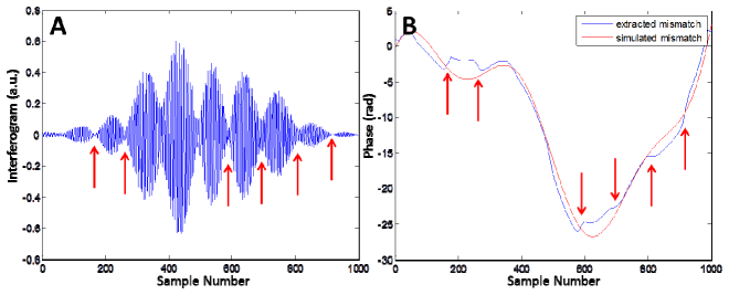
(A) A spectral interferogram with three scatterers. The wavenumbers where destructive interference occurs are indicated with red arrows. (B) A comparison of the extracted dispersion mismatch and the simulated dispersion mismatch. The red arrows indicate the same wavenumbers as in (A). Note that the abrupt changes in the extracted dispersion mismatch occur at the wavenumbers indicated with the arrows.
One obvious way of suppressing speckle and other noise for the Shack-Hartmann wavefront sensor is to average multiple images assuming small sample movement between acquisitions [22]. In typical OCT imaging, multiple A-scans are acquired while the galvanometer is scanning. Therefore, in order to suppress speckle for extracting the dispersion mismatch in spectral / Fourier domain OCT, multiple neighboring A-scans with different speckle patterns can be averaged. Note that averaging is not performed on the interferograms, but on the extracted dispersion mismatches from the A-scans. The effect of speckle suppression by averaging the dispersion mismatch will be shown in the results section.
3. Methodology
3.1 Ultrahigh-resolution spectral / Fourier domain OCT system
Two different OCT systems were used in these experiments. A schematic of the OCT systems used is shown in Fig. 4 . For the first system, a commercial broadband superluminescent diode (SLD) light source (Exalos) and a line scan camera (Basler Sprint spL4096-140 km) were used to develop an ultrahigh-resolution spectral domain OCT system at 825 nm with an imaging speed of 70,000 A-scans per second. The full width at half maximum (FWHM) bandwidth of the broadband light source was 161 nm. The spectrometer had a collimating lens with an effective focal length of 76 mm, a 1200 lines/mm transmission holographic grating, and a 160 mm scan lens. The line scan camera had 10 µm square pixels in two rows and was 4096 pixels wide. The camera was read at a 70 kHz line rate using the full 4096 pixels with a 13.1 µs exposure time. The total imaging range was 3.1 mm in tissue with a measured axial resolution of 2.9 μm in tissue after spectral shaping. Using a 70/30 fiber coupler, the power of the OCT beam at the cornea was 750 µW, consistent with American National Standards Institute (ANSI) standards safe exposure limits, and gave a sensitivity of 97 dB. The imaging interface had galvanometer scanners with 5 mm mirrors (Cambridge Technology 6215H), an 80 mm scan lens, and a compound 30 mm effective focal length ocular lens, resulting in a beam diameter of 1.8 mm incident on the cornea. The theoretical retinal spot size calculated with ZEMAX and a standard eye model was ~20 µm.
Fig. 4.
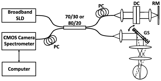
Schematic of the spectral / Fourier domain ultrahigh-resolution OCT systems. PC: polarization controller, DC: dispersion compensation glass, RM: reference mirror, GS: galvanometer scanner pair, DG: diffraction grating, SLD: superluminescent diode, CMOS: line scan camera. Fiber couplers of 70/30 and 80/20 were used for the first and second systems, respectively.
For the second system, a different broadband SLD (Superlum) centered at 860 nm with a FWHM bandwidth of 137 nm was used in order to increase the imaging speed as well as the system efficiency. For this configuration, the camera was read at a line rate of 91 kHz using the center 3072 pixels with an exposure time of 9.8 µs. An 80/20 fiber coupler used for this configuration to limit the incident power of the OCT beam to 750 µW. Otherwise, the second system was similar to the first. The second system was designed with emphasis on optimizing efficiency and sensitivity, and sensitivity was improved to 98 dB despite the faster imaging speed. The total imaging range remained the same at 3.1 mm in tissue with a measured axial resolution of 3.2 μm in tissue after spectral shaping.
3.2 System calibration and data processing
In order to achieve best possible resolution allowed by the spectrometer and light source at all depths, it is critical to decouple the dispersion mismatch from wavelength-to-camera pixel mapping during spectrometer recalibration. For that purpose, the spectrometer was calibrated using an approach similar to that described in reference [20]. Interferometric fringes were recorded by placing a mirror at two different delay positions in the sample arm. The two interferometric fringes were Hilbert transformed to generate phase curves as a function of pixel number. By subtracting the two phase curves, the phase as a function of pixel number, but without dispersion mismatch, was generated. The new sampling positions to linearize the interferometric fringe in wavenumber could be generated by dividing the total phase range by the final number of samples and interpolating the sample positions corresponding to the phase values with uniform intervals. It should be noted that the approach in reference [20] can also be used for finding the dispersion mismatch in the OCT system. However, unlike our approach discussed here, it is not intended for sample-dependent dispersion mismatch because it requires a calibration mirror.
For all data acquired in this study, the spectrometer output was processed by cubic spline interpolation to linearize the interference signal in wavenumber. The recalibrated interferometric signals were Fourier transformed after numerically compensating for the dispersion mismatch. Zero padding was sometimes performed before Fourier transformation in order to improve layer visualization.
4. Results and discussion
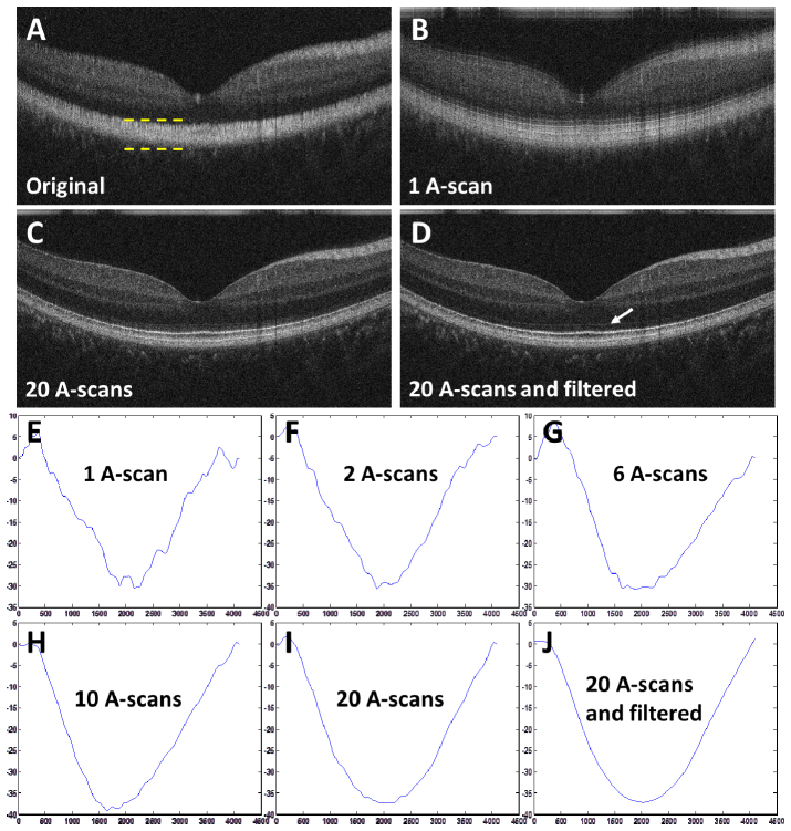
The approach to extract the dispersion mismatch described above was applied to spectral / Fourier domain OCT images. In OCT images of the retina, there are always multiple scatterers in a given A-scan, and the effect of speckle should be considered carefully in order to apply this method successfully. The first ultrahigh resolution OCT system was used to acquire the B-scan with 2048 A-scans as shown in Fig. 5(a) . No water cell was used in the reference arm in order to intentionally demonstrate that the approach is capable of extracting a relatively large dispersion mismatch. The method was applied to the A-scans near the center of the fovea. Before implementing the method, the A-scans were zeroed everywhere except at the bright layers near the retinal pigment epithelium (RPE), and inverse Fourier transformed to increase the signal-to-noise ratio of the spectral interferograms and remove signals from undesired layers. The depth range where the A-scan was used is approximately indicated by the yellow dotted lines in Fig. 5(a). The resulting spectral interferograms were used as the starting point for the approach.
Fig. 5.
(A) An original OCT B-scan image of a normal human retina. (B, C, D) OCT B-scans numerically dispersion compensated with the mismatches shown in (E, I, J). The white arrow in (D) indicates the external limiting membrane (ELM). (E-I) Dispersion mismatches extracted from different numbers of A-scans. (J) was obtained by filtering (I) with a Savatzky-Golay filter. For (E-J), the y-axis indicates phase in radian and the x-axis sample number.
Figure 5(e) shows the extracted dispersion mismatch from a single A-scan. Note that there are several abrupt jumps in the extracted dispersion mismatch due to noise and speckle, which can be understood in terms of the short-time Fourier transforms described earlier. When this mismatch is used for numerical dispersion compensation, the OCT point spread function splits, as can be seen in Fig. 5(b). Note that the image became sharper compared to Fig. 5(a), although image feature appear split multiple times in depth. This is not surprising considering the effect shown earlier in Fig. 3(b). Figures 5(f)-5(i) show the averages of dispersion mismatches extracted from different numbers of A-scans in order to reduce speckle. The extracted dispersion mismatch is averaged according to the number of A-scans indicated. Note that as larger numbers of A-scans are used for averaging, the abrupt jumps in the extracted phase are reduced. Figure 5(j) was obtained by filtering Fig. 5(i) with a Savitzky-Golay filter (polynomial order: 1, window size: 401, number of samples per A-scan: 4096) in order to further suppress the effect of speckle. Figures 5(c) and 5(d) show the numerically dispersion compensated B-scans using the extracted dispersion mismatches shown in Figs. 5(i) and 5(j), respectively. Both Figs. 5(c) and 5(d) became noticeably sharper than the original image. However, Fig. 5(d) resulted in a cleaner image as can be seen by examining the area below the external limiting membrane (ELM). It is important to emphasize that the extracted dispersion mismatches are averaged for speckle reduction, while the spectral interferograms are not averaged before extracting the mismatch. It should also be noted that the purpose of averaging is not to increase signal-to-noise ratio, but to reduce the effects of speckle.
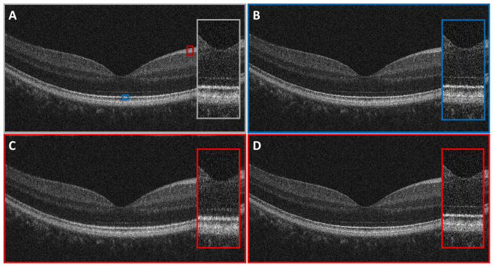
In practice, a water cell is typically used in the reference arm for retinal imaging in order to match dispersion from the vitreous of the eye. Therefore, it is important to test whether this approach can be also used to find a smaller amount of dispersion mismatch. Figure 6(a) is an OCT B-scan image of a normal human retina consisting of 2048 A-scans, acquired with the first ultrahigh resolution system, but with a water cell inserted in the reference arm to approximately match dispersion. Figure 6(b) shows a B-scan numerically dispersion compensated with the dispersion mismatch extracted from a single A-scan near the position indicated by the blue box in Fig. 6(a). Only the inner segment / outer segment junction (IS/OS) was used for extracting the dispersion mismatch. Averaging multiple A-scans did not help in this case because IS/OS acted as a good single scatterer with minimal speckle. Figure 6(c) shows a B-scan numerically dispersion compensated with the mismatch extracted from a single A-scan near the position indicated by the red box in Fig. 6(a). In this case, the entire nerve fiber layer (NFL) was used to extract dispersion mismatch. Because the NFL is thick, there are multiple scatterers in a given A-scan. Therefore, the extracted dispersion mismatch has artifacts due to speckle. Figure 6(d) shows a numerically dispersion compensated image with an averaged dispersion mismatch extracted from 20 A-scans near the position indicated by the same red box in Fig. 6(a). The extracted dispersion mismatch was filtered with a Savatzky-Golay filter (polynomial order: 1, window size: 401, number of samples per A-scan: 3072) before it was used for numerical dispersion compensation. As can be seen, averaging and filtering the extracted phase reduces speckle and achieves more accurate extraction of the dispersion mismatch. This result demonstrates that this approach can be applied to diffuse multiple scatterers as long as the speckle is appropriately managed.
Fig. 6.
(A) An original OCT B-scan image of a normal human retina. Dispersion was approximately matched with a water cell in the OCT reference arm. (B) An OCT B-scan numerically dispersion compensated with the dispersion mismatch extracted from a single A-scan near the position indicated by the blue box in (A). Only the IS/OS was used for dispersion mismatch extraction. (C) An OCT B-scan numerically dispersion compensated with the dispersion mismatch extracted from a single A-scan near the position indicated by the red box in (A). The entire NFL was used for dispersion mismatch extraction. (D) The dispersion mismatch was extracted from 20 A-scans near the position indicated by the red box in (A) and averaged and filtered to reduce speckle.
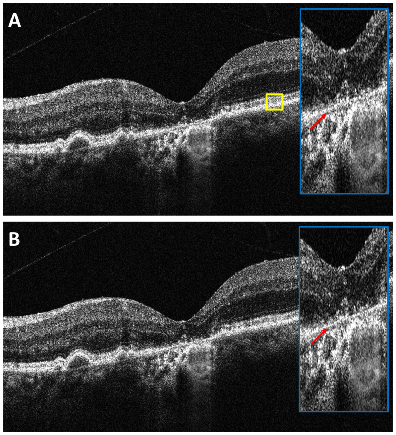
Finally, the approach was applied to images with retinal pathology. Figure 7 shows an OCT retinal image acquired from a patient with dry age-related macular degeneration (AMD) obtained with the second ultrahigh resolution OCT system used at the New England Eye Center. The B-scan image consisted of 16,000 A-scans over 6 mm. A water cell was used in the reference arm for approximate dispersion matching. For this scan pattern, 200 A-scans near the yellow square in Fig. 7(a) were used to extract the dispersion mismatch. Because of the pathology, it was not possible to separate the IS/OS and the retinal pigment epithelium (RPE), and the entire diffuse bright band near the RPE was used, as indicated by the yellow box. Therefore, a relatively large number of A-scans were required to extract the dispersion mismatch. Another reason that a larger number of A-scans were required is that the scan pattern was very dense and the relative difference between neighboring A-scans was proportionally smaller in terms of speckle. Figure 7(b) is a B-scan that is numerically dispersion compensated with the extracted dispersion mismatch averaged over 200 A-scans and filtered with a Savatzky-Golay filter. As can be seen from the zoomed views of Figs. 7(a) and 7(b), the image became sharper using numerical dispersion compensation. The effect of dispersion compensation can be seen by examining the thickness of Bruch’s membrane near the center of the fovea as indicated by arrows.
Fig. 7.
(A) An original OCT B-scan image of a patient with dry AMD. Dispersion was approximately matcched with a water cell inserted in the OCT reference arm. (B) An OCT B-scan numerically dispersion compensated with the averaged and filtered mismatch extracted from 200 A-scan near the position indicated by the yellow box in (A).
There is a very recently published approach that uses the cross-correlation of sub-bandwidth images to characterize and compensate for dispersion as well as sample axial motion artifacts [14]. Although this approach is more closely related to the approach reported here than other approaches mentioned in the introduction in that it uses short-time Fourier transforms, there are still important differences. The approach described in this manuscript does not use cross-correlation of images which can be time consuming especially if it is necessary to achieve sub-pixel accuracy. We also demonstrated that short-time Fourier transforms at multiple wavenumbers can be replaced by single Hilbert transformation, which dramatically reduces computational time. Finally this manuscipt demonstrate that speckle in short-time Fourier transforms can pose additional challenges and proposed an approach to reduce its effects and obtain high quality dispersion compensation.
5. Conclusion
Using a mathematical analogy between the Shack-Hartmann wavefront sensor and Fourier domain OCT, we present an approach to extract the dispersion mismatch between the sample and reference in spectral / Fourier domain OCT. By carefully considering the effect of speckle, which is a common phenomenon occurring in both wavefront sensing and dispersion measurement, the dispersion mismatch was successfully extracted in A-scans with diffuse multiple scatterers as well as a single scatterer. In principle, different approaches for dispersion compensation, including the approach described in this manuscript should converge to a single equivalent solution, which should enable effective compensation of dispersion mismatch. However, the approach described here attempts to extract the dispersion mismatch in a more physically intuitive way, rather than optimizing a metric function. Although this manuscript applies the Shack-Hartmann wavefront sensor analogy to OCT dispersion measurement and compensation, the mathematical analogy also suggests analogs in other applications. For example, it may be possible to extend the approach introduced here to two-dimensions and apply it for characterizing and numerically compensating optical aberration in holography or OCT.
Acknowledgments
This work was supported in part by the National Institutes of Health ( NIH R01-EY011289-26, R01-EY013516-09, 5R01-EY013178-12, R01-EY018184-05, R01-EY019029-04, R01-CA075289-15, R01-NS057476-05, R01-HL095717-03), Air Force Office of Scientific Research (AFOSR FA9550-10-1-0551 and FA9550-10-1-0063) and Samsung Scholarship. The authors thank Ahmad Alwassia and Jason Zhang at New England Eye Center for their help with acquiring patient images. Dr. Bernhard Baumann was visiting from the Center for Medical Physics and Biomedical Engineering, Medical University of Vienna, Austria.
References and links
- 1.Huang D., Swanson E. A., Lin C. P., Schuman J. S., Stinson W. G., Chang W., Hee M. R., Flotte T., Gregory K., Puliafito C. A., Fujimoto J. G., “Optical Coherence Tomography,” Science 254(5035), 1178–1181 (1991). 10.1126/science.1957169 [DOI] [PMC free article] [PubMed] [Google Scholar]
- 2.Swanson E. A., Izatt J. A., Hee M. R., Huang D., Lin C. P., Schuman J. S., Puliafito C. A., Fujimoto J. G., “In vivo retinal imaging by optical coherence tomography,” Opt. Lett. 18(21), 1864–1866 (1993). 10.1364/OL.18.001864 [DOI] [PubMed] [Google Scholar]
- 3.Izatt J. A., Hee M. R., Huang D., Fujimoto J. G., Swanson E. A., Lin C. P., Shuman J. S., Puliafito C. A., “Ophthalmic diagnostics using optical coherence tomography, Proceedings of Ophthalmic Technologies III,” (Spie - Int Soc Opt. Eng. 1877, 136–143 (1993). [Google Scholar]
- 4.W. Drexler and J. G. Fujimoto, Optical coherence tomography: technology and applications (Springer-Verlag, 2008). [Google Scholar]
- 5.Drexler W., Morgner U., Ghanta R. K., Kärtner F. X., Schuman J. S., Fujimoto J. G., “Ultrahigh-resolution ophthalmic optical coherence tomography,” Nat. Med. 7(4), 502–507 (2001). 10.1038/86589 [DOI] [PMC free article] [PubMed] [Google Scholar]
- 6.Leitgeb R. A., Drexler W., Unterhuber A., Hermann B., Bajraszewski T., Le T., Stingl A., Fercher A. F., “Ultrahigh resolution Fourier domain optical coherence tomography,” Opt. Express 12(10), 2156–2165 (2004). 10.1364/OPEX.12.002156 [DOI] [PubMed] [Google Scholar]
- 7.Wojtkowski M., Srinivasan V. J., Ko T. H., Fujimoto J. G., Kowalczyk A., Duker J. S., “Ultrahigh-resolution, high-speed, Fourier domain optical coherence tomography and methods for dispersion compensation,” Opt. Express 12(11), 2404–2422 (2004). 10.1364/OPEX.12.002404 [DOI] [PubMed] [Google Scholar]
- 8.Cense B., Nassif N., Chen T. C., Pierce M. C., Yun S. H., Park B. H., Bouma B., Tearney G., de Boer J. F., “Ultrahigh-resolution high-speed retinal imaging using spectral-domain optical coherence tomography,” Opt. Express 12(11), 2435–2447 (2004). 10.1364/OPEX.12.002435 [DOI] [PubMed] [Google Scholar]
- 9.Drexler W., Sattmann H., Hermann B., Ko T. H., Stur M., Unterhuber A., Scholda C., Findl O., Wirtitsch M., Fujimoto J. G., Fercher A. F., “Enhanced visualization of macular pathology with the use of ultrahigh-resolution optical coherence tomography,” Arch. Ophthalmol. 121(5), 695–706 (2003). 10.1001/archopht.121.5.695 [DOI] [PubMed] [Google Scholar]
- 10.Ko T. H., Fujimoto J. G., Schuman J. S., Paunescu L. A., Kowalevicz A. M., Hartl I., Drexler W., Wollstein G., Ishikawa H., Duker J. S., “Comparison of ultrahigh- and standard-resolution optical coherence tomography for imaging macular pathology,” Ophthalmology 112(11), 1922, –e1–e15. (2005). 10.1016/j.ophtha.2005.05.027 [DOI] [PMC free article] [PubMed] [Google Scholar]
- 11.Drexler W., Morgner U., Kärtner F. X., Pitris C., Boppart S. A., Li X. D., Ippen E. P., Fujimoto J. G., “In vivo ultrahigh-resolution optical coherence tomography,” Opt. Lett. 24(17), 1221–1223 (1999). 10.1364/OL.24.001221 [DOI] [PubMed] [Google Scholar]
- 12.Hitzenberger C. K., Baumgartner A., Drexler W., Fercher A. F., “Dispersion effects in partial coherence interferometry: implications for intraocular ranging,” J. Biomed. Opt. 4(1), 144–151 (1999). 10.1117/1.429900 [DOI] [PubMed] [Google Scholar]
- 13.Yasuno Y., Hong Y. J., Makita S., Yamanari M., Akiba M., Miura M., Yatagai T., “In vivo high-contrast imaging of deep posterior eye by 1-microm swept source optical coherence tomography and scattering optical coherence angiography,” Opt. Express 15(10), 6121–6139 (2007). 10.1364/OE.15.006121 [DOI] [PubMed] [Google Scholar]
- 14.Hillmann D., Bonin T., Lührs C., Franke G., Hagen-Eggert M., Koch P., Hüttmann G., “Common approach for compensation of axial motion artifacts in swept-source OCT and dispersion in Fourier-domain OCT,” Opt. Express 20(6), 6761–6776 (2012). 10.1364/OE.20.006761 [DOI] [PubMed] [Google Scholar]
- 15.Schmitt J. M., Xiang S. H., Yung K. M., “Speckle in optical coherence tomography,” J. Biomed. Opt. 4(1), 95–105 (1999). 10.1117/1.429925 [DOI] [PubMed] [Google Scholar]
- 16.Wojtkowski M., Leitgeb R., Kowalczyk A., Bajraszewski T., Fercher A. F., “In vivo human retinal imaging by Fourier domain optical coherence tomography,” J. Biomed. Opt. 7(3), 457–463 (2002). 10.1117/1.1482379 [DOI] [PubMed] [Google Scholar]
- 17.Leitgeb R., Hitzenberger C. K., Fercher A. F., “Performance of Fourier domain vs. time domain optical coherence tomography,” Opt. Express 11(8), 889–894 (2003). 10.1364/OE.11.000889 [DOI] [PubMed] [Google Scholar]
- 18.Choma M. A., Sarunic M. V., Yang C. H., Izatt J. A., “Sensitivity advantage of swept source and Fourier domain optical coherence tomography,” Opt. Express 11(18), 2183–2189 (2003). 10.1364/OE.11.002183 [DOI] [PubMed] [Google Scholar]
- 19.Liang J. Z., Grimm B., Goelz S., Bille J. F., “Objective measurement of wave aberrations of the human eye with the use of a hartmann-shack wave-front sensor,” J. Opt. Soc. Am. A 11(7), 1949–1957 (1994). 10.1364/JOSAA.11.001949 [DOI] [PubMed] [Google Scholar]
- 20.Makita S., Fabritius T., Yasuno Y., “Full-range, high-speed, high-resolution 1 microm spectral-domain optical coherence tomography using BM-scan for volumetric imaging of the human posterior eye,” Opt. Express 16(12), 8406–8420 (2008). 10.1364/OE.16.008406 [DOI] [PubMed] [Google Scholar]
- 21.Hofer H., Artal P., Singer B., Aragón J. L., Williams D. R., “Dynamics of the eye’s wave aberration,” J. Opt. Soc. Am. A 18(3), 497–506 (2001). 10.1364/JOSAA.18.000497 [DOI] [PubMed] [Google Scholar]
- 22.J. W. Goodman, Speckle phenomena in optics: theory and applications (Roberts & Company, 2007). [Google Scholar]


