

Abstract
Activation of hemostatic pathways by blood-contacting materials remains a major hurdle in the development of clinically durable artificial organs and implantable devices. We postulate that surface-induced thrombosis may be attenuated by the reconstitution onto blood contacting surfaces of bioactive enzymes that regulate the production of thrombin, a central mediator of both clotting and platelet activation cascades. Thrombomodulin (TM), a transmembrane protein expressed by endothelial cells, is an established negative regulator of thrombin generation in the circulatory system. Traditional techniques to covalently immobilize enzymes on solid supports may modify residues contained within or near the catalytic site, thus reducing the bioactivity of surface enzyme assemblies. In this report, we present a molecular engineering and bioorthogonal chemistry approach to site-specifically immobilize a biologically active recombinant human TM fragment onto the luminal surface of small diameter prosthetic vascular grafts. Bioactivity and biostability of TM modified grafts is confirmed in vitro and the capacity of modified grafts to reduce platelet activation is demonstrated using a non-human primate model. These studies indicate that molecularly engineered interfaces that display TM actively limit surface-induced thrombus formation.
Keywords: Biomedical applications, blood compatibility, thrombosis, vascular graft, Staudinger Ligation
1. Introduction
The molecular engineering of biologically active surface assemblies that control host reactions at tissue-material interfaces may be an important step in the development of clinically durable artificial organs and implantable devices.[1, 2] In this regard, pathological thrombus formation on materials in direct contact with blood has precluded development of a clinically durable small-diameter (< 5 mm inner diameter) arterial prosthesis critical to the fields of cardiac, vascular, and plastic surgery, and has necessitated adjunctive antithrombotic therapies that increase bleeding risk and healthcare costs for numerous cardiovascular procedures.[3, 4] The onset and amplification of thrombogenesis on blood-contacting materials involves concomitant activation of platelets and elaboration of the coagulation cascade to generate thrombin and fibrin, culminating in hemostatic plug formation.[5] Thrombin serves as a central initiator, amplifier, and effector molecule at the nexus of these pathways by crosslinking fibrin, directly triggering platelet activation that lead to a local burst of thrombin production,[6] and eliciting inflammatory reactions[7] that influence long-term healing characteristics of implanted materials.[8] Therefore, a rational approach to improve blood compatibility and long-term durability of blood-contacting materials may entail the incorporation of endogenous regulators of thrombin production, normally active within the endothelial cell membrane, onto synthetic molecularly engineered surfaces.
Heparan sulfate proteoglycans (HSPG) in the arterial wall accelerates thrombin inactivation by antithrombin III, a mechanism Gott and coworkers first replicated on artificial surfaces by heparin immobilization in 1963.[9] However, the physiological significance of HSPG remains poorly understood, since the majority of anticoagulantly active HSPG is not in direct contact with flowing blood,[10] and thrombin becomes resistant to inhibition by the heparin-antithrombin III complex upon binding to fibrin.[11] Alternatively, surface-bound direct thrombin inhibitors, such as hirudin [12–15] and its analogues,[16] as well as argatroban,[17, 18] and benzamidine[19] quench the activity of locally produced thrombin. However, a potential constraint of these approaches is the inability to generate a continuous surface reservoir of direct thrombin inhibitors that would be required to curtail self-reinforcing thrombin generation cascades which are rapidly amplified upon initiation. Hemostatic occlusion in the arterial circulation is actively regulated by the protein C (PC) pathway, whereby activated protein C (aPC) inactivates precursors requisite for amplification of coagulation and thrombin formation.[20] Endothelial cells that line the vascular system express thrombomodulin (TM), a transmembrane protein that binds thrombin as a 1:1 stoichiometric complex. In the process of sequestering thrombin, TM limits its capacity to activate platelets or to otherwise serve as a prothrombotic factor. More importantly, TM accelerates thrombin’s ability to produce aPC by 1000-fold.[21] Hence, we postulate that engineering blood-contacting surfaces, which display biologically active TM assemblies would locally generate aPC “on demand”, thereby, inhibiting thrombin generation.
Traditional techniques to immobilize active enzymes on solid supports, such as passive adsorption or covalent ligation via free amino or carboxyl residues[22] have been reported to generate surfaces modified with TM.[23–30] However, these covalent ligation approaches randomly orient immobilized enzymes and potentially modify residues contained within or near the catalytic site,[31] consequently reducing optimal surface activity that could otherwise be achieved by these enzyme assemblies. Emerging advances in bioorthogonal chemistry and molecular engineering provides an opportunity to site-specifically tether large enzymes onto surfaces. The azide (-N3) group is absent from biological systems and was first explored as a bioorthogonal handle with Staudinger Ligation.[32] Further application of this chemistry to immobilize proteins containing an azide-modified C terminus has been performed on glass surfaces modified with triphenylphosphine,[33, 34] but thiol reagents used in expressed protein ligation to generate the azide moiety may perturb the folding and catalytic activity of bioenzymes rich in disulfide bonds,[35] including TM.[36] An alternative strategy that first converted a single lysine residue to azide facilitated immobilization of an active enzyme by traceless Staudinger Ligation on glass, which maximized its bioactivity relative to random coupling via amine residues.[37] However, a possible limitation of this approach is the lack of site-specificity when multiple lysines are present in larger biomolecules, such as TM.
Our laboratory has generated a truncated 15 kDa human TM fragment containing the soluble extracellular epidermal growth factor-like domains 4 through 6 (EGF4–6),[38] which displays the requisite binding sites for thrombin and protein C necessary to catalyze production of aPC.[39] Using site-specific incorporation of the non-canonical methionine surrogate azidohomoalanine,[40] we have generated a TM variant expressing a single C-terminal azide moiety (TM-N3). In this report, we immobilize recombinant TM-N3 by Staudinger Ligation onto the luminal surface of polyurethane coated expanded poly(tetrafluoroethylene) (ePTFE) vascular grafts (Scheme 1). Further, we demonstrate the capacity of these surfaces to generate aPC and confirm the stability of TM surface assemblies in vitro. The ability of TM modified grafts to inhibit thrombosis in vivo was demonstrated using a non-human primate model.
Scheme 1.

Reaction sequence to covalently immobilize recombinant human thrombomodulin (TM) onto the luminal surface of expanded poly(tetrafluoroethylene) (ePTFE) grafts: (1) generation of polyurethane (PU) coating on ePTFE graft lumen; (2) isocyanate activation of PU with hexamethylene diisocyanate; (3) immobilization of amino-PEG11-triphenylphosphine (NH2–PEG11–TPP) linker; (4) Staudinger Ligation of recombinant TM expressing a single C-terminal azide moiety (TM-N3) to TPP.
2. Results and Discussion
2.1. Coating of ePTFE Grafts with a Polyurethane Film
Although inert PTFE surfaces may be modified by high energy radiation to generate reactive chemical handles,[41] translation of these techniques to ePTFE vascular prostheses on clinically relevant length scales has been difficult. Therefore, an extrusion method was used to deposit a thin coating of medical grade Elasthane 80A polyurethane (PU) onto the luminal surface of ePTFE grafts that could then be readily modified by chemical techniques.[42] Scanning electron microscopy (SEM) confirmed deposition of a smooth, uniform ~50 μm PU film that penetrated the porous node-fibril architecture of ePTFE (Figure 1). As expected, PU coating thickness was proportional to the quantity of material deposited and uniform along the length of the prosthesis (Figure 2). Attenuated total reflectance IR (ATR-IR) spectroscopy was performed on PU coatings on ePTFE (Figure 3a), as well as model thin films generated by solvent casting of PU onto glass substrates (Figure 3b). Characteristic of PU a hydrogen-bonded urethane N–H peak at 3320 cm−1 was observed, as were peaks at 2885 and 1535 cm−1 corresponding to C–H stretching and C–H–N bending, respectively. Additional PU peaks were detected at 1591 cm−1 (C=C, aromatic ring), 1110 cm−1 (C–O–C, stretch), 1730 cm−1 (urethane C=O, free from hydrogen bonding), and 1710 cm−1 (urethane C=O, hydrogen bonded), consistent with prior reports.[43]
Figure 1.
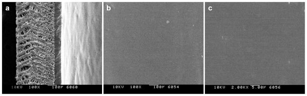
Scanning electron microscopy of polyurethane (PU) coating on (a) the edge of ePTFE graft at 100x, and on (b) the luminal surface at 100x and (c) 2000x. Scale bars: (a and b) 100 μm; (c) 5 μm.
Figure 2.
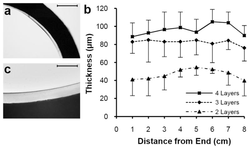
Light microscopy of thin cross sections of polyurethane (PU) coated ePTFE grafts. (a) Interface between opaque ePTFE graft wall and transparent 2-layer PU lining observed at 4x. (b) Mean ± standard deviation of PU thickness measured at 4 positions per cross section and 1cm intervals along 8cm ePTFE graft segment coated with 2, 3, and 4 deposited layers of PU on top of a base extruded layer. (c) Interface between opaque ePTFE graft wall and transparent 4 layer PU lining observed at 20x. Scale bars: (a) 500 μm; (c) 100 μm.
Figure 3.
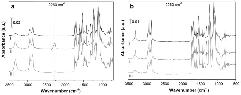
Attenuated reflection infrared spectroscopy of (a) polyurethane (PU) coated on the luminal surface of ePTFE grafts and (b) thin solvent cast PU films. Representative spectra given for (i) PU, (ii) PU subjected to isocyanate activation with hexamethylene diisocyanate, and (iii) PU modified with a heterobifunctional NH2-PEG11-triphenylphosphine linker.
2.2. Chemical Modification of ePTFE Grafts
Amine-reactive isocyanate groups were generated on PU coated grafts using a rotary reactor, which facilitated uniform mixing of reagents (Figure 4).[44] PU coated grafts were incubated for 1 h with hexamethylene diisocyanate (HDI) in the presence of triethylamine (TEA) at 50 °C, as demonstrated elsewhere.[45] ATR-IR spectroscopy detected a distinct peak at 2260 cm−1 corresponding to –N=C=O (Figure 3). A heterobifunctional linker comprised of a poly(ethylene glycol) (PEG) spacer with amino (–NH2) and triphenylphosphine (TPP) end groups (NH2–PEG11–TPP) was used to derivatize accessible surface isocyanates (Scheme 1), as confirmed by loss of the –N=C=O peak by ATR spectroscopy (Figure 3). Consistent with this finding, X-ray photoelectron spectroscopy (XPS) revealed a sharp decrease in the C (285eV) to O (532eV) ratio (Figure 5a–c and Table I) and the presence of distinct phosphorous peaks (P2p at 133eV and P2s at 200eV) (Figure 5c). The absence of fluorine peaks (Figure 5a–c) further confirmed complete coverage of ePTFE by the PU thin film. High resolution C 1s XPS (Figure 5d–f and Table I) revealed a dramatic increase in N–C=O (289.0eV) intensity and increased ether carbon content (C–O, 286.4eV) after immobilization of the PEG linker. These observations confirm the initial generation of reactive isocyanates followed by the display of TPP moieties on the luminal surface of PU-coated ePTFE grafts.
Figure 4.
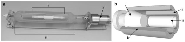
Reactor setup for chemical derivatization of PU modified ePTFE grafts. (a) 4 mm i.d. ePTFE grafts were chemically modified using a custom reactor design comprising (i) reactor housing for ePTFE graft and a (ii) DC motor that is coupled to a (iii) form-fitting rotator clamp for graft reactors to facilitate rotation along the axial length of grafts. (b) Inner construction of reactor housing for ePTFE graft comprising (i) barbed Kynar plugs to seal both ends of tubular reaction vessel; (ii) inner 5 mm i.d., 7 mm o.d. Teflon tube; (iii) 4 mm i.d. ePTFE graft; (iv) outer 7 mm i.d., 9 mm o.d. Teflon tube.
Figure 5.

Survey and high resolution X-ray photoelectron spectroscopy (XPS) of PU modified ePTFE grafts. Survey XPS were performed on the ePTFE graft lumen following (a) surface coating with PU, (b) subsequent isocyanate modification, and (c) NH2–PEG11–TPP linker immobilization. Corresponding high resolution C 1s XPS were performed on the ePTFE graft lumen following (d) surface coating with PU, (e) subsequent isocyanate modification, and (f) NH2 PEG11 TPP linker immobilization.
Table 1.
Elemental analysis of modified ePTFE grafts by XPS.
| Substrate | Survey XPS
|
High Resolution C 1s XPS
|
|||||
|---|---|---|---|---|---|---|---|
| C (%) | O (%) | N (%) | C/O Ratio | C–C (%) | C–O (%) | O–C=O N–C=O (%) | |
| PU [a] | 81 | 17 | 1.6 | 4.8 | 65 | 13 | 1.1 |
| PU NCO [b] | 86 | 13 | 0.70 | 6.6 | 74 | 6.0 | 9.2 |
| PU TPP [c] | 70 | 24 | 4.6 | 2.9 | 50 | 45 | 2.8 |
Bare polyurethane (PU);
isocyanate activated PU;
PU–NCO reacted with NH2–PEG11–TPP linker
2.3. Staudinger Ligation of Azide Probe on ePTFE
A fluorescent azide probe was used to initially assess the specificity of small molecule immobilization by Staudinger Ligation.[46] Rhodamine B and its azide analogue tetramethylrhodamine 5-carbonyl azide (Rh-N3) were reacted in parallel with PU films functionalized with TPP. Following extensive rinsing in methanol, it was evident that only Rh-N3 was covalently immobilized to TPP modified PU films (Figure 6a). This result was semi-quantitatively corroborated by UV-Vis spectroscopy (Figure 6b), and verified visually on PU-coated ePTFE grafts (Figure 6c).
Figure 6.
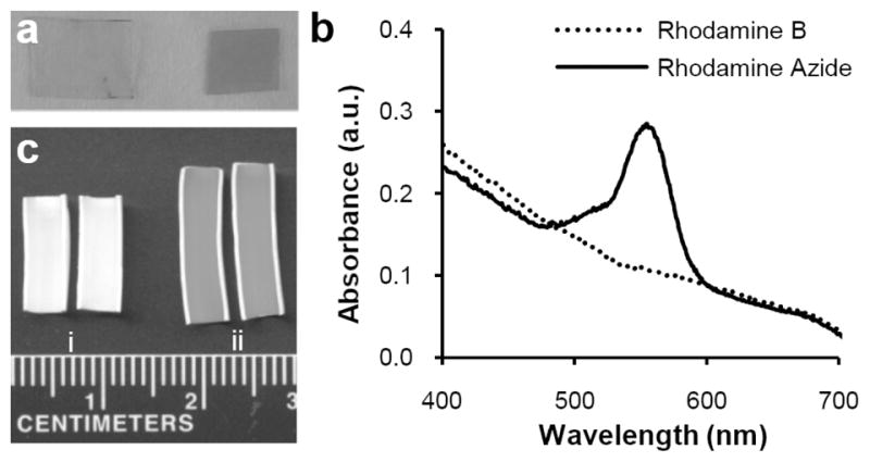
Feasibility of immobilizing azide probes by Staudinger Ligation on polyurethane films. (a) Visual confirmation of solvent cast PU films derivatized with TPP and reacted with either (left) rhodamine B or (right) rhodamine azide. (b) Solvent cast thin PU films activated with TPP anchor groups were reacted with either rhodamine B or rhodamine azide and analyzed by UV-Vis spectroscopy. (c) En face examination of TPP modified grafts following reaction with (i) rhodamine B or (ii) rhodamine azide and rinsing with methanol.
2.4. Immobilization of Thrombomodulin
TPP modified grafts were exposed to recombinant TM expressing either a single C-terminal azide moiety (TM-N3) or a native methionine (TM-methionine). Following a phosphate buffered saline (PBS, pH 7.4) rinse for 24 h, the capacity to activate PC was assessed in vitro. Grafts reacted with TM-N3 afforded a 30-fold increase in their capacity to activate aPC as compared to grafts incubated with TM-methionine (~0.4 vs ~12 ng aPC cm−2 min−1, p<0.01; Figure 7a). The density of covalently bound TM was measured using a horseradish peroxidase (HRP) conjugated antibody that recognizes the human TM EGF5–6 domain. Surface density of TM-N3 was ~170 fmol/cm2 after subtracting background binding of antibody to unmodified PU (Figure 7b).[47] The aPC generating capacity reported herein is greater than that previously reported for random immobilization strategies.[34, 37] Since the minimum aPC flux required to inhibit thrombosis has not been established, predicting in vivo performance is not feasible.
Figure 7.
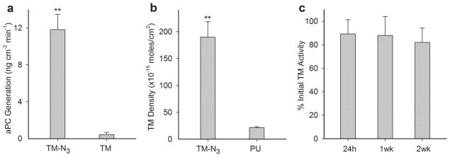
Measurement of thrombomodulin (TM) cofactor activity to generate aPC, TM surface density, and stability of immobilized TM on modified ePTFE grafts. (a) Catalytic activity of TPP modified ePTFE grafts reacted with recombinant TM expressing a C-terminal azide moiety (TM-N3) or TM containing its native C-terminal methionine. (b) Surface density of TM on grafts was quantified using a TM antibody and compared with background binding of antibody to bare PU coated ePTFE. (c) Graft activity measured as a percentage of initial levels following 24 h of mechanical shear at 500 s−1 at 37 °C and subsequent 2-week incubation in PBS at 37 °C. Data represents mean ± standard deviation for n ≥ 3 samples. Statistical difference (p < 0.01) versus control is denoted by a double asterisk.
Biostability was assessed by subjecting TM-modified grafts to PBS at a shear rate of 500 s−1 and 37 °C for 24 h, as well as to an additional 2 week period in PBS at 37 °C. Catalytic activity remained nearly constant indicating that covalently immobilized TM-N3 was unaffected by short-term exposure to arterial shear, as well as extended incubation under physiologically relevant pH and temperature conditions (Figure 7c). Notably, random amine-crosslinking techniques used to immobilize TM on ePTFE resulted in a 50% reduction in surface activity following exposure to mechanical shear for 7 hours at 37 °C.[27] Others have reported a ~30% reduction in activity when TM modified surfaces were subjected to static incubation in PBS at 37 °C for 4 weeks.[29]
2.5. In Vivo Performance of ePTFE Grafts Modified with Thrombomodulin
The ex vivo femoral arteriovenous shunt model provides a means to assess the thrombogenicity of blood contacting materials under dynamic arterial flow conditions, particularly when implanted in sub-human primates, such as the baboon, whose hemostatic system closely resembles that of man.[48–51] Platelet binding to PU coated PTFE grafts (4 mm i.d.) was assessed using an arteriovenous perfusion chamber and compared to responses observed to unmodified Dacron grafts (Figure 8).[49, 52] Cumulative platelet deposition on PU coated ePTFE was substantially lower than on Dacron grafts (0.0082 vs 1.5 billion/cm2). Since the level of platelet deposition on PU coated ePTFE grafts is too low to gauge the therapeutic efficacy of immobilized TM, we explored thrombus growth in a perfusion system in which a test graft was interposed between a collagen coated ePTFE graft, as a thrombogenic source, and a distal expansion chamber (Figure 9).[48, 49] TM modified ePTFE grafts reduced platelet deposition in the distal expansion chamber by nearly 50% when compared to unmodified PU coated grafts (n=4, p < 0.05). Since thrombin is an important physiological agonist for platelet activation,[6] the measured reduction of platelet deposition in the distal expansion chamber suggests that substantial levels of aPC are generated from the TM modified surface. In addition to attenuating thrombosis, local generation of aPC may influence the healing characteristics of implanted grafts, as late prosthetic graft failure has been attributed to progressive intimal hyperplasia, a process exacerbated by thrombin and platelet derived pro-inflammatory factors.[7, 53]
Figure 8.

Real time platelet deposition on modified ePTFE grafts in the absence of an upstream thrombus source in the baboon shunt model. (a) Shunt configuration for testing thrombogenicity of 4 mm i.d. tubular materials. (b) Representative photo of a 7 cm length bare PU coated ePTFE graft split in half lengthwise following 1 h perfusion at 100 mL/min; Arrow points in direction of blood flow. (c) Comparison of platelet deposition on bare PU coated 4 mm i.d. ePTFE (ePTFE + PU) with plain 4 mm i.d. Dacron grafts. Each data point represents mean ± standard deviation for n ≥ 3 samples. Statistical difference (p < 0.01) is denoted by double asterisk.
Figure 9.
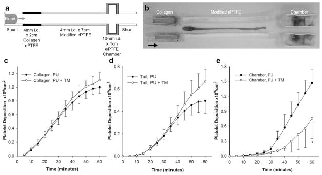
The biological function of TM modified ePTFE grafts was evaluated using a three-compartment thrombogenic device inserted into chronic arteriovenous shunts in baboons. (a) A 2 cm × 4 mm inner diameter (i.d.) segment of collagen coated ePTFE serving as a thrombin source was connected upstream of a 7 cm × 4 mm i.d. segment of test graft, and the therapeutic function of aPC generated in situ was detected in a 1 cm × 10 mm i.d. distal expansion chamber. Arrow points in direction of blood flow. (b) Representative photograph of the entire chamber assembly that tested a 7 cm TM modified ePTFE graft split in half lengthwise following perfusion for 1 h at 100 mL/min. Arrow points in direction of blood flow. Real-time platelet deposition (c) in the upstream collagen coated 4 mm i.d. ePTFE segment; (d) in the thrombus tail developing distal to collagen coated ePTFE; and (e) in the 10 mm i.d. expansion chamber distal to TM modified ePTFE grafts (PU + TM) compared with bare PU coated ePTFE controls. Each data point represents mean ± standard deviation of 4 independent studies. Statistical difference (p < 0.05) is denoted by single asterisk.
3. Conclusions
We have presented a biomimetic surface engineering approach that combines molecular engineering and orthogonal chemistry strategies to site-specifically functionalize clinical vascular prostheses with recombinant human TM that exhibit biocatalytic activity and biostability in vitro. Moreover, we have devised and tested a robust, clinically relevant in vivo model of vascular graft thrombosis in non-human primates that facilitated evaluation of the therapeutic function of bioactive TM surface assemblies. The data presented herein indicate that biologically active TM surface assemblies reduces the thrombogenic properties of blood contacting surfaces despite the presence of an upstream thrombin generating stimulus. The modular nature of heterobifunctional linker design, combined with recent advances in chemoselective techniques to modify peptides and proteins,[54, 55] will undoubtedly expand the utility of bioenzyme surface assemblies to a range of clinically important host-material interfaces.
4. Experimental
Reagents
All reagents were purchased from Aldrich, St Louis and used without further purification unless otherwise noted. Expression and purification of recombinant TM-methionine and TM-N3 are detailed elsewhere [38].
Synthesis of NH2–PEG11–TPP
NH2–PEG11–TPP was synthesized by reaction of O-(2-aminoethyl)-O′-[2-(Boc-amino)ethyl]decaethylene glycol with a pentafluorophenyl ester of TPP [46] in CH2Cl2 and 3 equiv 2,6-lutidine at 25 °C for 12 h, followed by removal of Boc using CF3COOH and purification by column chromatography. 1H NMR (400 MHz, CDCl3): δ 8.10 (dd, 1H, J = 3.6, 8), 7.83 (dd, 1H, J = 1.6, 8.4), 7.39–7.28 (m, 11H), 6.81 (m, 1H), 3.80 (brs, 2H), 3.76 (s, 3H), 3.70–3.49 (m, 46H), 2.97 (t, 2H, J = 5.2); HRMS (ESI, m/z): [M+H]+ calcd for C45H68N2O14P, 891.4408; found, 891.4396.
Modification of ePTFE grafts
5% w/v Elasthane 80A (Polymer Tech, Berkeley) in N,N-dimethylformamide (DMF) was extravasated through 4 mm i.d. ePTFE thin wall vascular grafts (Bard, Tempe) and dried under vacuum at 60 °C for 20 min. Additional PU was deposited in multiple flow-through/drying cycles over the base layer, and dried overnight under vacuum at 60 °C. PU coated grafts were inserted into tubular reactors as depicted in Figure 4 and rotated at 500rpm for surface reactions. Grafts were first reacted with HDI (16% v/v) and TEA (4% v/v) in toluene at 50 °C for 1 h and rinsed in toluene for 6 h. Isocyanate activated grafts were reacted with NH2–PEG11–TPP linker (10 mg/mL) and TEA (1% v/v) in toluene at 40 °C overnight, rinsed with toluene for 6 h, and dried under vacuum at 25 °C overnight. TPP activated grafts were reacted with 1 mg/mL tetramethylrhodamine-5-carbonyl azide (Invitrogen, Carlsbad) in 1:4 tert-butanol/PBS at 37 °C for 24 h followed by rinsing in methanol for 24 h, or reacted with 20 μM TM-N3 in PBS at 37 °C for 24 h and rinsed with PBS for 24 h. Grafts coated with PU and activated with TPP were reacted with rhodamine B or TM-methionine as controls.
Modification of polyurethane films
Thin clear PU films were solvent cast by drying 12.5% w/v Elasthane 80A in DMF for 24 h at 60 °C under vacuum. Films were subjected to isocyanate, TPP, and rhodamine reactions in a glass vial using identical conditions as graft substrates, and characterized by UV-Vis spectroscopy (Cary 50 Bio UV-visible spectrophotometer, Varian).
Surface analysis
An in-lens field-emission SEM (ISI DS-130F Schottky Field Emission SEM) operated at 10 kV was used to examine the graft luminal surface. Light microscopy images of serial thin sections of modified grafts were used to determine PU thickness. ATR-IR spectra were acquired using a FTS-4000 FT-IR spectrometer (Bio-Rad, Hercules) equipped with a wide-band MCT detector, collected with 100 scans at 2 cm−1 resolution. XPS data were recorded on an Axis Ultra X-ray photoelectron spectrometer (Kratos Analyticals, UK) equipped with a monochromatized Al Kα X-ray source.
TM graft cofactor activity assay
A 4 mm graft segment was incubated in 200 μL of 0.2 μM human protein C (Calbiochem, Gibbstown), 5 mM calcium chloride, and 2 nM human α-thrombin (Haematologic Technologies, Essex Junction) in Tris buffer (20 mM Tris, 100 mM NaCl, pH 7.5) with 0.1% bovine serum albumin (BSA) at 37 °C for 1 h, and quenched with 2 IU/mL human anti-thrombin III (American Diagnostica, Stamford) for 5 min. The generation of aPC was quantified using 0.2 mM of an enzymatically digestible chromogenic substrate, Spectrozyme PCa (American Diagnostica). TM activity was assayed after grafts were exposed for 24 h to PBS at 37 °C and 500 s−1 shear, as well as after incubation in PBS with 0.02% sodium azide at 37 °C over a two week period.
Determination of TM surface density
All assay reactions were run in a 96-well plate, per manufacturer’s instructions (American Diagnostica, Stamford). Moles of EGF5–6 domains bound to test grafts were calculated by a standard curve generated by ELISA using known concentrations of TM. At the end of each assay, graft segments were flattened between glass slides and scanned at 600 dpi using a HP ScanJet 5370C scanner and the reactive area of each test sample was measured using ImageJ software.
In vivo baboon arteriovenous shunt model
A chronic exteriorized arteriovenous shunt was implanted in male baboons, as previously described [49, 52]. All studies were approved by the Institutional Animal Care and Use Committee at Oregon Health and Science University. Mean blood flow rate through the shunt was measured continuously using a Doppler ultrasonic flow meter and held constant by an external screw clamp at 100 mL/min. Autologous platelets were radiolabeled one day prior to shunt study with Indium-111 oxine and re-injected into the baboon. Platelet deposition in the individual compartments of the shunt assembly was measured over a 60-minute perfusion period using a high sensitivity 99Tc collimator and scintillation camera (GE 400T, General Electric) imaging of the 172 keV 111In g photon peak at 5-min intervals [52].
Statistical analysis
Two-tailed student’s t-test assuming unequal variances was used to test for statistical significance between the means of two groups.
Acknowledgments
This work was supported by grants from the National Institute of Health.
Contributor Information
Zheng Qu, Departments of Biomedical Engineering and Surgery, Georgia Institute of Technology and Emory University Atlanta, GA 30322 (USA).
Dr. Sharmila Muthukrishnan, Departments of Biomedical Engineering and Surgery, Georgia Institute of Technology and Emory University Atlanta, GA 30322 (USA)
Dr. Murali K. Urlam, Departments of Biomedical Engineering and Surgery, Georgia Institute of Technology and Emory University Atlanta, GA 30322 (USA)
Dr. Carolyn A. Haller, Department of Surgery, Beth Israel Deaconess Medical Center, Harvard Medical School, and the Wyss Institute of Biologically Inspired Engineering of Harvard University Boston, MA 02115 (USA)
Dr. Sumanas W. Jordan, Departments of Biomedical Engineering and Surgery, Georgia Institute of Technology and Emory University Atlanta, GA 30322 (USA)
Vivek A. Kumar, Departments of Biomedical Engineering and Surgery, Georgia Institute of Technology and Emory University Atlanta, GA 30322 (USA)
Ulla M. Marzec, Oregon National Primate Research Center, Oregon Health and Science University, Beaverton, OR 97006 (USA)
Dr. Yaseen Elkasabi, Department of Chemical Engineering, University of Michigan, Ann Arbor, MI 48109 (USA)
Prof. Joerg Lahann, Department of Chemical Engineering, University of Michigan, Ann Arbor, MI 48109 (USA)
Prof. Stephen R. Hanson, Oregon National Primate Research Center, Oregon Health and Science University Beaverton, OR 97006 (USA)
Prof. Elliot L. Chaikof, Email: echaikof@bidmc.harvard.edu, Department of Surgery, Beth Israel Deaconess Medical Center, Harvard Medical School, and the Wyss Institute of Biologically Inspired Engineering of Harvard University Boston, MA 02115 (USA).
References
- 1.Ikada Y. Biomaterials. 1994;15:725. doi: 10.1016/0142-9612(94)90025-6. [DOI] [PubMed] [Google Scholar]
- 2.Nel AE, Madler L, Velegol D, Xia T, Hoek EMV, Somasundaran P, Klaessig F, Castranova V, Thompson M. Nat Mater. 2009;8:543. doi: 10.1038/nmat2442. [DOI] [PubMed] [Google Scholar]
- 3.Ratner BD. Biomaterials. 2007;28:5144. doi: 10.1016/j.biomaterials.2007.07.035. [DOI] [PMC free article] [PubMed] [Google Scholar]
- 4.Jordan SW, Chaikof EL. J Vasc Surg. 2007;45(Suppl A):A104. doi: 10.1016/j.jvs.2007.02.048. [DOI] [PubMed] [Google Scholar]
- 5.Gorbet MB, Sefton MV. Biomaterials. 2004;25:5681. doi: 10.1016/j.biomaterials.2004.01.023. [DOI] [PubMed] [Google Scholar]
- 6.Furie B, Furie BC. N Engl J Med. 2008;359:938. doi: 10.1056/NEJMra0801082. [DOI] [PubMed] [Google Scholar]
- 7.Qu Z, Chaikof EL. Curr Opin Immunol. 2010;22:634. doi: 10.1016/j.coi.2010.08.017. [DOI] [PMC free article] [PubMed] [Google Scholar]
- 8.Anderson JM, Rodriguez A, Chang DT. Semin Immunol. 2008;20:86. doi: 10.1016/j.smim.2007.11.004. [DOI] [PMC free article] [PubMed] [Google Scholar]
- 9.Gott VL, Whiffen JD, Dutton RC. Science. 1963;142:1297. doi: 10.1126/science.142.3597.1297. [DOI] [PubMed] [Google Scholar]
- 10.de Agostini AI, Watkins SC, Slayter HS, Youssoufian H, Rosenberg RD. J Cell Biol. 1990;111:1293. doi: 10.1083/jcb.111.3.1293. [DOI] [PMC free article] [PubMed] [Google Scholar]
- 11.Liaw PC, Becker DL, Stafford AR, Fredenburgh JC, Weitz JI. J Biol Chem. 2001;276:20959. doi: 10.1074/jbc.M010584200. [DOI] [PubMed] [Google Scholar]
- 12.Phaneuf MD, Berceli SA, Bide MJ, Quist WC, LoGerfo FW. Biomaterials. 1997;18:755. doi: 10.1016/s0142-9612(96)00193-7. [DOI] [PubMed] [Google Scholar]
- 13.Seifert B, Romaniuk P, Groth T. Biomaterials. 1997;18:1495. doi: 10.1016/s0142-9612(97)00079-3. [DOI] [PubMed] [Google Scholar]
- 14.Lahann J, Klee D, Pluester W, Hoecker H. Biomaterials. 2001;22:817. doi: 10.1016/s0142-9612(00)00244-1. [DOI] [PubMed] [Google Scholar]
- 15.Hashi CK, Derugin N, Janairo RR, Lee R, Schultz D, Lotz J, Li S. Arterioscler Thromb Vasc Biol. 2010;30:1621. doi: 10.1161/ATVBAHA.110.208348. [DOI] [PMC free article] [PubMed] [Google Scholar]
- 16.Freitas SC, Barbosa MA, Martins MC. Biomaterials. 2010;31:3772. doi: 10.1016/j.biomaterials.2010.01.097. [DOI] [PubMed] [Google Scholar]
- 17.Ito Y, Liu LS, Matsuo R, Imanishi Y. J Biomed Mater Res. 1992;26:1065. doi: 10.1002/jbm.820260808. [DOI] [PubMed] [Google Scholar]
- 18.Salvagnini C, Gharbi S, Boxus T, Marchand-Brynaert J. Eur J Med Chem. 2007;42:37. doi: 10.1016/j.ejmech.2006.07.010. [DOI] [PubMed] [Google Scholar]
- 19.Gouzy MF, Sperling C, Salchert K, Pompe T, Streller U, Uhlmann P, Rauwolf C, Simon F, Bohme F, Voit B, Werner C. Biomaterials. 2004;25:3493. doi: 10.1016/j.biomaterials.2003.10.091. [DOI] [PubMed] [Google Scholar]
- 20.Esmon CT. Biochim Biophys Acta. 2000;1477:349. doi: 10.1016/s0167-4838(99)00266-6. [DOI] [PubMed] [Google Scholar]
- 21.Esmon CT. J Biol Chem. 1989;264:4743. [PubMed] [Google Scholar]
- 22.Goddard JM, Hotchkiss JH. Prog Polym Sci. 2007;32:698. [Google Scholar]
- 23.Kishida A, Ueno Y, Maruyama I, Akashi M. Biomaterials. 1994;15:1170. doi: 10.1016/0142-9612(94)90238-0. [DOI] [PubMed] [Google Scholar]
- 24.Kishida A, Ueno Y, Maruyama I, Akashi M. ASAIO J. 1994;40:M840. doi: 10.1097/00002480-199407000-00116. [DOI] [PubMed] [Google Scholar]
- 25.Sperling C, Konig U, Hermel G, Werner C, Muller M, Simon F, Grundke K, Jacobasch HJ, Vasilets VN, Ikada Y. J Mater Sci Mater Med. 1997;8:789. doi: 10.1023/a:1018572931351. [DOI] [PubMed] [Google Scholar]
- 26.Vasilets VN, Hermel G, Konig U, Werner C, Muller M, Simon F, Grundke K, Ikada Y, Jacobasch HJ. Biomaterials. 1997;18:1139. doi: 10.1016/s0142-9612(97)00045-8. [DOI] [PubMed] [Google Scholar]
- 27.Li JM, Singh MJ, Nelson PR, Hendricks GM, Itani M, Rohrer MJ, Cutler BS. J Surg Res. 2002;105:200. doi: 10.1006/jsre.2002.6381. [DOI] [PubMed] [Google Scholar]
- 28.Sperling C, Salchert K, Streller U, Werner C. Biomaterials. 2004;25:5101. doi: 10.1016/j.biomaterials.2003.12.014. [DOI] [PubMed] [Google Scholar]
- 29.Wu B, Gerlitz B, Grinnell BW, Meyerhoff ME. Biomaterials. 2007;28:4047. doi: 10.1016/j.biomaterials.2007.06.002. [DOI] [PMC free article] [PubMed] [Google Scholar]
- 30.Yeh HY, Lin JC. J Biomater Sci Polym Ed. 2009;20:807. doi: 10.1163/156856209X426952. [DOI] [PubMed] [Google Scholar]
- 31.Jonkheijm P, Weinrich D, Schroder H, Niemeyer CM, Waldmann H. Angew Chem Int Ed Engl. 2008;47:9618. doi: 10.1002/anie.200801711. [DOI] [PubMed] [Google Scholar]
- 32.Sletten EM, Bertozzi CR. Angew Chem Int Ed Engl. 2009;48:6974. doi: 10.1002/anie.200900942. [DOI] [PMC free article] [PubMed] [Google Scholar]
- 33.Watzke A, Kohn M, Gutierrez-Rodriguez M, Wacker R, Schroder H, Breinbauer R, Kuhlmann J, Alexandrov K, Niemeyer CM, Goody RS, Waldmann H. Angew Chem Int Ed Engl. 2006;45:1408. doi: 10.1002/anie.200502057. [DOI] [PubMed] [Google Scholar]
- 34.Kalia J, Abbott NL, Raines RT. Bioconjug Chem. 2007;18:1064. doi: 10.1021/bc0603034. [DOI] [PubMed] [Google Scholar]
- 35.David R, Richter MP, Beck-Sickinger AG. Eur J Biochem. 2004;271:663. doi: 10.1111/j.1432-1033.2004.03978.x. [DOI] [PubMed] [Google Scholar]
- 36.Suzuki K, Kusumoto H, Deyashiki Y, Nishioka J, Maruyama I, Zushi M, Kawahara S, Honda G, Yamamoto S, Horiguchi S. EMBO J. 1987;6:1891. doi: 10.1002/j.1460-2075.1987.tb02448.x. [DOI] [PMC free article] [PubMed] [Google Scholar]
- 37.Soellner MB, Dickson KA, Nilsson BL, Raines RT. J Am Chem Soc. 2003;125:11790. doi: 10.1021/ja036712h. [DOI] [PubMed] [Google Scholar]
- 38.Cazalis CS, Haller CA, Sease-Cargo L, Chaikof EL. Bioconjug Chem. 2004;15:1005. doi: 10.1021/bc049903y. [DOI] [PubMed] [Google Scholar]
- 39.Parkinson JF, Nagashima M, Kuhn I, Leonard J, Morser J. Biochem Biophys Res Commun. 1992;185:567. doi: 10.1016/0006-291x(92)91662-a. [DOI] [PubMed] [Google Scholar]
- 40.Kiick KL, Saxon E, Tirrell DA, Bertozzi CR. Proc Natl Acad Sci U S A. 2002;99:19. doi: 10.1073/pnas.012583299. [DOI] [PMC free article] [PubMed] [Google Scholar]
- 41.Dargaville TR, George GA, Hill DJT, Whittaker AK. Prog Polym Sci. 2003;28:1355. [Google Scholar]
- 42.Klee D, Hocker H. Polymers for biomedical applications: Improvement of the interface compatibility. Vol. 149. Springer-Verlag Berlin; Berlin: 1999. [Google Scholar]
- 43.Lamba NMK, Woodhouse KA, Cooper SL, Lelah MD. Polyurethanes in biomedical applications. CRC Press; Boca Raton: 1998. [Google Scholar]
- 44.Jordan SW, Faucher KM, Caves JM, Apkarian RP, Rele SS, Sun XL, Hanson SR, Chaikof EL. Biomaterials. 2006;27:3473. doi: 10.1016/j.biomaterials.2006.01.009. [DOI] [PubMed] [Google Scholar]
- 45.Freijlarsson C, Wesslen B. J Appl Polym Sci. 1993;50:345. [Google Scholar]
- 46.Saxon E, Armstrong JI, Bertozzi CR. Org Lett. 2000;2:2141. doi: 10.1021/ol006054v. [DOI] [PubMed] [Google Scholar]
- 47.Weisel JW, Nagaswami C, Young TA, Light DR. J Biol Chem. 1996;271:31485. doi: 10.1074/jbc.271.49.31485. [DOI] [PubMed] [Google Scholar]
- 48.Cadroy Y, Maraganore JM, Hanson SR, Harker LA. Proc Natl Acad Sci U S A. 1991;88:1177. doi: 10.1073/pnas.88.4.1177. [DOI] [PMC free article] [PubMed] [Google Scholar]
- 49.Hanson SR, Griffin JH, Harker LA, Kelly AB, Esmon CT, Gruber A. J Clin Invest. 1993;92:2003. doi: 10.1172/JCI116795. [DOI] [PMC free article] [PubMed] [Google Scholar]
- 50.Hanson SR, Sakariassen KS. Am Heart J. 1998;135:S132. doi: 10.1016/s0002-8703(98)70241-8. [DOI] [PubMed] [Google Scholar]
- 51.Byrom MJ, Bannon PG, White GH, Ng MK. J Vasc Surg. 2010 doi: 10.1016/j.jvs.2009.10.080. [DOI] [PubMed] [Google Scholar]
- 52.Jordan SW, Haller CA, Sallach RE, Apkarian RP, Hanson SR, Chaikof EL. Biomaterials. 2007;28:1191. doi: 10.1016/j.biomaterials.2006.09.048. [DOI] [PubMed] [Google Scholar]
- 53.McNamara CA, Sarembock IJ, Gimple LW, Fenton JW, Coughlin SR, Owens GK. J Clin Invest. 1993;91:94. doi: 10.1172/JCI116206. [DOI] [PMC free article] [PubMed] [Google Scholar]
- 54.Chen I, Ting AY. Curr Opin Biotechnol. 2005;16:35. doi: 10.1016/j.copbio.2004.12.003. [DOI] [PubMed] [Google Scholar]
- 55.Hackenberger CPR, Schwarzer D. Angew Chem Int Ed Engl. 2008;47:10030. doi: 10.1002/anie.200801313. [DOI] [PubMed] [Google Scholar]