

1. Introduction
In his 1665 treatise, Micrographia, Robert Hooke described the many observations he had made using a microscope, including compartment-like structures in cork samples that he termed ‘cells’.1 In the three and a half centuries since Hooke’s day, both the microscope and our understanding of the cell have been vastly improved upon, and the current outlook suggests that the symbiotic relationship between the microscope and the cell will continue to flourish into the foreseeable future. The cell is a basic yet complicated ‘unit’ of interest to biology, just as the atom is to chemists. Ultimately, scientists want to ‘see to believe’ when it comes to an explanation of the complex inner workings of cells, but therein lies a complication. Seeing is not always a possibility in biological systems. Size, speed, sensitivity, and additional concerns plague the microscopist who wants to peek inside of a cell. Enter a variety of molecular and nanoparticle probes that are capable of tagging and pinpointing the location of biological components that would otherwise be invisible under the microscope. Advances in laser, camera, and imaging processing technologies have also played a crucial role in the burgeoning field of single cell imaging, because they have brought into view the fast processes that would normally escape the human eye.
The purpose of this review is to highlight the key advances that have occurred in the past several years in the field of single cell optical imaging. It is not our intent to provide a comprehensive review of the types of experiments or the areas of cell research that are ongoing. Reviews with a distinctly biological flavor have been published recently, and these alternative reviews focus on specific details of the cell and the processes that occur within.2-7 Likewise, exceptional review papers that have discussed the full spectrum of nanoparticle probes and their properties have appeared recently.6-12 This review is designed to give an overview of the tools that are being specifically used to accomplish single cell imaging. As such, much of our emphasis in the first several sections of this paper is on imaging platforms, with a focus on design details that are important to single cell imaging experiments. Next we emphasize specific imaging experiments that highlight the types of findings that are possible at the nexus of microscopy, nanoprobes, and live cells. Particular attention is paid to the emerging orientation and rotational tracking of single probes linked to mechanistic functions and differentiated structures of biological interest. Finally, we provide a brief, yet rather complete, summary of single cell manipulation techniques.
2. Fluorescence imaging
Due to its high sensitivity and specificity, florescence microscopy is commonly used for a broad range of applications in cell biology. Among other purposes, fluorescence microscopy can be used to measure properties of molecular and cellular movements;13-14 the cellular location of biomolecules15 and interactions between biomolecules.16 The high specificity of fluorescence microscopy is in part the result of the discovery and subsequent cloning of the green fluorescent protein (GFP) and its many variants, which made it possible to express a fluorescent label fused to a protein of interest throughout a given cell or organism. This break-through resulted in the awarding of the Noble Prize in Chemistry to Osamu Shimomura, Martin Chalfie, and Roger Y. Tsien in 2008.
A large number of fluorescence imaging techniques have been developed. Lakowicz’s classic book17 is highly recommended for acquiring deep understanding on fluorescence spectroscopy. It is nearly impossible to cover all of these techniques in one review article. In this section, we focus on several hot areas that have seen many recent developments in instrumentation and methodology for single cell imaging. A notable omission from this review is near-field optical scanning microscopy (NSOM). Readers interested in NSOM should refer to other excellent review articles.18-19
2.1 Confocal single-photon and multi-photon fluorescence
Confocal fluorescence microscopy and multiphoton excitation fluorescence (MPEF) microscopy are relatively mature methods and widely used nowadays. We will start with a very brief introduction to these two methods and focus on recent technical advances in terms of spatial resolution, temporal resolution, and sensitivity, with a few arbitrarily selected applications. In light of the recent and fast development of far-field, super resolution optical imaging techniques, this review will emphasize the spatial resolution currently achievable in these techniques, especially with the applications of lasers and high numerical aperture (NA) microscope objectives.
2.1.1 Optical sectioning of confocal fluorescence microscopy
Conventional wide-field, epi-fluorescence microscopy offers submicron spatial resolution and excellent temporal resolution for observation of biological structure and dynamics in live cells. However, epi-fluorescence microscopes do not have any element other than the objective to discriminate background fluorescence originated from out-of-focal plane fluorophores. This results in a blurry image if three-dimensional (3D) objects, e.g., cells, are imaged.
This problem was not solved until the advent of confocal microscopy. The confocal concept was first introduced by Minsky20-21 and since that time, confocal microscopy has become well-developed and routinely used in many different areas of science. In confocal fluorescence microscopy, point illumination is used and out-of-focal plane fluorescence is effectively rejected by placing a pinhole before the detector at a plane conjugate to the illumination focal plane. By using this configuration, from which the term “confocal” stems, imaging of thin slices along the axial direction in intact cells, tissue or even animals becomes possible. This major advantage of confocal microscopy is also referred to as “optical sectioning” or “depth discrimination” and it helps in the construction of 3D profiles from thick samples. Although confocality can also be realized in scattering mode, fluorescence-mode confocal systems are most commonly used. A simple schematic of an optical path in a fluorescence confocal microscope that demonstrates the sectioning capability is shown in Figure 1.
Figure 1.

A schematic representation of the optical path in a point-scanning confocal fluorescence microscope. The collimated excitation beam (solid blue) is directed to the microscope objective by a dichroic mirror and focused onto the sample. The fluorescence signal (dashed blue) emanating from the sample in focus is collected by the same objective and imaged through a pinhole onto a detector. The off-focal plane signal (dashed red and green) is rejected by the pinhole.
2.1.2 Lateral and Axial resolution
Point spread function and spatial resolution of conventional far-field optical microscopy
The sectioning capability of confocal microscopy clearly indicates an improved axial resolution over other modes of microscopy. In fact, both lateral and axial resolution can be improved by confocal microscopy. Resolution here refers to the minimum distance between distinguishable objects in an image. Before presenting a detailed discussion of confocal microscopy, it is necessary to briefly review the definition of point spread function (PSF) in optical microscopy.
Because of diffraction, light emitted from a point source, even using an ideal objective, cannot be imaged to a point in the image space, but rather one obtains a 3D light intensity distribution. Sir George Airy first derived the mathematical expression for the intensity distribution originating from a point light source as a function of the distance from a small unobstructed circular aperture pupil. In microscopy, the objective lens behaves the same as an aperture. The image pattern coming out of an objective lens is thus called Airy disk, and it consists of a central brightest disk with progressively dimmer concentric disks (diffraction rings). Mathematically, the Airy disk pattern is related to the first-order Bessel function of the first kind. The diameter of central disk is called one Airy unit (1AU), which is:
| (1) |
where λ is the wavelength of the light passing through the lens, and NA is the numerical aperture of the objective lens.
Actual resolution is determined by the size of the Airy disk. Currently, the most commonly used definition of resolution is Rayleigh’s criterion, which states that two objects are considered to be laterally resolved if the central maximum of one point object overlaps with the first minimum of the other. This corresponds to the distance given by: 22-23
| (2) |
where λDet is the wavelength used in detection of the image pattern. Note that Rayleigh’s resolution criterion is NOT a law of physics but rather, as conceived by Rayleigh: “…is convenient on account of its simplicity and it is sufficiently accurate in view of the necessary uncertainty as to what exactly is meant by resolution.”
It also should be noted that readers need to be careful about the current use of “resolution” in the literature. There are other criteria of considerable interest, e.g., Sparrow criterion, which states that two point sources can just be resolved when the second derivative of the total intensity profile of the two points in the image vanishes on-axis. In some cases, the intensity minimum in Rayleigh’s definition is difficult to assign, or the Rayleigh criterion does not best represent the separation of two neighboring point objects. Resultantly, using the full width at half maximum (FWHM) of the detection PSF as resolution becomes more and more popular. In this review, in order to minimize confusion, we will honor this emerging practice but specify a FWHM resolution (FWHM) or a Rayleigh resolution (Δ). For example, the lateral resolution, according to the FWHM criterion, of diffraction limited optical microscopy is:24
| (3) |
The axial distribution of light intensity was calculated by Linfoot and Wolf in 1953, and the distance from the center of the 3D diffraction pattern to the first minimum in the z-direction for small NAs (<0.5) is given by:25
| (4) |
and for large NAs:
| (5) |
Similarly, we can obtain the axial resolution according to FWHM criterion for small NAs (<0.5):
| (6) |
and for large NAs:
| (7) |
Using different criteria, one obtains similar expressions but with slightly different coefficients.
The axial resolution should not be confused with the “depth of field” or “depth resolution” in some literature, which is defined as the width of the emission-side diffraction pattern at 80% of the maximum intensity. It describes the depth of the image that appears to be sharply in focus. Again, the 80% is arbitrarily defined.
Resolution of confocal fluorescence microscopy
In confocal microscopy, because of the application of the pinhole, extra discrimination ability can be provided. For imaging a point, a confocal fluorescence microscope generates two point images: one by projecting the laser beam into the object space, the other by projecting the fluorescence signal from a point source into the image space. The total PSF (PSFTot) of a confocal microscope is the convolution of the two PSFs:
| (8) |
where PSFIll is the intensity distribution of the focused laser spot and PSFDet is the intensity distribution of the fluorescence signal behind the pinhole.23-24 The pinhole is never infinitely small and PSFDet is always larger than PSFIll. In practice, the pinhole size is usually set at 0.8-1.0 AU to ensure that enough photons are being collected. Here the airy unit is defined in Equation 1 and used primarily for normalizing the actual pinhole size in accordance with the illumination light wavelength and the NA of the objective. Under this condition, the optical resolution is dominated by the PSFIll:
| (9) |
Similarly, the axial resolution for small NAs (<0.5) is:
| (10) |
and for large NAs is:
| (11) |
These equations are strikingly similar to those for epi-fluorescence microscopy, except that λDet is replaced by λIll in confocal microscopy. That is, the optical resolution, both axial and lateral, depends only on the wavelength of excitation. Therefore, confocal microscopy improves the resolution by a factor of λem/λex as a result of the Stokes shift.26
At the first look, it is counter-intuitive that confocal microscopy has excellent sectioning capability but the theoretical axial resolution is not drastically improved as compared to epi-fluorescence microscopy under practical conditions. This is not surprising because in reality, the resolution is related to the signal-to-noise ratio (S/N) as will be discussed in a later part of this section. Confocal type detection effectively removes out-of-focal plane fluorescence, leading to a much cleaner background, hence the better axial resolution.
Laser illumination and resolution
The above equations are derived by assuming that the lens aperture is homogeneously illuminated. In practice, this is not always true. First, even for lamp excitation, because of aplanatic projection, the wavefront is spherical, leading to an amplitude distribution weighted by , where α is the angle of focusing. Second, current commercial instruments use a laser beam as the excitation source, which has a Gaussian intensity profile. The Gaussian beam waist, after being focused by a lens can be written as:27
| (12) |
where ω0 is the 1/e2 radius of the Gaussian beam after the lens, f is the focal length of the lens, and d is the active lens diameter. For a laser beam filling the full back aperture of a microscope objective (the beam waist 2ω before the lens approaching the diameter of the lens), we obtain:
| (13) |
and
| (14) |
Equations 12-14 gives an excellent approximation of the size of the focused laser spot for under-filled laser beams, and we can see that the larger the incident laser beam, the more tightly it is focused. Overfilling the back aperture of the microscope objective will expand the focused beam.27 In fact, as the incident beam becomes larger, the incident wavefront becomes more like a plane wave and Equations 9-11 apply. Numerical simulations show that the effect of amplitude variations across the wavefront on the PSF profile is negligible in this situation. Thus, Equations 9-11 are good estimations for lamp excitation and overfilled laser beams.
Effect of pinhole size
When the pinhole diameter is reduced well below 0.8 AU, the resolution of confocal microscopy is slightly improved and affected by both PSFIll and PSFDet. At the limiting case, where the pinhole is sufficiently small (<0.25 AU), the excitation and detection PSFs are identical in shape but slightly different in the dimension because of the Stokes shift between illumination and emission. Consider the most simplified case where the Stokes shift is negligible, the intensity PSFTot can be written as:
| (15) |
A good approximation of the spatial resolution is:
| (16) |
where β is the ratio λIll/λDet. Equation 16 applies to both lateral and axial resolutions. When the Stokes shift is sufficiently small (β approaches 1), the resolution of confocal microscopy is improved by a factor of . Note in this case, the Rayleigh criterion is no longer a good approach to estimate the resolution because the position of the first minimum does not change upon squaring of the PSF.
For pinhole size between 0.25 and 0.8 AU, further approximation needs to be taken in order to obtain an analytical expression of the resolution. The improvement factor is more readily obtained through experiments.
Effective resolution
The effective resolution of a microscope depends on a number of complex parameters. The best resolution can be obtained under ideal conditions, i.e., perfect optical alignment, minimal optical aberrations, absence of refractive index mismatch at the interfaces, good S/N per pixel, and appropriate data sampling frequency. The depth within the specimen where an optical slice is to be measured also affects the resolution, and this will be discussed in the next section. Although modern optics have improved optical performance, it is nearly impossible to achieve theoretical resolution as ideal conditions are never met. Noise of various kinds, e.g., thermal noise, detector noise, stray light, shot noise, etc., decreases the S/N and affects the image contrast and resolution adversely. Another factor is sampling frequency, i.e., number of pixels sampled per resolution unit. If the sampling frequency is too low, it is less likely that a pixel will fall exactly at the peak or valley in the PSF, leading to pixelation and reduced image contrast. The Nyquist sampling criterion states that resolution and contrast can be preserved if sampling at the rate of at least 2.3 pixels per resolution element, i.e., FWHM of PSF.28-29 Finally, optical aberrations originating from the microscope objective and refractive index mismatch have been discussed elsewhere.30-31
2.1.3 Multi-photon excitation fluorescence microscopy
Similar to confocal microscopy, MPEF microscopy adopts the approach of point illumination and imaging through scanning and also offers excellent sectioning capability. The two-photon absorption process was predicted by Nobel Laureate Maria Göppert-Mayer in 1931.32 Two-photon excitation (2PE) fluorescence from CaF2:Eu2+ with a laser source was first reported by Kaiser and Garrett in 1961.33 For many years, the application of two-photon and multi-photon absorption was mainly limited to spectroscopic studies. MPEF microscopy became practical with the emergence of mode-locked, femtosecond lasers with high peak power and a repetition rate of ~100 MHz.34 The viability of this microscope in biology was demonstrated by imaging live cultured pig kidney cells. After a brief discussion on the actual multi-photon excitation process, this sub-section will focus on resolution and imaging depth, with comparisons made to confocal microscopy, as appropriate.
The multi-photon excitation process
The most noticeable feature of MPEF microscopy is that it involves a process in which multiple photons are absorbed simultaneously by a fluorophore, where “simultaneous” refers to the time scale of ~1 femtosecond (10−15 s), and the number of photons can be 2, 3, …, while only one fluorescence photon is produced. MPE processes yield small absorption cross sections. For example, two-photon absorption cross sections (σ) commonly fall in the range of 10−47-10−49 cm4s/photon.35-36 The low absorption cross sections need to be compensated for by using a higher excitation intensity, which is achieved with tight focusing provided by a high NA objective in combination with pulsed laser illumination.
MPEF imaging allows the usage of IR laser for illumination and offers excellent axial sectioning and lateral resolution comparable to that of one photon excitation (1PE) confocal fluorescence microscopy. IR photons are less prone to be absorbed by cells and tissues than the higher energy photons used in 1PEF imaging. Because of the confined excitation under MPEF, regions situated outside the excitation-cone-waist do not suffer from photobleaching.37-39 Thus, MPEF microscopy retains the advantages of a single-photon confocal fluorescence microscopy and gains the absence of out-of-focus photo-damage of the sample.
Furthermore, in living specimens, endogenous fluorophores, e.g., NAD(P)H, flavins, lipofuscin, melanin, and porphyrins, etc., can be directly excited by using 2PE, providing the opportunity for label-free imaging.40-42 All these features make MPEF microscopy an ideal tool for imaging biological cells.40,43-54
Resolution of multi-photon fluorescence microscopy
MPEF’s key advantage over confocal microscopy is MPEF’s impressive ability to detect and image light-scattering samples. In the absence of other secondary processes (e.g., photobleaching, saturation effect, etc.), the intensity of MPE fluorescence follows higher power law dependence on the illumination intensity ‘I’, i.e., I2 and I3 dependence for 2PE and three photon excitation (3PE), respectively. The probability of excitation is maximal at the excitation-cone-waist, but the probability drops sharply outside of that focal point and also to either side of the focal plane. Thus, the MPE-generated fluorescence process is highly localized to the focal point as compared to the 1PE process. As a result, photon emission originates from the highly localized region, and MPEF-based instruments are not constrained to the same designs as 1PE.
Because the background fluorescence that originates from out-of-focal plane is avoided with MPEF, no confocal spatial filter (i.e., the pinhole) is required, and a non-descanned wide-field detector can be implemented.55 Such an instrument setup leads to a marked improvement in detection sensitivity over 1PE instruments, since essentially no background fluorescence occurs while the scattered fluorescence originates from a highly pinpointed region. Thus, the lateral resolution of MPEF microscopy is excellent compared to 1PE even though a longer wavelength of light is used. This design also results in improved imaging depth, but that discussion will be delayed until the discussion on lateral resolution is completed.
The true lateral spatial resolution, taking 2PE fluorescence (2PEF) microscopy as an example, can be estimated from its total PSF when a pinhole is not used:
| (17) |
Compared to 1PE confocal fluorescence microscopy with the same fluorophores, in 2PEF microscopy, the application of an IR laser that has a wavelength approximately twice as that used in 1PEFM expands the MPE PSFIll by a factor of ~2,56 while the square of PSFIll due to the second order photon process reduces the FWHM of PSFTot by a factor of . The overall resolution, both laterally and axially, is ~ times worse than that of 1PEFM.
As explained above, MPEF microscopy does not require a pinhole. However, it has been shown that the usage of a pinhole actually improves the resolution in most cases.57-58 The PSF total in the presence of the pinhole becomes:
| (18) |
from which the spatial resolution can be estimated. Note that for imaging deep into the specimen, signal photons are in the visible range and suffer from scattering, making it difficult to image through a pinhole. So under this design, pinholes actually degrade the performance.52,59 In such cases, putting a PMT detector with large active area close to the objective is usually advantageous.60
Imaging depth
Another important feature of MPEF microscopy is its ability to image deep into the specimen at high-resolution. An excellent and detailed paper on the limits to two-photon microscopy was written by Theer and Denk,61 and readers are referred to this paper for an in-depth discussion on the topic. Here, we present a brief discussion concerning MPEF’s imaging depth.
The greatest imaging depth, or depth-limit, has been defined as the focal depth whereupon background fluorescence and signal fluorescence become equal.61 However, imaging depth cannot be improved upon ad infinitum. Imaging depths in the range of 0.5 to 1.0 mm are quite common with MPEF, in comparison to ~100 Rm for 1PE confocal fluorescence imaging.45,61-62 Imaging at depths as great as 1.6 mm within tissues have been achieved.63 As deeper imaging is attempted into thicker samples, fluorescence that occurs near the sample surface proves to become a hindrance to image contrast, and eventually all signal can be lost.61 However, it has been found that the depth limit can be slightly increased by increasing the effective numerical aperture, decreasing the laser-pulse duration, or by using isotropic samples that are properly stained. More recently, promising attempts at improving the imaging depth and image contrast have been also accomplished by working with photoactivatible fluorophores.55
2.1.4 Recent developments of scanning single-photon and multi-photon fluorescence microscopy in cell imaging
Since the development of scanning confocal fluorescence microscopes, there has been significant progress in lasers, scanning systems, fluorescence probes, and labeling techniques. Single photon confocal and multi-photon excitation fluorescence microscopy are widely used in combination with other fluorescence techniques, e.g., polarization, fluorescence lifetime (FLIM), fluorescence resonance energy transfer (FRET), fluorescence correlation spectroscopy (FCS), fluorescence recovery after photobleaching (FRAP),64 etc., to get insight into various cellular processes.
The recent effort of scanning fluorescence microscopy includes improving the performance of imaging in spatial resolution, temporal resolution, sensitivity, and probes for imaging. Recently developed 4pi- and stimulated emission depletion (STED) microscopy have pushed the scanning fluorescence microscopy resolution to a regime of ~20 nm. This part will be reviewed in Section 2.2.
By focusing laser beams to the diffraction limit through high NA objectives, the probe volume can be drastically reduced, leading to a suppressed background. In the combined use of highly sensitive avalanche photodiode detectors (APD), the S/N of single photon confocal or MPE fluorescence microscopy can be greatly improved, and detecting single molecules becomes possible. For example, single molecule FCS has been used to study the diffusion of green fluorescent protein (GFP)-tagged proteins, protein-protein interactions, membrane trafficking, and nuclear architecture and function in live cells.65-68 A more recent trend is directly tracking individual molecules/nanoparticles in the 3D translation space and orientation space in live cells, which will be reviewed in Section 5. By spreading the single molecule image into a line image using a grating, or adopting a two-channel detection scheme, one can obtain spectroscopic information. One example is single molecule FRET where two channels of color information are obtained simultaneously (Section 2.5).
2.1.5 Improving temporal resolution
One critical element in live cell imaging is time. All biological processes have a characteristic time course, for which the microscopic system must be able to match in order to extract useful information. Although early scanning type microscopes are relatively slow, newer technology with sufficient temporal resolution makes the study possible for many biological phenomena. For example, by applying quantitative time lapse confocal imaging, Hirschberg et al. studied the transport pathways and intermediates involved in the transport of secretory cargo from the Golgi apparatus to the plasma membrane.69 Using different labeling techniques and confocal imaging, Moreno et al. showed that two distinct populations of secretory vesicles exist in neuroendocrine cells and suggested that these populations should be considered for describing vesicle related dynamics.70 Point-scanning confocal microscopy systems have also been frequently used in imaging various organelles in different cell lines. For example, Villa et al. took advantage of confocal imaging to study the morphology and distribution of mitochondria in healthy and multidrug-resistant carcinoma cells.71 Using rhodamine 123 and dimethylaminostyryl-methylpyridiniumiodine as mitrochrondrial fluorescent probes, they found that two different subpopulations of mitochondria having different localization, morphology, and activity exist in carcinoma cells. Kuznetsov et al. used time lapse confocal fluorescence microscopy to study mitochondrial dynamics in human pancreatic cells.72 They found the existence of very complicated spatial organization and dynamics inside these cells and suggested that such complex patterns of dynamics could be linked to other cellular systems and processes. By imaging fibrotic mouse and human lungs, Rock et al. demonstrated unexpected heterogeneity of stromal cells in fibrotic lesions.73 Aided by confocal fluorescence microscopy systems, a tremendous amount of work has also been performed to study the calcium dynamics in living cells using calcium sensitive fluorophores. There is a plethora of other work (both recent and earlier) in which confocal fluorescence microscopy has been used as an important tool for cell imaging. The above examples are representative of the kinds of work being accomplished in this area of research.
Limiting factor
In conventional microscopy, a wide object field is imaged at once, so it is considered a parallel image acquisition method. In contrast, in confocal fluorescence microscopy, only a single or a few object points are imaged at a time, making confocal fluorescence microscopy a serial image acquisition method. Scanning is required to obtain an optical section with a reasonable size (e.g., 200×200 pixels), which takes ~1 s. Four types of confocal scanning systems are commercially available: sample scanning, laser scanning, disc scanning and differential disc scanning, and slit or line scanning. Each scanning system has its merits and demerits.
Sample-scanning
The original versions of confocal microscopes20,74-76 were of the sample scanning type and a number of excellent works in biological studies have been published on sample scanning confocal systems.77-78 In this approach, the specimen is moved on a xyz-piezo stage across a stationary, focused laser spot. Since all the optical axes remains stationary, this configuration offers the best image quality and requires minimal post-acquisition data processing. The field of view is not limited by the type of objective used. Objectives not corrected for off-axis aberrations (coma, field curvature, astigmatism, etc.), i.e. ‘non-plan’ objectives, can be used. Recent piezoelectric stages offer sub-nanometer resolution and precision in scanning, making high resolution imaging possible. However, the major disadvantage of sample scanning is that they are relatively slow for real-time imaging due to the requirement of moving the scanning stage. Sometimes mechanical vibration of the stage can distort the soft, live specimen.
Laser-scanning
An alternative to sample scanning is laser scanning, in which the illumination spot is raster-scanned while the sample is kept stationary. All beam-scanning approaches require a microscope objective that shows excellent optical quality throughout the entire field of view, i.e., both on- and off-axis. Thus, only objectives labeled ‘plan’ with flat-field correction are appropriate for beam scanning purposes. There are different beam scanners available: linear galvanometric scanner, resonant scanner, acousto-optical deflectors, and polygon mirror scanner.
Galvanometric scanning was introduced by Åslund et al.79-80 and first used by Amos et al.81 and White et al.82 in biological research. In such scanning systems, two mirrors separately mounted to linear galvanometer motors scan the laser beam relative to the sample and descan the fluorescence signal simultaneously. Resonant scanning is a more advanced form of galvanometric scanning. The major force driving the mirror comes from a torsion spring that vibrates close to its resonant frequency.83 Resonant scanning offers a faster scan speed. However, it does not allow the access to an arbitrary spot within the scanning range.84 In both approaches, one mirror is designed to scan the fast axis and the other for the slow axis. Scanning speed is mainly limited by the mechanical properties of the scanning mirror assembly.
Acousto-optical deflector (AOD)-based scanning further improves the scanning speed of the laser beam by employing an acoustic wave to modulate the optical property of a birefringent crystal. Light passing through the crystal will be deflected at an angle that depends on both the frequency of the acoustic wave and the wavelength of light.78,84 Although AOD scanners quickly move the beam, they have lower reflection efficiency. Also, chromatic correction is required to descan the fluorescence because the reflection angle is wavelength dependent for AOD.
In polygonal mirror scanning, a multifaceted polygonal mirror attached to a motor-driven shaft provides fast beam scanning along the x-axis (fast axis). A second mirror mounted to the linear galvanometer and synchronized to the fast axis mirror scans the slow axis. As the shaft rotates, the different mirror facets are accessed, resulting in the beam scanning along the fast axis. The polygon size and number of facets are determined by the beam diameter, angular deviation, data points per scan, and duty cycle. One problem of this scanning configuration is that any imperfection in the mirror facets results in a faulty scanning pattern.84-85
Disc-scanning
One way to significantly increase the imaging speed is by illuminating multiple spots in the focal plane and detecting signals from these spots simultaneously. Disc scanning confocal (DSC) systems utilize this concept with a disc (e.g., Nipkow disc) bearing a series of carefully designed pinholes and/or slits. Parallel signals can be detected with a charge-coupled device (CCD) or complementary metal-oxide-semiconductor (CMOS) camera. The speed of DSC is determined by the rotation speed of the disc as well as the number of pinholes/slits. The resolution is determined by the design and size of pinholes/slits in the Nipkow disc. DSC systems offer scanning speeds close to conventional wide-field microscopes and can go as high as 700 frames/s, thereby approaching the limit of current array-based CCD/CMOS cameras.
Depending on their design, three types of DSC systems are in practice: tandem, single-sided, and Yokogawa microlens. Tandem DSC, the earliest version of DSC, consists of a disc having a number of pinholes arranged in a symmetric pattern of right- or left-handed spirals.86-87 Illumination and detection is performed through different sets of pinholes on the same disc. In single-sided DSC, pinholes are arranged in a series of concentric circles, and the same sets of confocal pinholes illuminate and detect the sample.88 This design offers a simpler optical path and also faster scanning speed than the tandem design. A slight variation of DSC, with an even simpler design, utilizes a disc having multiple slits.89-90 It is apparent that in DSCs discussed above, a large fraction of excitation light is blocked by the disc, leading to a low throughput. Yokogawa Electric came up with the idea of using one more Nipkow disc having microlens aligned towards the illumination side. Designing a disc having thousands of aberration free lenses is expensive and difficult; however, such a disc significantly improves the transmission efficiency of the excitation light from 142% in conventional DSC to about 40-60%.91-92
Cross-talk between pinholes is a common problem for the Nipkow disc. Cross-talk is negligible at the focal plane but becomes increasingly worse away from the focus because the detector sees significant amounts of off-focal plane background from neighboring pinholes. The axial resolution and optical sectioning capability of DSC systems is lower than that of single-point scanning confocal systems.93-95 The cross-talk problem can be minimized by utilizing the differential disc scanning approach,96-100 in which the approximate inter-pinhole cross-talk background is measured using a second CCD. Better image quality can be obtained by subtracting suitably weighted background from the primary image.101 By imaging fibroblast cells stained with Oregon Green-conjugated antibodies, it has been demonstrated that this approach enhances both lateral and axial resolution.102
DSC microscopes offer excellent temporal resolution, and thus have found many applications for the study of various dynamic cellular processes. Similar kinds of studies for point-scanning confocal fluorescence microscopy can be carried out using DSC microscopes but with better temporal resolution and lower illumination doses.103-106 Recently, DSC microscopes are also getting attention in nano-bio research. There have been concerns regarding the bio-hazard of smaller nanoparticles. For example, Jiang et al. used time lapse DSC microscopy to study exo- and endocytosis of 4-nm zwitterionic quantum dot (QD) nanoparticles by live HeLa cells.107 They demonstrated that internalization starts after the threshold density is reached, and particles accumulate in the plasma membrane prior to internalization. They found that a significant fraction of endocytosed particles accumulated in lysosomes, while the rest were actively transported to the cell periphery and exocytosed.
Slit scanning
Slit scanning can be viewed as a slightly different version of DSC, where a slit of excitation light is scanned across the specimen to increase the imaging speed. Correspondingly, fluorescence is imaged on to a 1D CCD array using a confocal slit aperture. This approach offers a scanning speed similar or better than that of DSC systems, but a much simpler instrument design.108 However, the slit aperture cannot provide axial resolution as good as that of a point scanning confocal instrument.83,93,109
Multi-focal scanning for MPEF microscopy
MPEF microscopy can adopt both sample-scanning and laser-scanning approaches as in 1PE confocal microscopy. However, MPE requires a tightly focused laser beam so that the DSC cannot be applied. Multi-focal scanning, originally implemented in 1998,110-111 can be viewed as a comparable version of disk-scanning in MPE and offers faster scanning. In this approach, the sample is illuminated by an array of focal points using a rotating/static microlens array110-111 (type I), or cascading beam-splitters112-113 (type II), or diffractive optical element114-115 (type III). In all types, CCD cameras are used as the detector, so the imaging rate is limited by the camera readout speed. To further improve the imaging rate, segmented CCD can be used.116
The real-time imaging capability of the original type I MPEF microscope was demonstrated by imaging the movement of live boar-sperm cells with heads and tails labeled with Hoechst 33342 and fluorescein, respectively.111 As in DSC microscopy, optimal foci separation is required to minimize cross-talk in MPEF microscopy. If the foci are too close, cross-talk can degrade the sectioning capability and resolution. The cross-talk problem in a type I MPEF microscope can be minimized by introducing an inter-foci delay of a few picoseconds with a variable thickness glass slide placed next to the microlens array.117
In the type II MPEF microscopy setup,112-113 however, an inter-foci delay is automatically introduced as the beams travel different optical paths within the beam splitter systems. A nice advantage of the type II setup is that the inter-foci distance can be smoothly varied if required. Because of the minimized cross-talk, the improved sectioning capability was demonstrated by obtaining stacks of images (in conjunction with sample scanning stage) of ethidium bromide and fluorescein labeled Chinese hamster ovary (CHO) cells at various depths.113 A commercial type II MPEF microscope is also available, and has been used for live imaging to study calcium dynamics in muscle cells.118
In comparison to type I and II, type III offers a very uniform illumination pattern in the focal plane. As a potential application of the type III microscope to cell biology, Sacconi et al. imaged the different axial slices of cytoskeleton in bovine pulmonary artery endothelial cells.114
There have been several other efforts made to improve the different aspects of MPEF microscopy.119-121 The multifocal multiphoton microscopes, in general, offer excellent scanning speed. However, they are currently not ideal for imaging thick samples that scatter light. Kim et al. reported a solution to image deep into the scattering tissues by using a multianode PMT detector, which is more sensitive to fluorescence signals than scattering light.122 Figure 2A shows the multifocal imaging setup, and Figure 2B demonstrates that such an excitation scheme with a multianode PMT detector can achieve a faster imaging rate while retaining excellent image quality deep in the tissue sample. More recently, a 2PEF microscope containing no external multiplexer was realized by using a linear array of illumination beams that have a nanosecond inter-beam delay time generated from an oscillator.123-124 Using this configuration, simultaneous imaging of multiple focal planes within the specimen can be realized by electronically demultiplexing the PMT signals coming from different focal planes. Application of such a microscope in cell biology was demonstrated by studying the axial movement of swimming Euglena and by imaging axial slices of trigeminal nerves from adult mice.123-124 Furthermore, Oron et al. built a scanningless depth-resolved 2PEF microscope capable of imaging full specimen field of view and demonstrated its capability by imaging DAPI stained drosophila egg-chamber.125 Further information on the scanning approaches applicable to MPE imaging can also be found in a recent review by Carriles et al.84
Figure 2.

Multifocal multiphoton microscopy. (A) A schematic of the multifocal multiphoton microscopy setup. (B) Depth resolved image of GFP-expressing neurons in the ex vivo mouse brain. Improvement of image quality is obvious if signal is detected using a multianode PMT. Image size 320 × 320 pixels, frame rate 0.3 frames/ second. Objective used: 20x, water immersion, NA 0.95. Reprinted with permission from ref 122. Copyright 2011 Optical Society of America.
To summarize, scanning one-photon and multi-photon confocal fluorescence microscopy served as one of the most used methods in cell imaging and will continue to be so in the next few years because of its availability and robustness. The point scanning approach gives it diffraction limited resolution both laterally and axially but also limits its temporal resolution. There will be continuous effort to improve the spatial resolution adopting this point scanning approach. The foreseeable advancements in confocal fluorescence microscopy will be its combination with other imaging modes to simultaneously monitor multiple aspects of the same biological process. Such a multi-modality imaging approach is also crucial to establish correlation among various biological phenomena, leading to a comprehensive understanding of the biological system.
2.2 Super-resolution fluorescence microscopy
Ever since the very early days of optical microscopy, improving its spatial resolution has been a major development focus. The better the resolution, the more detailed information a microscope can reveal. The perfection of the optical design and objective manufacturing over the past several hundred years has brought the spatial resolution of a light microscope to the fundamental physical limit governed by light diffraction, at approximately a half of the light wavelength (see discussion in Section 2.1.2). Breaking through this diffraction limit has become a seemingly insurmountable challenge. NSOM circumvented the diffraction problem by placing an optical fiber or a metal tip very close to the sample as the excitation light source.126 Recently invented super-lenses using negative refractive index material127 are capable of magnifying these near-field images into far distances. Nevertheless, they still require physical proximity to the sample, thus restricting their applications. In the past few years, the emergence of super-resolution microscopy techniques enabled diffraction unlimited imaging using the same diffraction-limited far-field optics as in conventional fluorescence microscopy.128-133 This feature immediately spurred the interests from various fields in biology, and we have now started to see new biological discoveries made by these techniques.134-138
By the definition of resolution, a fluorescence microscope cannot clearly distinguish two fluorophores very close to each other. However, even when they are not optically resolvable, if we can modulate them so that they generate different fluorescence signals, they will be distinguished. This differentiated modulation is the key principle underlying all super-resolution microscopy techniques.139-140 According to how fluorophores are modulated, super-resolution microscopy can be divided into two approaches: one approach uses illumination light patterns to spatially address the modulation, whereas the other approach relies on the stochastic nature of single-molecule switching. Here, we focus on these fundamental principles of super-resolution microscopy methods, as many previously published reviews have discussed their practical aspects extensively,141-145 including how they compare to each other (Figure 3).146
Figure 3.

Super-resolution microscopy. Upper panel: principles of super-resolution microscopy techniques. Lower panel: confocal and super-resolution images of fluorescent protein labeled microtubules in living cells, showing SIM of EGFP-tubulin in a living Drosophila S2 cell (adapted with permission from ref 149; copyright 2009 Nature Publication Group), confocal and STED microscopy of mCitrine-tubulin in a living PtK2 cell (adapted with permission from ref 156; copyright 2008 National Academy of Sciences), and STORM/PALM/FPALM of mEos2-tubulin in a living Drosophila S2 cell (image acquired by Bo Huang), respectively. All images are shown with the same magnification. Scale bars: 2 μm.
2.2.1 Spatially addressed modulation
Structured illumination microscopy (SIM)
One early method to push the resolution of far-field fluorescence microscopy beyond the diffraction limit is SIM.130 In wide-field fluorescence microscopy, the camera records a diffraction-limited fluorescence image through the imaging optics. SIM uses the interference of two excitation light beams through the excitation optics to create a sinusoidal pattern. As a product of the excitation light intensity and the local fluorophore concentration, the fluorescence signal is then positively modulated by this pattern under normal (linear) excitation condition.
Mathematically, the maximum spatial frequency that can pass through the imaging optics determines the spatial resolution of a microscope. In SIM, the high spatial frequencies from unresolved sample structures mixes with the spatial frequency of the modulation pattern, creating sub-frequencies that are shifted into the detectable region. Knowing the modulation pattern precisely, the original sample spatial frequencies can then be calculated. To reconstruct a full 2D SIM image, a series of images are collected by changing the orientation and the phase of the sinusoidal modulation pattern. Because the modulation pattern is generated from the same diffraction limited optics and contain the same diffraction limited spatial frequency, SIM extends the maximum detectable spatial frequency by a factor of 2, i.e. doubling the resolution of a fluorescence microscope. The practical resolution of SIM is about 100 to 150 nm depending on the excitation and emission wavelength of the fluorophore. Three dimension imaging by SIM is also possible by creating a 3D modulation pattern from the interference of three excitation laser beams, leading to a resolution doubling in all three dimensions.147
SIM has two major advantages. First, it is based purely on optics, thus imposing no additional requirements on fluorophore photophysics or photochemistry. All fluorophores previously used in conventional wide-field fluorescence microscopy can be directly used in SIM.148 Second, SIM is a wide-field imaging technique that needs very few images for reconstruction (typically 9 images for 2D SIM and 15 images for one slice of 3D SIM), giving it the speed advantage at large view-field over other high-resolution microscopy methods.149-150 SIM also requires relatively low excitation intensity. Therefore, it is particularly well-suited for live cell imaging when there is no strong demand in spatial resolution.
On the other hand, it is also clear that SIM has limited spatial resolution improvement. This constraint roots in the fact that the modulation light pattern is also diffraction limited. Later in this section, we will discuss about how higher spatial frequencies can be introduced into the effective modulation pattern through non-linear / saturated fluorescence responses.
Stimulated emission depletion (STED) microscopy
Instead of relying on patterning the excitation light field, STED microscopy spatially modulates the fluorescence response using a second light beam that suppresses fluorescence emission (negative modulation).128-129 This suppression is through the mechanism of stimulated emission: when an excited state fluorophore encounters a photon (from the “depletion laser”) that matches the energy difference between the excited state and the ground state, it can jump to the ground state by emitting a photon that is identical to the incoming photon. Because stimulated emission can bring the fluorophore to the ground state before emitting a fluorescence photon, with a strong depletion laser, stimulated emission effectively competes and suppresses spontaneous fluorescence emission. By choosing a depletion wavelength away from the peak of the fluorescence emission spectrum, one can easily block the stimulated emission signal using filters and detect only the fluorescence signal.
The most common modulation pattern for STED microscopy is a donut-shape that overlaps with the focal spot of the excitation. Fluorophores in the “depletion donut” cannot efficiently generate fluorescence signal, with the only exception at the center of the donut where the intensity of the depletion laser is zero. Similar to what we have discussed before, the feature size of the STED donut is also limited by diffraction. However, the fluorescence response to the depletion laser intensity is highly nonlinear. At high depletion laser intensity, the majority of the fluorophores are dumped to the ground state immediately after being excited. In other words, the depletion process is saturated. Under this saturated depletion condition, only fluorophores in a small region at the center zero point of the STED donut can fluoresce efficiently. The size of this region shrinks approximately with the square root of the ratio between the depletion laser intensity and the saturation intensity, resulting in an effectively “sharpened” PSF. STED microscopy has reported resolutions at around 30 nm for biological samples151 and as high as 6 nm when imaging diamond defects which are extremely photostable.152
In addition to the donut pattern that improves the in-plane xy resolution, another pattern with two maxima along the optical axis improves the axial z resolution. 3D resolution enhancement can be realized by combining these two patterns,153 or combining the donut-shaped modulation with a z-interference pattern created by two opposing objectives.154 All these implementations detect signal from fluorophores at the focal point of the excitation laser. Super-resolution images are then formed by raster scanning. This point scanning approach can achieve fast (video rate) imaging155 with a small view field, but becomes slow when a large field of view156 or 3D scanning is needed. In theory, STED can also use multi-point scanning and even SIM-like wide-field modulation. In practice, however, the requirement of high depletion laser intensity makes wide-field STED difficult due to the power limitation of current laser technologies.
Saturated spatial modulation: the generalized concepts of RESOLFT and nonlinear-SIM
STED microscopy has provided a perfect illustration of how nonlinear modulation can enable extraction of sub-diffraction-limit information from a diffraction-limited modulation pattern. Nevertheless, not all nonlinear responses can efficiently improve the spatial resolution. For example, two-photon absorption is limited to second order nonlinearity, and its resolution improvement is canceled out by the doubled excitation wavelength. In order to achieve “super-resolution”, the involved nonlinear process needs to be able to generate arbitrarily high nonlinearity. Saturable transitions, as utilized in STED microscopy, are perfect examples.
Stimulated emission is a saturable process because the rate is limited by the population of excited state fluorophores. Another case of saturable transition is fluorescence excitation, which is limited by the population of ground state fluorophores. Under extremely high excitation intensity, the time for a fluorophore to absorb a photon becomes comparable to the fluorescence life time. In this case, the fluorescence signal from the molecule plateaus and is thus no longer proportional to the excitation intensity.157 If SIM is performed under this saturated excitation condition, the sinusoidal excitation pattern creates a flat-topped fluorescence signal. In the physical space, at the zero lines of the illumination pattern, sharp dark regions are formed whose widths become much narrower than the diffraction limit. Correspondingly, in the Fourier space, the nonlinear fluorescence response to the modulation pattern creates high order harmonics that allows information at higher spatial frequencies to be shifted into the detectable region. In this way, saturated SIM has demonstrated a 50-nm spatial resolution when imaging fluorescent beads.158 In fact, by extracting high order harmonic information, fluorescence saturation can also be applied to confocal and two-photon microscopy to enhance the spatial resolution.159 However, these saturated microscopy methods still have one major limitation: reaching fluorescence saturation not only means extremely high excitation intensity, but also keeps fluorophores in the highly reactive excited state. Therefore, photobleaching of fluorophores and photodamage to the sample limits the practical use of saturated SIM in biological microscopy. Instead, it is more practical to keep the fluorophore in the more stable ground state, as exemplified by STED microscopy.
Both stimulated emission and fluorescence saturation involve the transition between the fluorophore ground state and excited state. Choosing this transition is convenient, because it is intrinsic for all fluorophores. However, the short life time of the excited state, at nanoseconds for common fluorophores, demands high-intensity modulation light (either depletion or excitation) to drive the transition to a rate comparable to the spontaneous relaxation and thus reaching saturation. The resultant photobleaching and sample phototoxicity potentially limit the practical application. A solution to this problem, termed as Reversible Saturable Optically Linear Fluorescence Transitions (RESOLFT),160 is to utilize light-driven transitions between the normal (fluorescent) state of the fluorophore and a stable or metastable non-fluorescent (dark) state.139-140 The longer lifetime of these states allows saturation to happen at much lower modulation light intensity to drive the transitions. This scheme can use the photoswitching behavior of many fluorophores, particularly photoswitchable fluorophores, to achieve super-resolution microscopy.161-162 In addition, it can be implemented either using the STED-like point scanning mode or nonlinear-SIM-like wide-field imaging mode.163 The practical limit, on the other hand, has been the number of transitions these fluorophores can endure before being permanently damaged. Therefore, it was not until recently, with the development of new photoswitchable fluorophores,164-165 that RESOLFT has become a practical technique for biological super-resolution microscopy.
2.2.2 Stochastic modulation at single-molecule level
The other approach of super-resolution microscopy, initially developed under the name of Stochastic Optical Reconstruction Microscopy (STORM),131 Photoactivated Localization Microscopy (PALM)132 or Fluorescence Photoactivation Microscopy (FPALM),133 does not rely on spatially differentiating the modulation light on different molecules. Instead, it utilizes the stochastic nature of single molecule events. When fluorescent molecules independently undergo transitions between a fluorescent and a dark state, this stochasticity means that two molecules will not make the transition at the same time, hence bringing in the possibility that they will be in different states. Particularly, if the transition rate from dark state to the fluorescent state (activation rate) is much lower compared to the rate back to the dark state (deactivation rate), only a sparse, random subset of fluorophores in a sample will be in the fluorescent state at any given time point. This subset of activated fluorophores can be sparse enough that individual fluorophores can be optically resolved.
Fundamentally, a fluorescence image is dictated by the spatial coordinates of fluorophores in the image. When individual fluorophore molecules can be optically resolved, their positions can be determined by fitting single-molecule fluorescent spots with the PSF (usually approximated by a Gaussian function).166 By capturing a sequence of fluorescence images to determine the positions of a sufficient number of activated fluorophores, these positions allow the reconstruction of a super-resolution image. This approach, to convert a sequence of sparse fluorophore images into a super-resolution image by single-molecule localization, has been the most widely used ever since the invention of single-molecule-switching-based super-resolution microscopy.
The precision of determining fluorophore positions improves approximately by the square root of the number of photons detected in each activation event.166-169 With several hundred to several thousand photons collected from common fluorophores, a localization precision of 20 to 30 nm (full-width at half maximum) has been routinely achieved.170 Three-dimensional super-resolution microscopy has been realized by determining the 3D coordinates of fluorophores using a 3D description of the PSF in conjunction with introducing astigmatic aberration in the PSF,171 imaging at multiple focal planes,172 or PSF engineering.173 Different from SIM or STED, no scanning is necessary to cover a depth of about 1 μm, with a typical z resolution of 50-70 nm.174-176 Even higher localization precision has been reported using two objective lenses instead of a single one to collect the fluorescence signal.175,177-178
Beyond photoswitching and single-molecule localization
Early developments in STORM/PALM/FPALM have been particularly focused on photoactivation/photoswitching and single-molecule localization. In fact, these two schemes still remain the most widely used implementation because of their simplicity and robustness. On the other hand, many alternative methods have been created later on, in many cases under different names.
Using photoswitching or photoactivation to modulate fluorophores has two advantages: easy to control the activation and deactivation rates, and being able to restrict the activation within the view field or even within a certain depth range (to minimize out-of-focus background).176,179 In the past few years, many new photoactivatible fluorescent proteins145,165,180-181 and organic dyes have been added to the tool box, and numerous existing fluorophores have been shown to have intrinsic photoswitching behavior.182-185 The spontaneous blinking behavior of these fluorophores simplifies instrument control during image acquisition.186 Moreover, in addition to light-driven switches, other processes can also be used for the modulation, including the binding of small molecule fluorophores to the sample structure,187-188 and sequential photobleaching of non-photoswitchable fluorophores that label the sample structure.189-190
Instead of single-molecule localization, the sparse fluorophore distribution generated by stochastic switching enables a series of other image analysis methods to reconstruct super-resolution images, including time-domain correlation,191 compressed sensing,192 and deconvolution.193 Time-domain correlation, under the name of Super-resolution Optical Fluctuation Imaging (SOFI) is based on the fact that the switching time traces generated by different molecules are uncorrelated.194-195 By calculating the auto- and/or cross-correlation function of camera pixels, the image resolution improves with by square root of the order of correlation. Compressed sensing utilizes the sparsity constraint to search for a fluorophore distribution that can describe a fluorescent image,192 especially when a high density of activated fluorophores causes single-molecule images to overlap.196-198 Unlike single-molecule localization which produces fluorophore coordinates, these methods generate super-resolution images that describe the intensity and/or density of fluorophores using pixels much smaller than the diffraction limit.
2.2.3 Practical challenges brought in by super-resolution microscopy
Super-resolution microscopy techniques have well demonstrated their promises in illustrating biological structures and processes with unprecedented details. Nevertheless, they still need further developments to become more practical tools that can be easily applied to a wide range of biological problems. One obvious challenge is to improve the optical instrumentation in terms of robustness, simplicity, and availability to the biological research community. On the other hand, the bigger challenges are not about the microscopy methods themselves. Instead, they are with the fluorescent probes, fluorescent labeling methods, sample preparation procedures, and image analysis routines originally developed for conventional fluorescent microscopy at a much lower spatial resolution.
As just one example, antibodies have been widely used in immunostaining biological samples for fluorescence microscopy. The size of an antibody molecule, at about 12 nm, is negligible in conventional fluorescence microscopy, but now becomes comparable to the resolution of super-resolution microscopy. In some cases, the size of the antibody can lead to observable change in the sample structure.170,199 More importantly, insufficient labeling density due to limited antibody penetration or inadequate sample fixation creates “clustering” artifacts that can be easily misinterpreted as clustered protein distribution. This clustering artifact can be seen in numerous published super-resolution images. On other hand, fluorescent proteins have limitations, too, especially when demanding high photostability (e.g., in STED) or large number of photons in one photoactivation event. Reversible blinking of fluorescent proteins also creates clustering artifacts in STORM/PALM/FPALM.200 These limitations call for development of new labeling approaches that can efficiently introduce small, bright fluorescent probes, such as using nanobodies,199 nucleic acid aptamers, and enzymatic tags.201-202 These new labeling methods, together with better fluorophores, more electron-microscopy-like sample preparation203, and image analysis algorithms to deal with molecule coordinates instead of pixels,204 will greatly improve the utility and applicability of super-resolution microscopy.
2.3 Total internal reflection fluorescence microscopy
Total internal reflection fluorescence microscopy (TIRFM) is an optical sectioning technique that has excelled in the study of molecular dynamics at solid/liquid interfaces and the study of cellular organization and dynamic processes within and near cellular membranes. Light propagating through a transparent medium will undergo total internal reflection (TIR) when it encounters an interface of a second medium with a lower index of refraction at an angle greater than the critical angle (θc) (from the normal of the interface). When TIR occurs, an evanescent field (EF) is generated at the interface of the two media characteristic of the reflected light beam that exponentially decays as distance increases from the surface. This EF can be used to excite fluorophores to a distance of a few hundred nanometers from the interface while essentially eliminating the out-of-focus fluorescence background.
After nearly three decades of intense research, TIRFM has already morphed into a mature technique for biological imaging by the time Axelrod published his last comprehensive review on TIRFM in 2008.205 In this section we will focus on the applications and techniques pertinent to single cell imaging published since 2008.
2.3.1 Recent advances in instrumentation
Automated prism-based system for high-precision imaging
There are two basic types of TIRFM as determined by the optics that produce TIR. The first is objective-based TIRFM where the laser beam is directed off-center down a high NA objective. The optics within the objective produce a reflected beam at an angle equal to or greater than the critical angle, and TIR occurs at the coverslip/sample interface. The emission signal is then directed back through the objective to the signal recorder. The second type of TIRFM is prism-based. Laser illumination is directed through the prism on which the sample lies. TIR occurs at the coverslip/sample interface and emission is collected by an objective located on the opposite side of the prism. Various configurations of these two types of TIRFM have been discussed in the previous review.205
Each type of TIRFM holds its own advantages and drawbacks. The objective-based TIRFM is compact and commercially available as a module for standard light microscopes. Its main drawbacks include: excitation light scattered within the objective, the difficulty in determining the incident angle, and the limitation on the range of achievable incident angles due to the geometry of the objective. These drawbacks can negatively influence the detection sensitivity and axial localization precision of fluorescent probes. All of these drawbacks can be avoided in prism-based TIRFM, which makes it an attractive technique for high-precision tracking applications. However, the performance of the prism-based system largely depends on the accuracy, precision, and reproducibility of the tedious, time-consuming calibration procedure to find the perfect illumination conditions at different incident angles.
To harvest the full benefits of the prism-based TIRFM and reduce the burden on the operator, an automated prism-based TIRFM was developed recently with the capability to accurately determine the ideal illumination conditions for a wide range of angles.206 Once calibrated, the system can scan reliably and reproducibly through a wide range of incident angles with intervals as small as 0.1°. The unbiased calibration procedure ensures that the measured fluorescence intensities at tens to over a hundred different incident angles are consistent so that the data sets can be nonlinear least squares fit with the decay functions to achieve high precision axial localization and better practical axial resolution.206 It should be pointed out that this improvement is only achievable with a homogeneous liquid sample above the TIR surface. For a heterogeneous sample, such as cells, there is still no good way of accurately measuring the local EF field depth and profile. Combined with the continuous fluorescent emission from non-blinking QDs,207 the automated TIRFM can locate and track events taking place within the EF with exceptionally high precision.208 The use of non-blinking QDs is necessary to avoid erratic fluorescent emission curves due to conventional fluorescent probes’ tendency to blink during system calibration and data acquisition. The axial distances of non-blinking QDs attached to stationary microtubules can thus be determined with sub-10-nm precision and the rotation of microtubules driven by kinesin motors can be detected in real time by resolving the movement of non-blinking QDs within a small vertical distance of ~50 nm near the surface.208 Using a similar variable angle approach, Yang et al. reconstructed 3D microtubules within PtK2 cells using a Bayesian framework and quantified the lateral and axial curvatures of single microtubules by comparing their data to the computer simulations and electron microscopy images.209
New illumination schemes
The EF generated in TIRFM is no more than a few hundred nanometers thick at the interface, which has limited the applicability of TIRFM to biological imaging. To work around this hindrance, the strategy of imaging at subcritical angles that are smaller than yet still close to the critical angle was proposed. At a subcritical incident angle, the excitation laser beam is refracted to produce a slanted illumination path; thus, it is possible to extend the thin illumination layer several micrometers into the cell body. The narrow field of illumination results in higher S/N than epi-fluorescence microscopy. This technique was coined variable-angle epi-fluorescence microscopy (VAEM)210 or highly inclined thin illumination (HILO)211 or simply, pseudo-TIRFM. The emitted light as a consequence of angled illumination, if collected directly, would appear tilted at the angle the sample is illuminated. By using a series of objectives and additional optics, oblique plane microscopy (OPM) can translate the image to be collected “flat” on the CCD.212 All of these early implementations of pseudo-TIRFM were objective-based (Figure 4B). More recently, the same automation strategy described in the previous section was employed for prism-based pseudo-TIRFM (Figure 4D).213
Figure 4.

Various TIRFM and VAEM configurations. (A) Epi-fluorescence. (B) Objective-based VAEM. (C) Objective-based TIRFM. Reprinted with permission from ref 210. Copyright 2008 Blackwell Publishing Ltd. (D) Prism-based VAEM. The objective scanner facilitates vertical sectioning of the sample. Reprinted with permission from ref 213. Copyright 2011 Elsevier. The components are not drawn to scale.
Another improvement on illumination scheme was intended to remove the effect of interference fringes at different incident angles. The intensity profile of the incident laser can be negatively affected by scattering in the imperfect light path to give rise to interference fringes, resulting in a non-uniform illumination of the sample. Built upon the idea of azimuthal spinning of the incident laser beam,214 Fiolka et al. used a piezo mirror to conveniently control the incident angle while producing an even sample illumination.215
In yet another effort to obtain both high S/N offered by prism-based TIRFM and the versatility of objective-based TIRFM in choosing thick sample substrates such as perfusion chambers and microarrays, a lightguide (LG)-based TIRFM has been constructed that bypasses excitation/emission interference while allowing applications requiring large sample holders and large uniform evanescent fields.216 Multicolor LG-TIRFM has been demonstrated for tracking dynamic lipids rafts on living cells cultured in perfusion chambers.216 The fixed incident angle is considered a major drawback of LG-TIRFM.
New substrates
Typical microscope slides and coverslips are usually chosen as the sample substrate for cell imaging since they allow for TIR and cell adhesion to the surface. Unfortunately, this can limit chemical access to the cell membrane due to cell surface contact. By using silica colloidal crystals as a porous substrate, researchers were able to allow ligand access to the cell membrane while still producing TIR angles in a wide range.217 In another study, by changing the substrate to which the cells adhered to a sub-wavelength nanograting, fluorescence detection sensitivity was improved by coupled plasmon excitation.218
Integration with other techniques
To selectively monitor the dynamics between membrane bound proteins and a functionalized surface, a combination of TIRFM and optical trap was developed to “drop” a cell onto the surface under the objective.219 This trap allows precise control of the initiation of interactions between a cell and a surface of interest, while the TIRFM could continuously monitor the surface interaction from the moment on onset.
While an optical trap may be useful for single cell analysis, sometimes a high-throughput device is wanted for examining large batches of cells. To test the heterogeneity in a population of cells, TIRFM was combined with flow cytometry to examine cells at rates of 100-150 cells/s with single cell resolution.220 The hydrodynamic focusing of the cells to the objective-based TIRFM allowed for the high-throughput sorting of cells based on their fluorescent signal. This signal can help determine how a large population of cells responds to certain conditions.
Super-resolution under TIRFM
The intrinsic background reduction and high accessibility found in TIRFM makes it a quality stepping point for super-resolution techniques that have been discussed in Section 2.2.
In STORM or PALM, the decreased background associated with the optical sectioning allows for localization of the stochastically blinking fluorophores with fewer recorded photons than other wide-field methods. A prism-based setup also allows for the easy integration of multiple laser lines needed for the excitation and activation of the fluorophores, making STORM or PALM an accessible methods for those needing to improve the lateral resolution in TIRFM.
A STED microscope setup has been coupled to a TIRFM.221 The advantage of this integration is that the STED system provides sub-diffraction lateral resolution while TIRFM limits the illumination depth, allowing for optical tomography. The authors were able to image immuno-stained microtubules within PtK2 cells at STED resolution while minimizing the penetration depth of the illumination source, thus reducing photo bleaching and phototoxicity.
SIM has also been coupled with TIRFM for the imaging of single cells in the past few years.149,222-224 The easy integration with an inverted objective-based TIRF microscope allows for increased accessibility for researchers. While the resolution is not as good as stochastic techniques or STED, SIM-TIRFM has been able to break the 100 nm resolution barrier, and with the addition of a ferroelectric liquid crystal on silicon spatial light modulator it is now possible to take images at video rate.149
2.3.2 Recent applications in membrane studies and plant cell imaging
Membrane studies
While the variability within the TIRFM technique is considered a reason for its successful implementation in many studies, simple unadulterated TIRFM can reveal much information about cellular membrane processes. Recent membrane investigations include the use of TIRFM to document real-time trafficking of a dopamine transporter (DAT) in response to the substrates, amphetamine, and dopamine,225 and to study the purinergic-signaling cascade by directly visualizing ATP-loaded vesicles and their fusion to the plasma membrane.226 Also, cancer screening agents such as QDs doped with ORMOSIL, which were stained on the cell membrane, were tested as optical probes.227
Another group used TIRFM to propose a fibroblast reorientation scheme.228 They mapped the spatiotemporal dynamics of cell protrusion/retraction and Pl3K signaling, which lead them to determined that randomly migrating fibroblasts reorient polarity through Pl3K-dependent branching and pivoting of protrusions.
TIRFM has also recently been used to study the dynamic coordinated cytoskeletal rearrangements in drosophila by visualizing the cortical events with better spatial and temporal resolution,229 and to study Eg5, a member of the kinesin-5 family, and its spatial-temporal distribution in mitosis.230 The TIRFM results demonstrated that Eg5 dynamics within the mammalian spindle are region-specific, that the motor reorganizes at the different stages of mitosis, and that its dynamic reorganization is mediated by dynein and TPX2.230
Forster resonance energy transfer (FRET) (Section 2.5) benefits from the background reduction associated with TIRFM. TIRFM has been employed to visualize the real-time conformational changes in the actin transformation and correlate these changes to the presence of myosin.231 FRET has been used on the plasma membrane to study SNARE interactions in living cells232 and has been extended to the investigations of apoptosis by monitoring caspase activities.233 The same authors have designed a FRET based TIRF reader taking advantage of multiple TIR reflections for detection of apoptosis, drug screening, or in vitro diagnosis.234
Controlling the polarization of the incident illumination in TIRFM can divulge information about the fluorescent probe orientation and concentration. Two polarizations are commonly utilized; s-pol (perpendicular to the plane of incidence and parallel to the TIR surface) and p-pol (parallel to the plane of incidence and perpendicular to the TIR surface). Oriented fluorescent probes will fluoresce accordingly to the incident polarization. The simple ratio of p-pol/s-pol (P/S) images will mark deviations from sample uniformity, while P+2S is proportional to the effective concentration. Recently, the topological changes of chromaffin cells were monitored through the process of exocytosis.235 As exocytosis occurs, the orientation of the labels attached to the membrane changes before resuming their original conformation.
Plant cell imaging
While TIRFM has a long-standing history in imaging and molecular tracking in animal cells, historically, applications have been limited to involving plant cells. The single-most restricting factor to plant cell imaging is the thickness of the cell wall, which varies widely between species but is typically several hundreds of nanometers thick (>250 nm). Unsurprisingly, this has limited the use of TIRFM to in vitro investigations of actin cytoskeleton,236-237 or to investigations near new-growth where the cell wall is still relatively thin.238
VAEM has been demonstrated to circumvent the challenges posted by cell walls in plant cell imaging.210 While not truly TIRFM, the thin step-wise sample penetration keeps the advantages of optical sectioning, low background, and reduced photo bleaching of the sample.
In 2011 two groups both found they could produce TIR at the inner boundary of the cell wall.239-240 As previously mentioned, TIR occurs when light passing through one medium reaches the interface of second medium of a lower n. A typical cell wall has n between 1.42-1.48 bordering the cytosol, which has n of 1.38. Using variable angle systems with fine angle control allowed the researchers to move between glass slide TIRFM, VAEM, and cell wall TIRFM. Both groups were able to produce high quality images of cytoskeleton and organelle markers. Wan et al. were able to track a membrane-associated receptor and GFP labeled clathrin light chains with both VAEM and TIRFM observing different intensity traits.239 Vizcay-Barrena et al. concluded single-molecule analysis of EGFP is possible within root cells using TIRFM (Figure 5).240 Observing these events under TIRFM laid to rest the commonly held belief that TIRFM has little value in plant cell imaging.
Figure 5.

Analysis of subcellular organelle markers by epifluorescence and TIRFM in roots. Arabidopsis roots imaged using epifluorescence and TIRFM. (a) mGFP5-ER (ER marker); (b) N84728 (ER marker). Individual ER structures and the presence of extended cisternal lamellae connected to a tubular ER network can only be distinguished in the TIRF images (asterisks, ER cisternae; arrow, ER tubules); (c) N84733 (chromosome marker). Scale bars in left and middle column represent 10 μm. Scale bars in rightmost column represent 5 μm. Reprinted with permission from ref 240. Copyright 2011 Oxford University Press.
2.4 Light sheet microscopy
Like TIRFM, light sheet microscopy (LSM) or planar illumination microscopy (PIM) is another group of optical sectioning techniques that utilizes a thin beam of illumination light aligned with the focal plane of the recording objective to reduce background signal and sample photo-degradation. By knowing the physical location of the sectioning beam, the axial resolution of LSM can exceed that of epi-fluorescence, two-photon microscopy, and typically confocal microscopy.241
Although Siedntopf and Zsigmondy published the first version of the light sheet microscope over a century ago,242 the concept was not truly expanded upon until the early 1990s. The first modern LSM called orthogonal-plane fluorescence optical sectioning (OPFOS) used a beam 30 μm thick at the waist to section a sample that was placed in a rotatable holder.243 Since the reemergence of optical sectioning, LSM has seen a profound growth in application and variability. Typically used for tissue sampling, new variations have now achieved super-resolution within single cells making LSM one of the fastest growing and most powerful imaging techniques in biologically relevant microscopy today. Convenient innovations such as objective-coupled planar illumination (OCPI)244-245 and inverted selective plane illumination microscopy (iSPIM)246 are accessible additions to standard microscopes. The versatility and customization that is intrinsic to the light sheet tomography techniques allow for current and future investigators to pick and choose necessary and preferred components for their own work.247
2.4.1 Illumination schemes
In an optimal LSM setup the illumination beam would be perfectly thin and uniform across the focal plane. In practice, cylindrical lenses are often used to focus an expanded laser beam into a light sheet. Figure 6 shows a typical LSM illumination scheme. The desired beam thickness depends on the sample being imaged and the instrument’s ability to reconstruct the vertically sectioned images. To achieve even illumination the beam must be relatively uniform across the region of interest (ROI), meaning that for larger samples a cylindrical lens of longer focal length must be applied, thereby limiting the achievable beam waist. By using a high NA cylindrical lens, high-resolution OPFOS (HROPFOS) reduced the thickness of the beam to reach an in-plane and sectioning resolution of 1 and 2 μm, respectively,248 but at the cost of beam uniformity. Therefore, only a few pixels were taken within the focal zone for each image, either limiting the lateral width of the image stack or renewing the need to raster-scan the sample.
Figure 6.

Schematic of a typical LSM. Laser illumination passes through a beam expander (BE), shaped by the cylindrical lens (CL), and passes through the sample (S). Emitted light is collected by the objective (OBJ) and recorded by the camera (CCD). Boxed region is a close-up of the sample holder depicting its degrees of freedom during image acquisition.
Temporal resolution is dependent on the sample size, sectioning thickness, and the ability to move the sample through the illumination beam. Digital scanned laser light sheet fluorescence microscopy (DSLM) holds the sample stationary while using a laser scanner that rapidly moves the micrometer thin beam vertically and horizontally through the sample.249 This technique is capable of recording 63 million volume elements (voxels) per second to reconstruct the early embryonic development of zebrafish.
As light enters a sample it immediately starts to lose its intensity due to fluorescent or scattering interactions with specimen structures. The result is an uneven illumination of the sample. To circumvent this effect, a few techniques in LSM can be employed. In selective plane illumination microscopy (SPIM), the sample is place in a rotatable cylindrical holder, and images are taken at different angles.250 These multiple angle images are then combined to increase image quality. A second method is to simultaneously illuminate opposing sides of the sample as is done in ultramicroscopy251 and thin-sheet laser illumination microscopy (TSLIM).252 This technique reduces the data processing and image reconstruction but requires tedious optical alignment to ensure the same image planes are illuminated. A third option called multidirectional SPIM (mSPIM) combines aspects from both SPIM and ultramicroscopy.253 Using a flip mirror in the excitation path the sample is sequentially imaged from opposing sides, while opposing scan mirrors allow for the tilting of the incoming beam, which can reduce image striping.
The combination of LSM and two-photon microscopy resulted in an imaging technique (2P-SPIM)254 that can achieve high penetration depth with high acquisition speed and low photodamage.255 This enabled the fast 4D imaging of fruit fly embryonic development for up to 18 h with no signs of phototoxicity and minimal photobleaching.
LSM can also be combined with super-resolution imaging techniques. Using photo-activatable proteins in a technique similar to PALM, called individual molecule localization-SPIM (IML-SPIM), 35 nm lateral and 65 nm axial localization precisions were achieved while imaging structures within cells.256 Another super-resolution technique that has been applied to LSM is STED.257 While they could only achieve ~70% depletion, the STED-SPIM was able to increase both lateral and axial resolution compared to traditional SPIM. Structured illumination has also been combined with LSM to discriminate specimen-related light scatter, which increases the contrast of in-focus structures.258-260
2.4.2 Sample preparation and manipulation
Due to the wide range of illumination options available to LSM, samples of various sizes requiring different preparation can be imaged to high quality and clarity. The first samples imaged with OPFOS and ultramicroscopy needed to be soaked in a clearing solution before they were fluorescently stained.243,251,261-262 With the use of long focus optics the samples could be imaged from outside of a sample chamber that was filled with clearing solution.251,262 These large samples are moved through the light sheet creating a stack of images that can be recombined into a 3D image.
Live aquatic microbes were imaged using a thin light sheet microscope (TLSM) in a large undisturbed volume of natural seawater.263 By keeping the microbes in their natural environment and reducing the background, the researchers were able to calculate the speed in which they traveled and identify the different species present based on size. Similarly, single fluorescent QDs were tracked in an aqueous medium using a multiple color LSM.264
SPIM, mSPIM, and digital scanned laser light-sheet fluorescence microscopy (DSLM) incorporate a rotating sample holder allowing another degree of freedom in sample manipulation. The sample typically is embedded in an optically clear gel such as agarose, which can provide the rigidity and sample stability needed for long-term imaging. Using agarose-embedded samples such as live fruit fly embryos,250,259 zebrafish embryos,249,253,265 and medaka embryos259 revealed much developmental information.
Agarose gel is suitable for observing animal embryos, but a different method is needed for monitoring live plant growth. To observe the live growth of Arabidopsis thaliana seedlings using DSLM, a sample holder was created that allowed for the rotation of the sample while still enabling the plant to grow.266 Growing plants were transferred into ½ MS medium 0.5% phytagel substrates that were placed into a sample chamber that could be filled with the correct sample media, but allowed open air access for the plant shoot. The chamber was perfused to allow the exchange of toxins and nutrients by the plant and open to allow the plant access to a growing bulb. This meant the seedling could be observed for multiple days without disturbance to its near-natural growing conditions.
In some cases it is desirable to keep the sample stationary, while still incorporating light sheet sectioning. OCPI achieves this by attaching both the light sheet optics and the objective to a piezo stage.244 This coupling kept the light sheet illumination and the focal plane coherent while scanning through mouse neuronal tissue. Miniaturization and defocus corrections were later added to improve on the concept.245
2.4.3 Single cell optical sectioning
Most optical sectioning devices focus on relatively large samples such as embryos, plant roots, and tissues, but a few techniques have found ways to optically section single cells.
A LSM technique involving the use of Bessel beams offers 3D isotropic resolution down to 300 nm at speeds up to 200 planes per second (Figure 7).267 High NA Bessel beams allowed for light sheets sufficiently thin so that high NA objectives can be used, and LSM advantages are still observed. By combining a Bessel beam with structured illumination and two-photon excitation, dynamic 3D reconstruction images were taken of mitochondria, filopodia, membrane ruffles, intracellular vesicles, and mitotic chromosomes in live cells. While more challenging, both conceptually and technically, than traditional LSM, the image resolution and the level of detail in the 3D rendered images surpasses all other LSM techniques.
Figure 7.

3D isotropic imaging of live-cell dynamics. (a) Images of ER in a live U2OS cell, visualized in the Bessel multiharmonic 9 phase SI mode, over 45 image volumes: representation of a subset of the 321 image planes (brown lines) comprising each volume (top); images from three indicated image planes; and image volumes after 10 and 30 min of observation. (b) Filopodia at the apical surface of a live HeLa cell, visualized in the Bessel TPE sheet mode over three consecutive image volumes from 100 such volumes taken at 6-s intervals. Filaments that wave (magenta and yellow arrowheads), extend outward (cyan arrowhead) or retract inward (green arrowhead) are marked. (c) African green monkey kidney cell (COS-7) transfected with plasmids encoding mEmerald-c-Src, demonstrating retrograde flow of membrane ruffles (left) and vacuole formation by macropinocytosis (right; arrowheads) in an exemplary plane in a translucent cell view (top). All data were extracted from 73 image stacks taken at 12-s intervals. Scale bars, 5 μm (a, b) and 10 μm (c). Reprinted with permission from ref 267. Copyright 2011 Nature Publishing Group.
In addition, VAEM210 and HILO,211 which use a thin sheet of light at sub-critical angles in an objective-based TIRFM configuration as previously mentioned in Section 2.3, may also be considered variations of LSM. The 3D visualization of nuclear pore complexes and single molecules of GFP-importin β mediating the import of cargo through permeabilized cells have also been realized.211
2.5 Fluorescence/Förster resonance energy transfer (FRET)
FRET is extensively used to measure biological interactions, conformational changes on the nanometer scale, and as a biosensor readout. FRET is the radiationless transfer of energy between a donor and an acceptor species.268 If appropriate spectral overlap exists between the donor’s emission spectrum and acceptor’s absorption spectrum, the orientation of the donor’s emission and acceptor’s absorption dipole moment is not perpendicular, and the donor and acceptor are separated by less than ~10 nm, the donor molecule can transfer energy via a dipole-dipole interaction to the acceptor. The acceptor can then emit a photon at a longer wavelength than the fluorescence of the donor. In intramolecular FRET, the donor and acceptor are tagged onto the same protein or structure,269-270 and in intermolecular FRET the donor and acceptor are tagged onto different proteins or structures.271-272 The former is generally useful for measuring conformational changes and in biosensor design, while the latter is generally useful for measuring interactions of two or more species. The energy transfer efficiency from the donor to the acceptor (E) depends on the Förster distance (R0) and the separation distance between the donor and acceptor (r): .268 R0 is the separation distance between the donor and acceptor where the efficiency of energy transfer is 50%. This distance is dependent on several factors: the degree of overlap of the donor’s emission spectrum with that of the acceptor’s absorption spectrum, the orientation of the donor and acceptor dipole moments, the donor quantum yield, and the index of refraction of the surrounding medium. FRET pairs with larger R0 values enable larger donor and acceptor separation distances to be measured.
Many methods have been developed to measure and calculate FRET values for live-cell and fixed-cell measurements, several of which have recently been reported.273-282 These methods can be categorized into intensity-based, lifetime-based, and anisotropy-based FRET techniques. In intensity-based FRET techniques the fluorescence intensity of the donor, acceptor or both are monitored at select wavelengths or across the entire spectrum. Under conditions that enable energy transfer to occur, the fluorescence intensity of the donor decreases and that of the acceptor increases. Lifetime-based techniques use pulsed sources and monitor the decay in the fluorescence signal over time as the excited state is depopulated. The donor lifetime decreases upon energy transfer to the acceptor, which needs to absorb but not necessarily fluoresce. Anisotropy-based measurements record the difference between the polarization of the excitation and emission photons. When energy transfer occurs, the polarization of the emitted photons may differ from the excitation photons. Only anisotropy-based FRET techniques can use identical donor and acceptor species (i.e., homo-FRET). Several recent reviews cover the experimental implementation of FRET, including issues that must be considered when obtaining quantitative information.283-284
Some of the new developments from the past five years in FRET donor and acceptor pairs for single cell analyses will be covered in this section. In general, applications using ‘traditional’ FRET pairs for single cell analyses are excluded from this discussion. Some interesting applications of FRET for cellular analyses include measurements of: the interaction of cell membrane or intracellular components;285-288 ion, metabolite, or small molecule quantification;289-292 nucleic acids, nucleic acid binding proteins and the mechanisms of their action and degradation;293-296 cell forces;297 pathogen discrimination and host/pathogen interactions;298-299 drug discovery;300 and protein localization, activity, synthesis and folding.301-303
There are several photophysical factors that need to be considered when choosing or designing a FRET donor and acceptor pair: (a) sufficient separation of donor and acceptor absorption spectra to obtain selective excitation of the fluorophores, (b) overlap of the emission spectrum of the donor and the excitation spectrum of the acceptor, (c) reasonable separation in emission spectra to allow independent measurement of the fluorescence of each fluorophore, (d) high fluorophore extinction coefficients and quantum yields to achieve a reasonable signal and (e) resistance to photobleaching. The phenomena where condition (a) and (c) are not met are referred to as cross-talk and bleed-through, respectively. Other considerations when using exogenous FRET pairs are efficient intracellular delivery and targeting. Generally there are three types of fluorophores used for cell-based FRET measurements: (i) fluorescent proteins (FPs) that are expressed using the cell’s transcription and translation machinery, (ii) small organic fluorophores that are chemically synthesized, and (iii) QDs and nanoparticles.
2.5.1 Donor-acceptor FRET pairs: fluorescent proteins
Naturally occurring GFP and GFP-like FPs have been cloned from many organisms and subsequently modified to produce an entire color palette.304 Many live cell FRET measurements use carefully chosen FPs fused to the protein(s) of interest. Often FPs are fused to one termini of the host protein, and efforts have to be made to minimize disruption of the host protein’s and FP’s folding while maximizing the desired FRET signal. In addition to the considerations listed above, other desirable features of FP FRET pair include: fast protein maturation, stability to pH, small molecule (e.g. ATP) and ionic gradients (unless this property is being measured), no or controlled propensity to oligomerize and known fluorescence decay profile if performing lifetime-based measurements.305-312 Two recent reviews cite many practical considerations for using donor and acceptor FPs.313-314
Popular FP FRET pairs include cyan fluorescent protein (CFP)-yellow fluorescent protein (YFP)315-316 and YFP-dsRED.317-318 A CFP-YFP or circularly permutated CFP/circularly permutated YFP pair was used to construct a probe to measure mechanical forces in proteins via FRET.297,319 CFP and YFP were attached to opposite ends of a peptide sequence commonly found in proteins responsible for cytoskeletal structure.297 The FPs were also covalently connected via a single-stranded DNA sequence. Single-stranded DNA is floppy and causes minimal mechanical stress in the protein. However, once the single-stranded DNA binds to a complementary sequence it straightens out, imparting mechanical stress (5 to 7 pN) on the peptide sequence adjoining the FRET pairs, and the FRET efficiency between CFP and YFP is altered. For use in cells, the fluorescent proteins were tethered to DNA and a region of the cytoplasmic protein α-actinin. The measurements had good sensitivity, and did not interfere with protein function. The enhanced versions of CFP and YFP (i.e., ECFP and EYFP) were used to develop a FRET sensor that measures the redox state of the local environment.320 In this sensor, the two FPs were attached via a polypeptide that was redox-sensitive. The sensor’s FRET efficiency was low in the polypeptide’s reduced form, however, once oxidized a reversible disulfide bond formed that increased the FRET efficiency to 92%. The sensor can be used to measure intracellular or intraorganellar redox conditions. A similar strategy to detect cAMP-dependent protein kinase activity using a phosphorylation-dependant conformation switch and the sequential energy transfer between Cerulean, monomeric Venus (mVenus) and the red emitting mCherry has also been demonstrated.321
In order to address limitations of existing FRET pairs, new pairs have been sought and many have been identified.322-328 An extensive study of FP pairs for both lifetime and intensity-based FRET has been conducted using a single polypeptide cAMP FRET biosensor,329 caspase-3 biosensor,60 calmodulin-binding protein sensors330 and a histone linked FRET pair.331 Screens for high efficiency FRET pairs compared the amplitude of fluorescence before and after protein separation and identified TagGFP-TagRFP as a promising FRET pair.332 Further characterization showed the Förster radius for this pair to be higher than GFP-mCherry, with high pH stability and an emission signal that can be separated in most imaging systems. This novel FRET pair was used to generate an effective apoptosis reporter by connecting the FPs with a 17 amino acid peptide containing a caspase-3 cleavage site. Another advantageous FRET pair that was identified to develop an enterovirus biosensor is GFP2 and DsRed2.322 These FPs were connected via a peptide containing a cleavage motif for the enterovirus 2A protease. Energy transfer was measured until cleavage of the peptide occurred, which increased the separation distance between the donor and acceptor. The resulting decay in the FRET signal was monitored as a function of viral load and duration of exposure, and the authors report that this FRET system can be used for diagnosis and screening. While these FP FRET pairs have been tested in a particular biological context, they should be applicable to a wide range of biological systems.
Another approach is to make modifications on a previously existing FP or FP FRET pair.333-335 Wouters and co-workers replaced YFP with a variant sREACh (super resonance energy accepting chromoprotein) which has low quantum efficiency and high absorbance.336 Kiyokawa et al. used sREACh and tested 3 possible replacements for CFP as the donor. Using a two photon excitation microscope, the authors found that monomeric teal fluorescent protein (mTFP1) had a better sensitivity after cells were stimulated with epidermal growth factor.337
In FP-based biosensors where two FPs are attached via a sensing domain, this linkage is very important for the proper function of the sensor.338-339 Okada, Ota and Ito developed an amino acid sensor utilizing bacterial periplasmic binding protein domains as the linker and a CFP/YFP FRET pair.338 In order to increase the dynamic range of the FRET measurement, they circularly permutated the ligand-binding linker. The resulting biosensor showed up to ~60% larger FRET dynamic range than the original constructs. A computational tool to qualitatively predict changes in FRET efficiency has been developed to improve and aid development of FRET biosensors (Fusion Protein Modeler, FPMOD).340 This tool was used to evaluate and optimize Ca2+ biosensors by modeling conformational changes that occur after Ca2+ binding. While the calculated and experimental results were shown to have good agreement, additional modifications could remove non-optimal conformations and create better quantitative correlation between simulation and experiment.
The photophysical properties of some FPs are altered after prolonged exposure to light, fixation or mounting, all of which complicate FRET measurements and reduce measurement accuracy;341-346 and FRET efficiencies can depend on the donor/acceptor stoichiometry, which may be problematic when the donor and acceptor expression are not linked (i.e., intermolecular FRET).273,347 After noticing dramatically different FRET values for live cell versus fixed cell measurements, Malkani and Schmid measured altered photophysical properties for CFP, YFP and other FPs in glycerol-based mounting medium compared to aqueous medium.348 While some altered photophysical properties are unwanted, others open the possibility of new FRET readouts, such as photochromic FRET. This technique is possible using reversibly photoswitchable FPs that have fluorescence ‘on’ and ‘off’ states. These states are achieved, for example with the photoswitchable rsTagRFP, after exposure to blue and yellow light, respectively.349 Compared to other FRET readouts, all measurements are performed on the same cell with photochromic FRET without photobleaching the acceptor (a common FRET strategy) and reference images using a separate population of cells are not required.
Dual FRET
The ability to simultaneously measure multiple species or events within the cell would help develop an understanding of complex signaling networks. Many dual FRET sensors have been developed for this purpose.350-355 Due to broad spectral peaks, significant fluorophore overlap can be observed in dual FP FRET probes. Efforts to resolve this difficulty have included temporally separating the FRET signal using spectrally compatible sets of FRET pairs. In this strategy, the second donor is excited immediately after excitation of the first donor and the subsequent emission from the acceptors are collected. FP FRET pairs where this strategy has been successful include ECFP/Venus and TagRFP/mPlum (Figure 8),356 ECFP/YFP and pmOrange/mCherry,353 and mTFP1/mCitrine and mAmetrine/tdTomate.350 One difficulty with sequential data collection, however, is the time lapse between the collected data, making it impractical to study interactions that occur on a faster time scale.
Figure 8.

(A) Schematics of dual FRET FP probes for sensing Ca2+ and Ras activation. (B) Absorption and emission spectra of the dual FRET donor and acceptor FPs and filters used by the authors (shaded wavelengths). Reprinted with permission from ref 356. Copyright 2008 Elsevier.
In order to improve the time resolution in dual FRET measurements, a single-excitation dual-FRET method was developed with linear unmixing to separate the FP signal.357-358 Oka and co-workers used a sapphire/red fluorescent protein FRET sensor in combination with CFP/YFP.359 Both sapphire and CFP were excited simultaneously at 405 nm and the resulting signal was comparable to single FRET measurements. This method can be used in a variety of cell samples. Kim et al. used CFP/YFP and YFP/mCherry pairs to obtain selective excitation of the donor.317 To unmix the spectral imaging data of the acceptors, a non-negative matrix factorization was applied. This technique eliminated donor bleed-through and autofluorescence and minimized calculation artifacts.
A red shifted FP FRET pair, mVenus/mKOκ, was used in combination with a single FP sensor, Grx1-roGFP2.360 These spectrally compatible probes had minimal cross-talk and were shown to exhibit great spatiotemporal precision. As proof of concept, simultaneous imaging of Src/Ca2+ signaling and glutathione redox potential were measured, revealing that the epidermal growth factor-induced Src signaling is negatively regulated by H2O2. A single, genetically encoded FRET biosensor has also been developed for measuring both protein kinase A and protein kinase C activity.361 This construct overcomes issues of differential expression of separate FRET biosensors for dual parameter FRET imaging.
2.5.2 Donor-acceptor FRET pairs: small molecules
Small molecule FRET pairs have contributed to our understanding of the interactions of individual molecules in signaling networks,362 tracking metal ions in cells,363 membrane potential,364 and analyzing metabolic regulation.365 Their smaller size compared to fluorescent proteins (27 kDa) is less-invasive for some applications.366 While small molecule fluorophores are generally not directly encoded by the genome (an exception would be, for example, tryptophan) and must be delivered to the cell, they do provide more options for a diversity of fluorophores. Key challenges to using small molecule FRET pairs are intracellular delivery of exogenous biosensors and achieving specific labeling of target endogenous biomolecules in the complex cellular environment without affecting biological function. Methods to specifically label target biomolecules continue to be developed, and these strategies will increase the utility of small molecules for FRET-based measurements in the cell.367-371 Monitoring azides in HeLa cells was achieved by creating a fluorogenic phosphine reagent containing an ester-linked FRET quencher.372 The ester is cleaved and the compound is fluorescent when the compound binds with azides. This strategy enables specific labeling of azides without high backgrounds in the absence of azide binding.
Small molecule FRET pairs have been incorporated into exogenous biosensors.373-374 FRET-based metal ion sensors have been developed for intracellular imaging including a sensor that has a borondipyrromethanene (BODIPY) donor and rhodamine acceptor covalently attached via a rigid biphenyl spacer.375 The attachment strategy leaves a free 2′-carboxyl group on rhodamine that can be used to attach a wide range of metal ion receptors. When the metal ion binds to its receptor, the energy transfer from the donor to the acceptor is altered. The rigid biphenyl spacer ensures that the energy transfer does not change as a result of the molecular motion of the FRET complex when there is no metal ion binding. The concept was demonstrated using a mercury receptor and HeLa cells; and was shown to have excellent sensitivity and selectivity as well as insensitivity to pH (Figure 9).
Figure 9.

BODIPY donor/biphenyl linker/tetramethylrhodamine acceptor mercury ion FRET sensor imaged in HeLa cells. The cells were incubated with 2.5 μM FRET sensor for 15 minutes then imaged at the indicated times after introducing 2.5 μM HgCl2. The emission is red-shifted as energy is transferred from the donor (green emission) to the acceptor. Reprinted with permission from ref 375. Copyright 2011 John Wiley and Sons.
Recently, a terbium complex was used as a donor in combination with five organic molecule acceptors to simultaneously measure five distinct binding events by FRET. This technique has high sensitivity and low detection limits (ng/mL) for the targeted biomarkers and has the potential for early disease detection, especially in lung cancer and other diseases for which diagnosis is not possible via a single biomarker.376
When calculating donor and acceptor separation distances using measured FRET efficiencies, accurate results require knowing the orientation between optical dipole moments. Often, complete rotational freedom is assumed (i.e., orientation factor = 2/3). A recent study combining theory and experiment with site-specific, small molecule-labeled DNA challenges this assumption, and the study shows inaccurate results may be obtained when it is used.377
Fluorescence quenchers and photoswitchable probes
Another approach to FRET is to use a small molecule acceptor that quenches the fluorescence of the donor when the two are in close proximity.378-379 In this case, there should be spectral overlap between the donor emission and quencher absorption. A quencher, IRDye QC-1, has recently been reported for use with a variety of visible to near-infrared donors.378 Quencher performance was tested by measuring efficiencies in a caspase-3 bioassay with six different donors linked to the quencher via a cleavable peptide. All sensors showed a 40 to 83-fold increase in fluorescence upon cleavage of the substrate. This effective quenching of a broad range of donors provides flexibility in biosensor design.
A class of photoswitchable caged coumarin probes was developed that has a high FRET efficiency and promising chemistry for bioconjugation.380 Calcein was chosen as the acceptor due to its water solubility, long cytoplasmic retention time and the extensive spectral overlap of its excitation wavelength with coumarin’s emission. Acetic anhyridide was used to couple the FRET construct to dextrin amines for imaging in MDCK cells. This dye can be localized by exciting it near 490 nm prior to photolysis.
Small molecule optical switches offer another approach to measure FRET efficiencies (photochromic FRET). An optical switch that has an absorbing and non-absorbing state enables measurements of donor fluorescence in the presence and absence of the acceptor without photobleaching, as discussed above. Nitrobenzospiropyran (NitroBIPS) attached to a GFP-alkylguaninetransferase fusion protein (GFP-AGT) is one such combination used as an optical switch that showed a high detection sensitivity.381 Another example uses the small molecule donor tetramethylrhodamine (TMR) in combination with acceptor spironaphthoxazine (NISO), an optical switch that has enhanced quantum yields.382 The optical switching of the probe is reversible without additional reactants, making this probe conducive to measurements in cells. Since the NISO absorption spectrum is red shifted compared to other optical switches that have been reported, FRET efficiency is maximized without limiting the optical switching frequency.
2.5.3 Donor-Acceptor FRET pairs: quantum dots and nanoparticles
Inaccuracies result in the FRET measurement when photobleaching of the fluorophores occurs during an experiment. QDs have been used for many years as bright, photostable fluorescent tags, and can also be used for FRET. The broad absorption spectra and narrow, symmetric emission spectra of QDs make them ideal for many experiments where multiplexing is desired.383 QD fluorescence is strongly quenched by metal nanoparticles, and metal nanoparticles have been used in surface energy transfer, which has similarities to FRET but with a distinct mechanism.384 The common synthesis of QDs in organic solvents generates a hydrophobic layer of ligand that needs to be replaced with a hydrophilic ligand for experiments in aqueous media. Many strategies exist for generating surface functionalized QDs for cellular measurements.277,385-386
When the QD is coated with a covalently attached small molecule acceptor it can be used as a biosensor or to monitor enzymatic reactions in cultured cells. Energy transfer occurs between the QD and the acceptor. Upon enzymatic cleavage of the substrate or conformation change as a result of ligand binding, energy transfer is decreased or eliminated. Rosenzweig and co-workers synthesized water soluble CdSe/ZnS QDs with a rhodamine labeled tetrapeptide to monitor peptide cleaving enzymes.387 The QD constructs were used to monitor the matrix metaloprotease activity in a normal and cancerous breast cell line. They showed it was possible to discriminate between the two cell lines in less than 15 minutes, and the biosensor could be used in a number of biological contexts to measure proteolytic activity including measuring protease inhibitors and activators.
A self-assembling FRET biosensor was developed for monitoring protease activity.388 The biosensor uses a hexahistidine tag to conjugate a QD, and contains a protease specific sequence, a cysteine residue to bind Alexa Fluor 568 maleimide, a domain for purification and a TAT peptide for cell penetration. The FRET biosensor was used to monitor human immunodeficiency virus (HIV)-1 protease activity and inhibitor efficiency in HeLa cells. The authors report that the design of the construct enables the facile swapping of the protease specific sequence for a new one, a feature that is important for a rapidly mutating virus such as HIV.
While many implementations of QD biosensors for cellular applications utilize small molecule acceptors, fluorescent proteins and QDs can also be used as the acceptor. 389-393 Medintz et al. demonstrated the specific labeling of an intracellular FP with a QD by conjugating the Ni2+ functionalized QD with hexahistidine tagged FPs (Figure 10).389-390 Intracellular FRET was measured when COS-1 cells were microinjected with the QDs and were transfected to express the hexahistidine-mCherry; but no FRET signal was measured for cells that only had the FPs or QDs. This research group also showed that QDs can act as both FRET donors and acceptors when time gating the fluorescence signal.391 Zhao et al. have used red and green QDs for FRET-based immunocytochemistry measurements.392 The red QDs were labeled with mouse anti-human CD71 and the green QDs were labeled with goat anti-mouse secondary antibody. The QDs (5.3 and 2.2 nm) were smaller than the antibodies (about 40 nm). Only when both QDs are in close proximity on the cell membrane of HeLa cells does energy transfer occur. This strategy may be useful to limit false positive signals that result from non-specific binding of the secondary antibody.
Figure 10.
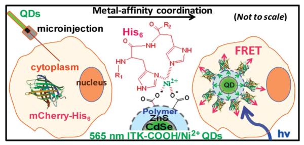
Schematic of a method to generate an intracellular QD-FP biosensor. Once injected into the cell, the Ni2+ containing QDs chelate the hexahistidine containing genetically expressed FP mCherry. FRET occurs between the QD donor and FP acceptor. Reprinted with permission from ref 390. Copyright 2010 American Chemical Society.
Cytotoxicity may occur when working with QDs due to their heavy metal content. Other types of nanoparticles that are capable of participating in FRET have recently been demonstrated for cellular studies. Sakka and co-workers developed a lanthanide-doped inorganic nanoparticle (CePO4:Tb)-small molecule (rhodamine) FRET pair.394 The lanthanide nanoparticles share many of the benefits of QDs (sharp Stokes shifted emission, resistance to photobleaching and also blinking), with a demonstrated low toxicity. FRET has been measured with the lanthanide-doped inorganic nanoparticle and a rhodamine acceptor in HeLa cells.
In summary, recent developments in FRET pairs for use in cells have solved many of the issues that exist when using FP-, small molecule- or nanoparticle-based FRET pairs. Further advancements in multiplexed FRET pairs will increase the number of cellular events that can be simultaneously measured to elucidate multi-step signaling pathways. New methods to site-specifically label biomolecules with small molecules and QDs, and routes to deliver FRET pairs to targeted cellular locations will also open new avenues in live cell FRET measurements.
3. Optical methods utilizing non-fluorescent nanoparticle probes
3.1 Non-fluorescent nanoparticle probes
Broadly speaking, the term nanoparticle encompasses any and all types of particles (single phase, hybrid, solid, core-shell, metallic, silica, diamond, etc.) with a diameter on the nanoscale. However, for the purposes of non-fluorescent single-cell imaging, noble metal nanoparticles stand apart as the most popular group of probes. The noble metals have retained their preeminence amongst researchers due to their stability, ease of synthesis, and optical properties. Silver and gold are the two most popular options, and they can be easily tailored to provide a strong optical signal in the visible or near-IR range.
The ideal nanoparticle for single-cell imaging would be composed of nominal mass in order to avoid any interruption of the processes within the cell and also provide a sufficiently intense signal for optical detection. At the current stage of research, nanoparticles on the scale of 10 – 100 nm have been found to work quite well for single-cell research. Particles below 10 nm in diameter are not as well-understood, because they are impacted by the quantum behavior of the conduction electrons, and they offer a much weaker signal.395 However, researchers are beginning to look at quantum-sized plasmonic nanoparticles more carefully, and particles within that size regime could prove valuable for single-cell imaging in the near future.
The optical properties of noble metal nanoparticles arise from a phenomenon known as localized surface plasmon resonance (LSPR).396 Briefly stated, when a nanoparticle is irradiated by light within a specific, narrow band of wavelengths, the vibrating electrical field around the nanoparticle displaces the electrons in the nanoparticle’s conduction band. Coulombic forces within the nanoparticle act to restore the electrons to their former positions, but as long as the illumination continues, the electrons in the particle will oscillate in phase and produce a signal that can be detected with the optical techniques discussed below. For a nanoparticle to produce a LSPR signal, it must be much smaller than the wavelength of light that it is being irradiated by.
In order to image noble metal nanoparticles, it is thus necessary to locate the band of wavelengths where the LSPR behavior will appear. Fortunately, the position of the LSPR is determined by several factors, the most important of which are the size and shape and composition of the nanoparticle. The surrounding dielectric environment (substrate and medium) can also produce a shift in the LSPR position.
The optical spectra of nanospheres can be determined by the application of Mie Theory, which is an exact solution of Maxwell’s equations for spherical particles.397-398 Spheres much smaller than the wavelength of light can be described even more simply by use of the quasi-static approximation to Mie Theory. Under this approximation, only dipolar contributions need to be considered when determining the cross sections for the sphere. The scattering (σsc) and absorption (σAbs) cross sections are thus given by:398-399
| (19) |
| (20) |
where λ is the illumination wavelength, a is particle radius, and m is the relative refractive index (the particle’s refractive index divided by the medium’s). The extinction cross section is merely the sum of the scattering and absorption cross sections. At small diameters, the extinction spectrum is dominated by absorption, but scattering grows in importance as the particle diameter increases.399-400 Because spheres are isotropic, they produce a single dipolar LSPR, but as sphere diameter increases, the LSPR red-shifts and undergoes broadening.398,401
The spectrum of a rod-shaped particle can be calculated exactly with the theory developed by Gans.396,402 According to Gans’ Theory, the absorption cross section is:402-404
| (21) |
where V is the rod’s volume, ε1 and ε2 are the particle’s complex dielectric constants, εm is the medium’s dielectric constant, and the polarization factors, Pi, and the factor, e, are defined as:
| (22) |
| (23) |
| (24) |
where L and T are the lengths of the particle’s longitudinal and transverse axes. Nanorods have two LSPR, one associated with each axis. The directionally dependent behavior of nanorods makes them a highly regarded probe for single-cell imaging. The position of the maximum longitudinal LSPR (in nm) can also be determined with:404
| (25) |
Although other nanoparticle shapes have been synthesized, they cannot be solved with exact methods as is the case for spheres or rods. Instead, their spectra can only be deduced by way of discrete dipole approximations (DDA) or other calculation-intensive methods.405 Another concern with imaging nanoparticles is being able to distinguish single, isolated nanoparticles from assorted aggregated conformations. While aggregates can display more complex behavior than single particles, they can be distinguished from single, isolated particles.406-410
More recently, researchers have turned an eye towards hybrid nanoparticles, which consist of a noble metal and a non-noble material or a combination of noble metals. Core-shell and multi-layered silver-gold nanoparticles have complicated spectra, instead of spectra that are linear combinations of the components.8,411-414 Magnetic metals can be added to a nanoparticle in order to provide for manipulation of the particle. However, magnetic materials alter and typically dampen the optical behavior of nanoparticles.8,398,415-416 Noble metal nanoparticles combined with semiconductors are capable of quenching or enhancing the fluorescence of the particle and could possibly serve as a sensor.8,417-418 The hybrid options are seemingly endless, but much research is still needed in that arena. For a more detailed description of alternative nanoparticle options, please refer to the recent extensive review by Cortie and McDonagh.8
A final topic that deserves consideration when selecting a nanoparticle probe for cell imaging is nanoparticle toxicity. Nanoparticles may present themselves as toxic due to the metal or semi-conductor material with which they are made. Alternatively, nanoparticles may be toxic as a result of their surface coatings. One reason for gold’s popularity is that gold itself is typically viewed as being non-toxic to cells. In comparison, QDs are considered to be quite toxic, regardless of surface coating. The collection of other nanoparticles that exist (e.g. silver, copper, mesoporous silica, carbon, iron oxides, etc.) are highly variable in their individual toxicities, thus toxicity should not be overlooked when designing a study. Nevertheless, further research into the toxicology of nanoparticles is certainly warranted, especially for such particles that are being designed for in vivo applications. Several detailed reviews and research papers have been written recently on this topic, and interested readers are encouraged to consider these other papers for more information on the subject.9-10,419-421
3.2 Optical methods for nanoparticle and single-cell imaging
Many of the experiments conducted for optical imaging of nanoparticles within single-cells rely upon commercially available microscopes. The focus of this section is on the theory of the more commonly-used instruments, with a brief discussion of key components and alternative instrument designs (Figure 11).
Figure 11.

Optical imaging techniques for non-fluorescent nanoparticles: (A) Dark field microscopy. (B) Photothermal. Reprinted with permission from ref 438. Copyright 2005 American Chemical Society. (C) Interferometric cross-polarization microscopy. BS, beam splitter; AOM, acoustic-optical modulator; GT, Glan Taylor polarizer. Reprinted with permission from ref 455. Copyright 2011 American Chemical Society. (D) Differential interference contrast (DIC) microscopy. The arrows show the vibration directions of the light beams at different locations.
3.2.1 Rayleigh scattering-based microscopy
Dark field microscopy is the most commonly utilized mode of microscopy for non-fluorescent nanoparticle detection. This technique relies on the collection of Rayleigh scattered light for image generation. Under conventional dark field microscopy, a specialized condenser is relied upon that prevents any light rays from passing directly through the condenser to the sample plane (i.e. the zeroth order light rays). As a result, only oblique rays of light are permitted through the condenser and interact with the sample. Because the N.A. of the objective is set to a lower value than that of the condenser, the oblique rays will fail to enter the objective in the absence of a sample, and the imaging field will appear dark. Light that is scattered by the sample can enter the objective, and it will appear as a white or colored feature against the dark background. However, cells are complex structures, and many of the surfaces within the cell can scatter light, thus creating a problem with large background noise and making nanoparticle detection a difficult challenge in some experiments.
Dark field microscopes are often coupled with additional components to aid with spectroscopy and nanoparticle detection. Since the sample is illuminated with white light, a monochromator or grating is often placed in front of the detector in order to provide a high resolution spectral profile of metal noble nanoparticles.422-424 In some experiments, filters (tunable or fixed) are preferred.408,425-426 When orientation information is needed from the nanoparticles, additional components can be added to the light path to provide the desired polarization setting.408,427 When a spectrometer is utilized, an additional option is to replace the spectrometer’s entrance slit with a liquid crystal device (LCD). This modification allows each pixel to act as an individual shutter with fast response, and as many as 20 isolated particles can be investigated at once using this technique.424,428
As an alternative to dark field microscopy, Louit et al., developed a confocal microscope that also collects Rayleigh scattered light.429 The system uses a tunable laser and filters to provide homogeneous illumination across the visible spectrum. Furthermore, the instrument provides sufficient time resolution for monitoring plasmon shifts as nanoparticles interact with cellular features. The technique also allows for the tracking of nanoparticles during endocytosis and exocytosis events.
3.2.2 Absorption-based microscopy
As shown above, the scattering signal of a nanoparticle drops off more quickly than the absorption signal with decreasing radius. Therefore, some researchers choose to work with absorption-based spectroscopy. The simplest absorption technique is bright field microscopy. For this method, light is transmitted directly through the condenser and the sample plane. As a result, nanoparticles and other features that absorb light appear to be dark upon a bright background. When video-enhancement became available in the 1980s, researchers were finally able to track small gold nanoparticles (≥15 nm) to research on endocytosis and lateral protein motions on cell exteriors.430 Bright field is still used by researchers today for cell and nanoparticle imaging, but it is typically used to complement other imaging techniques.431-432
A second absorption-based microscopy is spatial modulation spectroscopy (SMS). This technique measures nanoparticle absorption by moving the particle in and out of the focal plane.433-434 Although this technique can detect particles as small as 5 nm, the nanoparticles must be fixed to a surface. As such, it has not been utilized for biological studies to date.
A third method, photothermal heterodyne imaging (PHI), utilizes a dual laser beam configuration to detect a nanoparticle by way of a thermal lens that is created by the pump laser.434-437 Nanoparticles absorb energy from a time-modulated excitation laser and convert the energy into heat. Subsequently, as the heat is dissipated from the nanoparticle, the surrounding medium undergoes a time-modulated variation in its refractive index. The non-resonant probe beam interacts with the modulating medium and produces a scattered field. By using the probe beam’s beatnote to monitor the scattered field, gold nanoparticles as small as 1.4 nm can been detected. However, the technique’s sensitivity is closely linked to the fluid surrounding the nanoparticle.437 Additionally, PHI can be used to detect noble metal or semiconductor nanoparticles, and it can detect the orientation of a nanoparticle when polarized light is utilized.434,438
When PHI is coupled to a piezoscanner stage for raster scanning of the sample, the technique is referred to as Laser Induced Scattering around a NanoAbsorber (LISNA).435 LISNA has been used with live cell imaging at video rate for several minutes at a time, but because it is a raster scanning technique, it is somewhat limited to slower biological processes. As such, few PHI experiments with this design have been conducted. Instead, recent PHI experiments have tracked dynamic nanoparticles by focusing multiple laser beams at fixed locations within the cell to detect time fluctuations in the photothermal signal.439
3.2.3 Photoacoustic methods
Photoacoustic tomography (PAT) is a specialized absorption technique that effectively combines optical and ultrasonic imaging, thereby providing a means of noninvasively imaging tissues.440-444 As a result, it provides deeper imaging than other optical techniques while avoiding radiation and the high costs associated with diagnostic, molecular imaging.444 Moreover, a wide variety of nanoparticles can be used as functionalized probes for use with PAT, including gold, copper, magnetic materials, and QDs.441,443-446 By functionalizing the nanoparticles, it is possible to target and detect specific types of cells within tissue, such as cancerous cells.
PAT produces a high-contrast image of tissues and molecular contrast agents (e.g. nanoparticle probes) that absorb sufficient radiation.441 To produce the image, a short-pulse laser beam first irradiates the sample, typically in the near-infrared range. As tissues absorb the incoming radiation, they undergo thermoelastic expansion and re-radiate the energy in the form of photoacoustic waves. A transducer is responsible for detecting the photoacoustic signals.
PAT can be split into two distinct modes based on how the transducer collects the signal.447 If the transducer raster scans the sample, the mode is referred to as focused scanning tomography. This mode includes photoacoustic microscopy (PAM) and confocal dark field PAM. The time to complete a scan is dependent on the laser pulse rate, the step size of the scan, and the size of the area being scanned.442 Alternatively, an array of transducers can be used in parallel for detection, in which case the mode is referred to as photoacoustic computed tomography. Under this mode, frame rates as high as ~50 MHz can be achieved.
The maximum penetration depth attainable with PAT is ~30 mm in biological tissue, but the actual depth is dependent upon the ultrasonic frequency used by the transducer.444 Furthermore, as penetration depth is increased, axial and transverse resolution is drastically reduced. At a depth of ~3 mm with the transducer set to 50 MHz, PAT provides an axial and transverse resolution of 15 and 45 μm, respectively.
More recently, efforts have been made to match PAM’s lateral resolution to that of optical methods. In one such case, the sample is doubly illuminated from the top and bottom, simultaneously.448 However, the penetration depth is limited to ~2 mm in tissue at a wavelength of 532 nm. In another variation known as pure optical PAM (POPAM), weak photoacoustic signals are detected by means of a focused excitation beam and a specialized micro-ring resonator with a broad bandwidth for signal detection.449 This technique has been capable of providing a lateral and axial resolution of 5 and 8 μm, respectively.
3.2.4 Interference-based microscopy
An alternative method for detecting nanoparticles is interferometry. This method is capable of distinguishing nanoparticles from its background, because it exploits the interference of the background reflection with the nanoparticle-induced scatter. Thus, the normalized cross-section for the images seen under this method is described by:450-451
| (26) |
where
| (27) |
and Im is the measured intensity of a particle at the center of the focus as a function of the particle diameter (d), Ir is the average measured intensity of the reflected light in the absence of the particle, Ei is the electric field at the particle’s location, Er is the electric field of the background illumination, Es is the electric field of light scattered by the particle, r is field reflectivity, s is the complex scattering amplitude, and φ is the phase of the scattering. The three terms on the right-side of Equation 27 represent the background intensity, the purely scattered intensity that scales as d6, and the cross-term that scales as d3. For very small particles, the second term becomes smaller than the noise observed with the first term, while the third term becomes the dominant factor.
A standard homodyne instrument setup utilizes a low powered (≤10 mW) laser for illumination on a commercial microscope.451 Either white or monochromatic light can be used to illuminate the sample. A piezo stage is utilized for scanning the sample area. The reflected signal is collected by a photomultiplier with a low-noise current-voltage amplifier. Because of the destructive interference between scattered and reflected light, small particles appear to be dark against the background. Using this instrument design, 5 and 10 nm gold nanoparticles at a water-glass interface were detected at an integration time of 2 and 1 μs, respectively under confocal microscopy. However, a limitation of this design is that the phase must be known in order to elucidate the electric field scattered by the particle.452
More recently, heterodyne and phase-shifting interferometers have been designed, and they are capable of independently measuring the amplitude and phase of the scattered field.452-454 Under heterodyne interferometry, the signal is allowed to interfere with a frequency-shifted reference beam, thereby producing a beat frequency. The signal is demodulated at the beat frequency, resulting in a decoupled phase and amplitude. Simple dual-phase interferometers can even be scaled down to a portable unit for forensic and biodefense applications.452 When heterodyne interferometry is combined with dark field microscopy, the background noise is reduced, and ~48 nm diameter viruses and bacteriophages have been detected label-free in solution in real-time.453 Under phase-shifting interferometry, known phase shifts are introduced.452 By taking independent measurements of the signal intensity in sequence or simultaneously, it is possible to determine the scattering by the particle. With this design, immobilized 25 nm gold particles have been detected at 1 ms in water.452
Heterodyne interferometry can also be combined with cross-polarization microscopy.455 In such a design, linear polarized light is sent through a beamsplitter to create a signal and a reference beam that are x- and y-polarized, respectively. A high NA objective along the signal beam induces a partial conversion of x polarized light into y-polarization. An objective collects any y-polarized scattering that occurs by objects in the signal beam path. By then overlapping the two beams, only y-polarized components of the electric fields will interfere, and as a result, the background is shot-noise limited. Particles thus appear as a cross-polarized object with white and black spots upon a black or dark gray background. This design has been able to detect gold nanospheres on a glass slide as small as 5 nm at an excitation power of ~1 μW.
3.2.5 Differential interference contrast microscopy
Differential interference contrast (DIC) microscopy is a specialized variation of interferometry. Nomarski DIC is the primary microscope design for imaging in the visible and near-IR range, and it is also commercially available. Other variations of DIC microscopy do exist, but they are either used for X-ray imaging, or they have not proven as popular as Nomarski DIC.456-457 Nomarski DIC’s popularity largely stems from its reliance on a large condenser aperture, which provides a higher lateral resolution and a shallower depth of field than either dark field or bright field microscopy.457-459 As a result, DIC provides sharper cell images than dark field or bright field, because it doesn’t suffer from out-of-plane scattering or absorption.459
In addition to a condenser and objective, the main components along the light path of a Nomarski DIC microscope consist of two birefringent Nomarski prisms, a polarizer, and an analyzer.408,457,460-461 Non-polarized white light passes through the polarizer and then undergoes shearing into two orthogonal beams at the first prism. Resultantly, two coherent beams with a lateral shear of ~100 – 200 nm pass through the condenser and illuminate the sample plane. Both beams are also at a 45° angle relative to the polarizer. After being gathered by the objective, the two orthogonal beams are recombined by the second prism before passing through the analyzer on its way to the detector. Filters are usually placed in the light path to collect images at specified wavelengths, since it isn’t trivial to introduce a spectrophotometer to the light path due to DIC’s reliance on the principles of interferometry. To perform rotational studies, a rotating stage is also preferred.408
Nanoparticles and other features that introduce a phase shift to either of the two sheared beams will appear as a shadow-cast object on a gray background in a DIC image.408,461-463 At the LSPR wavelength(s), the shadow-cast appearance of an isotropic nanoparticle will not change with rotation of the object in relation to the polarizer, because the particle remains equally aligned with both of the sheared beams at all orientations. However, an anisotropic nanoparticle can appear as predominantly white, predominantly black, or as shadow-cast, depending on the orientation of the LSPR axis with the two orthogonally sheared beams. In fact, for gold nanorods with a LSPR in the visible range, the relative intensities of the black and white signal oscillate according to a cos4 and sin4 relationship, respectively.462 By monitoring the changes to the two signal components, it is possible to discern the 2D and 3D orientation of a nanorod, even if it is in motion.
Image quality and nanoparticle contrast can be adjusted by introducing an intentional phase shift to the wave train. To introduce a phase shift, traditional Nomarski DIC microscopes rely on translating the condenser-side prism while the objective-side prism remains fixed. Modern de Sénarmont-Nomarski DIC microscopes employ a birefringent quarter wavelength retardation plate (QWRP) in the light path before the condenser. While the fast axis of the QWRP is fixed at a 90° angle to the analyzer, the polarizer is rotated to adjust the phase shift between the two beams. Researchers must take care in selecting an intentional phase shift, however, particularly when working with a gold nanorod sample that displays lots of polydispersity in the LSPR position. Adjusting the phase shift alters the optical behavior of gold nanorods at non-plasmonic wavelengths.460
Nomarski DIC has already been proven to be effective at cell research. For example, DIC has been used to observe nanorods rotating on a live cell membrane at 200 frames/s,464 and elucidate the rotational dynamics of cargos at pauses during axonal transport in neurons at 500 frames/s.465 Because DIC is non-intrusive and does not require staining, as fluorescence microscopy does, DIC can be used for monitoring cells and nanoparticles over extended periods of time.466 As such, DIC has been utilized to track nanoparticles undergoing endocytosis and transport through cells, which is discussed in further detail in Section 5.461-462,464
3.2.6 Second-harmonic generation imaging
Second harmonic generation (SHG) is a nonlinear optical process, in which the high-flux of photons interacting with a nonlinear optical material are combined to form new photons with twice the frequency (half the wavelength) of the incident photons. The intensity of SHG signal is proportional to the square of the incident laser intensity. Thus, SHG imaging (SHGI), similar to MPEF imaging, allows for detection in the visible region upon IR illumination, and offers excellent axial sectioning capability and lateral resolution comparable to that of confocal fluorescence microscopy without having to use a pinhole.
In contrast to MPE processes, SHG is a coherent scattering process. It does not involve excited molecular states, although the SHG signal can be enhanced upon resonance. The majority of SHG signal can be detected in the propagation direction of the incident laser beam. SHGI systems usually adopt a trans-detection scheme. However, in case of thick or scattering media, back scattered signal can also be detected even though it is weak. For biological samples, SHGI has two advantages over MPEF imaging. First, photobleaching is normally low in SHGI compared to MPEF microscopy. Second, many ordered endogenous structures in cell/tissue, e.g., collagen, actomyosin complexes, tubulin, etc., can give strong SHG signals and allow for label-free imaging.467
Recent development in SHG imaging instrumentation
Since the demonstration of the first SHG microscope in biological research by Freund et al.,468 followed by further contributions from several other groups,467,469-470 SHGI has now become a very useful tool for bio-imaging. Advances in laser technology, scanning approaches, exogenous probes, and labeling procedures have led to SHGI’s applications not only in fundamental research but also in clinical diagnostics.467,471-472 SHGI techniques are similar to those based on confocal and MPEF by nature. Recent development in SHGI in live cells includes multifocal SHGI for faster imaging speed121 and multimodal imaging that allows simultaneous measurement of SHG and 2PEF signals from the same optical setup.123-124,473-474 Multimodal imaging provides an opportunity to compare the two images that are obtained from two entirely different quantum processes, providing rich information for the study of various biological processes.
Exogenous SHG probes
Although many ordered structures in cells and tissue can produce inherent SHG signal, exogenous probes are frequently used to increase the contrast or to selectively image non-signal targets. These exogenous probes mostly target the lipid bilayer in cells. A nice review of SHG dyes can be found in a recent review article by Reeve et al.475 A current issue with SHG dyes is their photo-bleaching. Development of novel probes that are less prone to bleaching and blinking while maintaining strong SHG signal is an active area of research.476-483 For example, Pantazis et al. have shown that BaTiO3 nanocrystals are photostable SHG probes.484 Reeve et al. have synthesized amphiphilic porphyrins that are capable of yielding strong SHG signals and are also more resistant to photo-bleaching than other SHG dyes.485
Because SHG requires a non-zero second harmonic coefficient, only non-centrosymmetric structures are able to emit SHG light. The molecular SHG probes must align spatially in the targeted area in order to generate SHG signal. Membrane-targeting probes, e.g., fluorescent calcium indicators or voltage-sensitive fluorescent probes, usually self-align due to the unique scaffold provided by the cell membrane and give an excellent signal.486-492 Because the SHG signal intensity is sensitive to changes in transmembrane cell potential, Campagnola et al. used SHGI to determine changes in membrane potential in lymphocytes labeled with a voltage sensitive dye.467,493 In recent years, SHGI, similar to MPEF imaging, has been extensively used for imaging ordered structures at live tissue/organs level, e.g., cornea494 and lamina cribrosa sclerae.495 These studies, although important, do not fit into the scope of this review.
4. Raman imaging
Raman spectroscopy is an inherently label-free, non-destructive, non-invasive vibrational technique that provides information about the chemical content of a sample. There are many variants of Raman techniques including surface enhanced,496 resonance,497 tip-enhanced,498 total internal reflection499-500 and coherent anti-stokes501 Raman spectroscopies. While Raman spectroscopy is complementary to infrared spectroscopy, it has several properties that make it a better choice for many single cell analyses. Raman spectra often exhibit narrow spectral peaks compared to fluorescence and infrared spectroscopies, so it may be possible to measure distinct chemical species even in the complex cellular environment. Narrow spectral peaks are also desirable for multiplexed assays. Unlike infrared spectroscopy, Raman spectroscopy is well-suited for measurements in aqueous environments since excitation wavelengths are below 1300 nm, where the onset of water adsorption occurs.
4.1 Surface enhanced Raman spectroscopy (SERS): Recent developments in SERS substrates and applications to single cell analysis
Non-enhanced or conventional Raman spectroscopy is a low signal technique compared to many other molecular spectroscopies. Typical Raman cross-sections of molecules are on the order of ~10−30 cm−2, while fluorescence and infrared cross sections are several orders of magnitude larger.502 However, Raman scatter can be enhanced by up to ~14 orders of magnitude when the Raman scatterer is in close proximity to a SERS substrate.502-503 There are two mechanisms for this enhancement: electromagnetic and chemical, which are discussed in detail elsewhere.504-506 The SERS enhancement enables detection limits that parallel fluorescence spectroscopy, down to the single molecule level.502,507-508 Short acquisition times and low laser powers can often be used for SERS as a result of the signal enhancement,509 and these conditions are favorable for live cell analyses. On the other hand, these benefits typically have to be weighed against the use of exogenous SERS substrates.
The SERS substrate is critical for a successful experiment, and many variants will be described below. One common feature is noble metal substrates with roughness on the order of the wavelength of light. Although several plasmonic materials can be used as SERS substrates, Au and Ag are the most common due to good chemical stability and large SERS enhancements, respectively.510 Both solution-phase and surface-confined nanoparticle arrays can be used. Intracellular measurements usually require the delivery of nanoparticles from solution across the cell membrane since the SERS signal is generated only from molecules within a few nanometers from the SERS substrate. Surface-confined nanoparticles are suitable for measuring cell membranes and other extracellular species.
SERS has become an important tool for intracellular and extracellular measurements of chemical content. Several published reviews cover single cell applications of SERS.18,511-516 Similar to other promising single cell analysis techniques, SERS has areas that can be improved. Careful attention must be paid to the selection of a SERS substrate for a particular application to avoid issues of low signal enhancement, poor selectivity, irreproducible signals and poor intracellular delivery to the desired cellular locations. Unlike fluorescence-based measurements where genetic approaches to specifically label a target species are in common use, SERS substrates are primarily exogenous (although intracellular synthesis routes are being pursued).517 Exogenous SERS substrates can be incorporated into the cell using cellular uptake, electroporation, nanoinjection and similar mechanisms.518-521
In SERS experiments, any molecules within a few nanometers of the SERS substrate can generate SERS signal. The complex intracellular environments can lead to the enhancement of unwanted signals from numerous cellular components that make the vibrational spectra difficult to interpret. Many of the recent developments in novel SERS substrates for cellular applications address these issues; many of these are proof of concept studies. The advancements in SERS substrates that have been applied to single cell analyses from the past two years will be covered in this section. Also select applications of SERS for the cellular detection of small molecules and cancer cells will be discussed. Excluded from the section are applications of SERS to whole tissues,522 microorganism detection and discrimination,523-526 and all non-biological applications.527
4.1.1 SERS substrates: nanoparticle uptake, tracking, stability and functionalization
The first SERS study of endocytosed Au nanoparticles was performed to image an anti-cancer drug in a live cell.528 Since this first report in 1991, exogenous SERS substrates have been shown to be exceedingly dependent on the substrate uptake efficiency and localization. Important SERS substrate properties include the size, shape, and surface functionality and charge. Nanoprobes or nanosensors are SERS substrates composed of a nanoparticle functionalized with a small molecule that has a large Raman cross section, known as a Raman reporter. Matschulat et al. demonstrated multiplexing applications of the nontoxic SERS nanoprobes in high density sensing and imaging in complex biological structures.529 The work of Vo-Dinh et al. demonstrated the uptake efficiency of positively, negatively or neutrally charged nanoprobes in single cells with SERS imaging.530 The positively charged 4-aminothiophenol-labeled nanoparticles and negatively charged 4-mercaptobenzoic acid-labeled nanoparticles were taken up more readily by the cells than neutrally charged 4-thiocresol-labeled nanoparticles. The SERS spectra from three cellular locations in a macrophage cell are shown in Figure 12A and the cellular distribution of 4-aminothiophenol labeled Ag nanoparticles measured with SERS tracking is shown in Figure 12B. The study shows the importance of surface charge on nanoprobe uptake efficiency and stable internalization for long term observations, and can lead to advancements in the controlled delivery of exogenous SERS substrates.
Figure 12.

Monitoring the uptake of positive, negative, and neutrally charged SERS nanoprobes. (A) SERS spectra of 4-aminothiophenol sampled over three different locations in a macrophage cell. (B) Cellular distribution of the negatively charged 4-aminothiophenol labeled Ag nanoparticles in macrophage cells using SERS mapping. Reprinted with permission from ref 530. Copyright 2011 Elsevier.
The stability of nanoprobes within physiologically-relevant environments including the cell culture media and the intracellular matrix has been recently studied by Cooper et al.531 Their results show SERS probes containing a chemisorbed Raman reporter (e.g., 4-mercaptobenzoic acid, 4-mercaptopyridine) on Ag nanoparticles has a stable signal inside cells for up to 24 hours, while Raman scatter from a physisorbed reporter (e.g., crystal violet, rhodamine 6G) decreased over the course of several hours. Similarly, Campbell et al. used chemisorbed 4-mercaptobenzoic acid on Au nanoshells for intracellular sensing in NIH-3T3 fibroblast cells.532 The functionalized nanoshell substrates were internalized to the cytosol through the cell’s natural uptake mechanisms, and the SERS enhancements were on the order of 1010 higher compared to conventional Raman measurements that didn’t utilize a SERS substrate. Another functionalized SERS substrate used alkynes as an alternative to thiol-based ligands. Pezacki et al. used alkynes to form carbon-bound Ag nanoparticles for SERS imaging of human hepatoma Huh7.5 cells.533 The alkynes produced stable nanoparticles in aqueous environments, strong SERS signals and can contain electrophilic functional groups that are incompatible with the more traditional thiolate ligands.
In order to selectively target specific components in the complex cellular environment, nanoparticles can be functionalized with chemical receptors such as peptides. Recently, Hu and co-workers reported a SV-40 large T nuclear localized signal peptide-functionalized Au nanoparticle that enabled measuring chemical content from the nucleus of single HeLa cells.534 The nuclear localization signal peptide targeted the cell nucleus without interfering Raman peaks arising from the functionalization. In other SERS experiments targeting the nucleus, Gregas et al. developed a co-functionalized SERS substrate with a nuclear targeting peptide and SERS reporter attached to a Ag nanoparticle.535 The platform allowed detection and tracking of particle uptake efficiency and localization in the nucleus with two-dimensional SERS imaging. Results show functionalization with the nuclear targeting peptide enhances uptake efficiency into the cell nucleus relative to particles without a penetrating/nuclear localization peptide.
One way to enhance signal reproducibility is to employ a SERS substrate with a fixed spatial arrangement. SERS nanopipettes have been used for in situ intracellular measurements of isolated intact HeLa human cervical carcinoma cells.536 Gogotsi et al. fabricated a nanopipette composed of a polylysine-functionalized glass capillary with a 100- to 500-nm tip coated with Au nanoparticles. The positioning of the nanopipette over the cell nucleus and cytoplasm could be distinguished in HeLa cells based on the Raman spectrum. The nanopipette can be used to monitor real-time intracellular biochemical processes. This was demonstrated by monitoring time resolved Raman spectra of HeLa cells after potassium chloride treatments. Further optimization of the technique could enable identification of organelles near the nanopipette and quantitative measurements of biomolecules.
Carbon nanotubes have been commonly used for cellular probes, but have not traditionally been used for single cell SERS measurements.537 Niu et al. developed a carbon nanotube-tipped endoscope as an alternative substrate to avoid nanoparticle aggregation.537 The 200-nm carbon nanotubes were decorated with 20-nm Au nanoparticles to study intracellular environments in situ. One important feature of the carbon nanotube endoscope is the ability to enter the nucleus and allow distinction between healthy, diseased, or contaminated cells. The uniform attachment of the Au nanoparticles allowed for highly sensitive measurements of the amino acid glycine down to picomolar concentrations with good reproducibility.
The alignment of Au-coated carbon nanotube arrays with respect to the incident laser beam has recently been reported by Lu et al. to be a significant factor in multi-walled carbon nanotube SERS enhancements.538 Carbon nanotubes that were oriented parallel to the polarization of the incident beam had significantly larger enhancements than carbon nanotubes that were oriented perpendicular and demonstrated a detection limit of deuterated and 13C-labeled fatty acids on the nanomolar level. The carbon nanotube SERS substrate was also used to measure a strain of microalgae cells to demonstrate the biological effectiveness of the SERS substrate.
Chen and co-workers compared the normal Raman and SERS signals of intracellularly-grown and passively-uptaken Au nanoparticles in nasopharyngeal carcinoma cells.517 More Raman bands could be assigned in the SERS spectra than the normal Raman spectrum of the cells. While the locations of many peaks in the spectra were the same for the intracellularly grown and passively uptaken SERS spectra, the intensities of the peaks were quite different across the two spectra. It is possible that this represents the natural variability from cell to cell, or as hypothesized by the authors that the two SERS substrates localized differently within the cell.
Proteins, lipids and small molecules in the cell membrane can be labeled with nanoparticles. An immunolabeling protocol with Au-conjugated antibodies coupled with Ag nanoparticles for obtaining unique biomolecular information of the cellular surface was developed by Hodges et al.539 The advantages of this method include better detection limits than conventional light microscopy for detecting Au nanoparticles combined with the ability to perform spectral imaging of cell membrane components.
4.1.2 SERS substrates: nanostars, flowers, clusters, and assemblies
Multi-branched nanoparticles such as nanostars, nanocubes and nanoflowers is an active area of interest in single cell SERS measurements due to their strong plasmon resonances in the near-infrared region (NIR) and ability to generate “hot spots” due to their sharp morphologies.540-541 SERS-encoded Au star-shaped substrates have been fabricated by Brust et al. and used for intracellular SERS imaging.542 SERS images of HeLa cells were acquired with 830-nm NIR excitation. The optical properties of the star-shaped nanoparticles in comparison to spherical shaped nanoparticles are optimum for near-infrared excitation, wavelengths that are favored to limit cell damage, and enable the Raman images to be acquired in less time.
When using multi-branched nanoparticles internalization efficiencies up to three-fold lower than spherical shaped nanoparticles may be encountered.542 One way to improve the internalization, biocompatibility and systemic retention is to encapsulate the nanoparticles with a non-toxic hydrophilic polymer.543 Recently this was done by Astilean and co-workers with a novel synthesis method for flower-shaped Au nanoparticles functionalized with a thiol-modified poly(ethylene) glycol (PEG) polymer.544 Intracellular detection with the multi-branched flower-shaped nanoparticles was successfully tested in the cytosol of human epithelial cells with two Raman reporters: the dyes malachite green oxalate and basic fuchsin. Overall, the SERS substrate showed low toxicity and produced high signal enhancements. The PEGylated coating on the flower shaped nanoparticle can further be conjugated with specific ligands for SERS imaging and detection of cancerous cells.
SERS activity is also affected by the geometrical configuration of the SERS substrate. In a recent development, Xu et al. used regiospecific plasmonic nanoscale-superstructures that were assembled using DNA oligomers.545 The regiospecific nanostructures display a new level of control over the placement of nanoparticles, which can lead to structures with optimal SERS enhancements. Specific assemblies (i.e., nanorod surrounded by nanospheres) can penetrate through the HeLa cell membrane and enter the cytoplasm. They displayed adequate signal enhancement to detect lipids and potentially small molecule metabolites. These nanoprobes have the potential to be used in real-time monitoring of metabolic processes within single cells.
4.1.3 Detection of small molecules
Over the past few years SERS has become a useful tool for monitoring drug delivery inside cells. A novel method reported by Wang et al. used Ag nanoparticles that were pre-internalized in living HeLa cells to detect the diffusion of 6-mercaptopurine and methimazole inside a living cell.546 Metabolism rates in HeLa cells for the two drugs was monitored with a detection limit of 1 nM for 6-mercaptopurine in a single HeLa cell, demonstrating that the higher background sometimes associated with SERS did not preclude measurements of compounds at physiologically relevant concentrations. Mixtures of drugs inside living cells along with kinetics and diffusion can be monitored using the pre-internalized nanoparticles. In further studies to monitor drug release, Lee et al. investigated in vitro and in vivo glutathione (GSH)-induced intracellular thiopurine anticancer drug release from Au nanoparticles.547 Monitoring 6-mercaptopurine and 6-thioguanine was performed with SERS in real time with drug detection limits in the nanomolar regime. These studies demonstrate SERS’ ability to chemically target and track species in complex environments.
Fiber optic sensors for single cell SERS analysis can be ideal nanoprobes for in vivo measurements of single cells.548 Recently, SERS and fiber optic sensors were combined to make a submicron-sized nanoprobe to measure intracellular pH of a human mammary epithelial cell line and a human prostate cancer cell line.549 The intracellular pH of both cell lines was determined to be ~7.3, which is in the expected range for healthy cells. The fiber optic probe was physically inserted into the cells using micromanipulators and seemingly did not cause significant environmental stress while being able to capture high signal-to-noise ratio Raman spectra with 10 second exposure times and ~35 mW of laser power. One drawback to fiber-optic probes, glass pipettes or nanopipettes is their rigid structure and relatively large sizes with respect to cell dimensions, which can cause physical damage to the cells when used for in situ measurements.18
4.1.4 Detection of cancer cells and treatment efficacy
There is considerable interest in developing Raman-based methods to diagnosis cancerous cells and tissues and to monitor the efficacy of cancer therapies. Many of the strategies that have been developed to date use SERS substrates that contain a peptide or protein to target a specific cellular marker, often on the cell membrane, that is unique to cancer cells or has a differential expression in cancerous cells.522,550-554 Moskovits and co-workers developed one such strategy for distinguishing cancerous epithelium prostate cells from non-cancerous cells.551 Their approach was to ratio the signal obtained from two separate Ag nanoparticle-based SERS substrates to detect the over expression of neuropilin-1 in the cancerous cell line. One substrate contained a peptide that bound to neuropilin-1 receptor on the cell membrane and a small molecule thionin Raman reporter. The other substrate contained a control cell penetrating peptide and a methylene blue Raman reporter. The excitation wavelength was in resonance with the Raman reporters. They were able to specifically detect the cancerous cells by analyzing and ratioing the signal that originated from the two different reporter molecules. The authors reported that this ratiometric approach overcomes the complications originating from differences in the focal plane, cell concentration and turbidity when imaging cell samples. Polymers and lipids have also been utilized as nanoparticle coatings for targeting cancer cells.555-556
SERS substrates have been used to monitor/increase the efficacy of therapeutic strategies.557-559 Liu et al. have developed a multi-step synthesis to make single wall carbon nanotubes coated with noble metal nanoparticles, polyethylene glycol and folic acid to target folic acid receptor positive cells.558 The nanoparticles act as both a SERS substrate and increase the efficacy of photothermal therapy used to ablate cancer cells. High SERS signals were recorded for the folic acid receptor containing human epidermal carcinoma cell line, but were low for the folic acid negative HeLa cell line. Overall, the nanoparticles were non-toxic in the absence of the photothermal therapy, but decreased the viability of the targeted cell line after treatment and reduced SERS imaging times from ~1 second per pixel to 0.1 second per pixel.
4.1.5 SERS-active substrates: dual imaging mode probes
SERS has been combined with other analytical techniques such as microfluidics, flow cytometry, fluorescence and surface plasmon resonance.560-568 SERS substrates that can act as multimodal imaging probes have been developed to target specific cancer cell lines or markers.569-571 He et al. showed that Au nanorod SERS substrates could be used for dual dark-field and SERS imaging.569 The nanorods had a Raman reporter, a polyelectrolyte coating, and finally ligands for commonly over expressed receptors on tumors (i.e., carcinoembryonic antibody or transferrin) physisorbed to the polymer coating. Dark-field imaging revealed the presence of the nanorods on HeLa cells, while the SERS imaging provided the unique Raman signal for the reporter. Thus, the SERS signal could be used for multiplexed studies to measure, for example, the expression of multiple cell surface receptors simultaneously.
A new approach recently published combined SERS with particle tracking.572 This approach not only provides the vibrational information from SERS but also the particle trajectory within the cell with sub-diffraction spatial resolution. 50-nm Au nanoparticles served as a SERS probe traveling within the cell and reporting the biochemical composition along its path. A combination laser-beam scanning Raman and dark-field microscope with feedback kept the beam centered on the moving nanoparticle. The molecular map of organelle transport and lysosomal accumulation were detected with 65-nm spatial resolution and 50-ms temporal resolution. Time resolved SERS spectra obtained with a nanoparticle traveling through a macrophage cells is shown in Figure 13A. The schematic showing the relative movement of the nanoparticle while passing by intracellular molecules is shown in Figure 13B with a linear trajectory model of the Au nanoparticle shown in Figure 13C. This technique can capture SERS images of specific dynamic biological functions including membrane protein diffusion. Others have also combined SERS with dark field microscopy to provide information on the intracellular uptake mechanisms and location in a single mammalian cell.573
Figure 13.

Dynamic SERS imaging inside a living cell can provide local molecular information over microsecond intervals. (a) High temporal resolution Raman spectra collected at 50 ms intervals. The stationary peaks indicate the nanoparticle had prolonged interaction with the molecule and peaks appearing and disappearing indicate molecules short residence times. (b) Schematic of the nanoparticle with molecules passing by and molecules with prolonged interactions. (c) Example linear trajectory of a Au nanoparticle acquired during a dynamic SERS imaging experiment. Reprinted with permission from ref 572. Copyright 2011 American Chemical Society.
Itoh and co-workers used a combination of plasmon resonance Rayleigh scattering (PRRS) and SERS with Ag nanoparticles to measure mannoproteins on yeast cell walls.574 PRRS imaging can achieve single nanoparticle detection levels, while SERS can distinguish Rayleigh scattering from the nanoparticles and other components of the cell. While a beneficial technique, it requires improvements to obtain more reproducible SERS measurements and increase both spectral and temporal resolution.
Kang et al. combined dark-field Rayleigh scatter imaging and confocal Raman microscopy for investigating different phases of a single cell during a full cell cycle.575 The technique has the capabilities to monitor any target cellular component during the full cell cycle using functionalized plasmonic nanoparticles. The technique is currently being investigated to determine if vibrational information from the cellular component can predict cell heath throughout the cell cycle process.
In summary, recent SERS developments leverage the inherent signal enhancement while improving signal specificity and reproducibility. Further advancements in new routes to intracellular delivery and synthesis of nanoparticles without loss of cell viability will expand the utility and application of SERS for single cell analyses. The novel SERS substrates reported in this review could lead to the real time analysis of proteins, metabolic rates and drug delivery in living cells with chemical specificity.
4.2 Single cell analysis by coherent Raman scattering microscopy
Coherent Raman scattering (CRS) microscopy is a recently developed label-free, noninvasive imaging technique.576-577 CRS microscopy can detect targeted molecules in a complex biology system with chemical selectivity by matching the vibration frequencies of specific chemical bonds.578-579 CRS microscopy exhibits several unique advantages for the study of biological systems. First of all, contrast of CRS microscopy is based on intrinsic molecular vibrations, thus eliminating the need for labeling and circumventing possible perturbation to the system caused by exogenous dyes.578,580 Second, signals of CRS microscopy are produced by nonlinear optical processes, rendering submicron spatial resolution and intrinsic three-dimensional sectioning.578-579,581 Third, CRS microscopy is minimally invasive to biological samples, because high contrast can be achieved by moderate laser powers.581-582 By virtue of these properties, CRS microscopy is suitable for biological studies on living cells, tissues or organisms.581-583 CRS microscopy is a growing family of the Raman scattering based imaging techniques, with coherent anti-Stokes Raman scattering (CARS),580,584 stimulated Raman scattering (SRS)585-587 modalities (Figure 15A) and their variants, including polarized CARS,588 multiplex CARS589-593 and multi-wavelength SRS,594 compound Raman spectromicroscopy,595 hyperspectral CARS596-597 and hyperspectral SRS.598 Developments in CRS microscopy have offered new opportunities for researchers in biology, pharmacy, chemistry and other fields. Extensive applications of CRS microscopy to these other fields have been covered in several recent reviews.578,581-583,599-603 In this section, instrumental developments and applications of CRS microscopy to single cell analysis will be discussed. The applications include: understanding the biology of lipid storage and metabolism, monitoring cell growth and differentiation, demyelination and remyelination on a single axon, visualizing the processes of cell mitosis and apoptosis, and measuring cellular uptake of nanoparticles or drugs.
Figure 15.

(A) Energy diagrams of SRS and CARS. (B) SRL imaging of deuterated palmitic acid-d31 in live CHO cells at CD stretch vibration and CH stretch vibration, respectively. Reprinted with permission from ref 587. Copyright 2011 American Chemical Society. (C) Simultaneous CARS imaging of axonal myelin (red) and TPEF imaging of Oregon green 488 (green). Reprinted with permission from ref 630. Copyright 2005 Biophysical Society. (D) SRS images of nucleic acids at 785 cm−1 in a salivary gland cell from Drosophila melanogaster, via the stimulated Raman loss detection scheme. Reprinted with permission from ref 640. Copyright 2012 WILEY-VCH Verlag GmbH & Co. KGaA, Weinheim. (E) CARS imaging of cellular uptake of 200-nm polystyrene nanoparticles encapsulated in folate-targeted liposomes (red) in KB cell. Reprinted with permission from ref 641. Copyright 2007 American Chemical Society. Scale bar: 10 μm.
4.2.1 Instrumental developments
By offering chemical selectivity without labeling, vibrational microscopy opens numerous opportunities for applications in biological research. Spontaneous Raman spectroscopy and microscopy have been extensively used in many research areas, like material identification, cancer diagnosis, and monitoring of cellular metabolic changes.578,601 However, due to the very small cross section of Raman scattering, spontaneous Raman imaging takes a long acquisition time, thereby limiting the applications of Raman microscopy to living cell studies.578 Low signal level of spontaneous Raman microscopy can be overcome by enhanced Raman scattering techniques, such as SERS508,604 or CRS microscopy.601 SERS can achieve near-single molecule sensitivity, but requires a proper exogenous substrate.508 On the other hand, CRS microscopy can achieve several orders of magnitude higher signal level578,599 than Raman microscopy and provides the same chemical information of living cells at their native states.
CARS was first applied to microscopy by Duncan et al. in 1982.605 No further development was reported until 1999 when Xie and co-workers revived CARS microscopy using collinear excitation beam geometry.578-580,599-600 CARS microscopy enables intrinsic label-free imaging of biological molecules, such as DNA (phosphate stretch vibration), protein (amide I vibration), water (O-H stretch vibration), and lipid (C-H stretch vibration). Amongst these molecules, lipid produces the highest contrast with single phospholipid bilayer sensitivity.578,581,583,601 To date, the majority of CARS microscopy applications focuses on lipid imaging. The commercial availability of CARS microscopy makes it more accessible to researchers in many fields. However, CARS microscopy does suffer from certain limitations. Signal of CARS microscopy has a quadrature dependence on molecular concentration. Moreover, the CARS signal includes the contribution from the nonresonant background.580-581,599 These natural properties of CARS lead to a low sensitivity of less abundant molecules and semi-quantitative analyses. The emerging SRS microscopy585-587,606 overcomes these limitations. Signal produced by SRS microscopy is linear to molecular concentration and the nonresonant component of CARS is eliminated in SRS.585 High speed586 and highly sensitive femtosecond stimulated Raman loss (SRL)587 measurements of living cells has been achieved recently. Although SRS microscopy possesses background-free and readily quantifiable advantages, there are fewer applications of SRS microscopy than CARS microscopy, which is probably due to the technical barriers and the lack of a commercially available SRS microscope.
As intrinsic vibrational imaging techniques, CARS and SRS microscopy provide quantitative, spatial and temporal information for specific molecules, like lipids, at a single vibration frequency. In biological systems, where multiple components co-exist, compositional information is always in need. Multiplex-CARS and multi-wavelength SRS were developed to fulfill this need. Multiplex CRS microscopy uses a narrow band (ps) pump beam and a broadband (fs) Stokes beam to acquire signals within a certain region (e.g., the C-H vibration region from 2800 cm−1 to 3050 cm−1).589,594,596 By acquiring chemical information at multiple vibration frequencies simultaneously, multiplex CRS microscopy greatly benefits compositional analyses in biology as well as in other fields. In addition, compound Raman spectromicroscopy595 combines CARS/SRS microscopy and Raman spectroscopy on the same platform.
4.2.2 Biology of lipid droplets
In most biological systems, lipids produce the highest contrast by CRS microscopy at the C-H stretch vibration mode around 2850 cm−1. Inside mammalian cells, neutral lipids, like triglycerides and cholesterol esters, are accumulated in an active organelle named lipid droplet (LD). LDs have been long underappreciated as inert fat particles by cell biologists607 partially due to a lack of readily available tools. CRS microscopy tackles this deficiency. As the storage site of excessive neutral lipids, LDs usually produce a high signal with CRS microscopy at the C-H vibration mode (Figure 15B). Various aspects of LD biology have been addressed after CRS microscopy was developed. Those studies include the intracellular trafficking and transport of LDs, dynamic change of LDs in lipogenesis and lipolysis processes, and compositional analysis of LDs.
Directional intracellular trafficking and active transport are important features for an active organelle. Nan et al. addressed the trafficking of LDs using CARS microscopy.608 By tuning to 2845 cm−1, they observed two types of LD motions in Y-1 cells, diffusive motion and active transport. The authors further verified the dependence of active transport on microtubules and microtubule motor proteins, kinesin and dynein. A positive correlation between active transport and steroidogenesis was also suggested. In another work done by Lyn et al., the dynamics of LD induced by the hepatitis C virus (HCV) core protein was studied.609 By coupling CARS, 2PEF, and DIC microscopy, they observed that HCV core protein expression in Huh7.5 cells increased the LD size and directed the movement of LDs towards the perinuclear region. These studies demonstrated that LDs were dynamic organelles with actively regulated intracellular trafficking. Dynamics of LDs were also investigated in living organisms. Dou et al. used femtosecond stimulated Raman loss (fSRL)587 to chase the dynamic behaviors of LDs in early Drosophila embryo development.610 Single droplet motion was tracked to measure the velocity and turning rate. Droplet bulk distribution was simulated based on the motion of individual droplet using a velocity-jump model, which agreed well with the experimental observations.
Formation and degradation of LDs is another attractive topic for biologists. CRS microscopy has been used in several studies to monitor the dynamic changes of LDs during lipogenesis and lipolysis in adipocytes. Using polarized-CARS microscopy at 2845 cm−1, Nan et al. imaged the changes of LD morphology and distribution during induced differentiation of 3T3-L1 cells from fibroblasts to fat cells.611 They observed degradation of small LDs and then reformation of big LDs during differentiation. With the aid of CARS microscopy, genes involved in lipolysis and lipogenesis were investigated in later studies. Yamaguchi et al. studied the function of the CGI-58 gene in lipolysis.612 In another study, cell-to-cell heterogeneity in adipogenesis was investigated by Le et al.613 By profiling single cells, they found that adipogenic gene expression, though promoting fat cell differentiation, is insufficient for LD formation. Instead, their results showed that cascade responses to the insulin signaling pathway were the origin of the cell-to-cell variability in adipogenesis. LD formation is also influenced by the presence of bovine serum albumin (BSA) in the culture medium, recently reported by Paar et al.614 By employing CARS microscopy, the authors found that micro-LD can only form in the absence of extracellular fatty acid acceptor (i.e., BSA) in the culture medium. Formation of micro-LDs was blocked using an inhibitor of the fatty acid de-novo synthesis pathway. They further demonstrated that LDs grow by lipid transfer from one organelle to another, which is also tightly regulated.
The composition of LDs may vary with cell type, growth conditions, differentiation status, and other factors. The compositional information can potentially be used for cancer diagnosis and distinction of stem cells from differentiated cells.601 Multiple methods have been reported for compositional analysis of LDs. Heinrich et al. used wide-field CARS to identify saturation level of fatty acids in single cells from the ratio of the CARS signals of -C-H vibration mode at 2850 cm−1 and of =C-H vibration mode around 3015 cm−1.615 Another analysis method was reported by Rinia et al.592 They developed a multiplex CARS microscopy using a narrowband (10-ps) pulsed laser as pump beam and a broadband (80-fs) pulsed laser as the Stokes beam. Multiplex-CARS spectra in both the CH-stretch region (2800 to 3100 cm−1) and CC-stretch region (1400 to 1700 cm−1) were recorded at each pixel. The level of unsaturation and fatty acid order in each LD were determined by the ratio of the CARS spectra intensity at 1650 to 1450 cm−1 and the ratio of 2880 to 2845 cm−1, respectively. Additionally, Slipchenko et al. reported a compound Raman spectromicroscope,595 where a confocal Raman spectrometer was coupled to a coherent Raman scattering imaging system (including CARS and SRS). CRS imaging of LDs in adipocytes and Raman spectral analysis of the saturation level of fatty acids in LDs were demonstrated. Potentially this system can be used to image and acquire compositional information from any point of interest. With the capability of compositional analysis, these spectroscopic imaging techniques could potentially be powerful tools in biological research.
4.2.3 Lipid metabolism
Lipid metabolism is important for membrane synthesis, energy production, and signaling. Abnormal lipid metabolism is correlated to many human diseases and the occurrence of cancer.616-617 By quantitatively imaging the lipid amount, distribution, or metabolites, CRS microscopy coupled with other modalities, like 2PEF microscopy, is widely used to facilitate the study of lipid metabolism. Several studies with CRS microscopy have suggested an important role of lipid metabolism in host-virus interaction. Nan et al. reported HCV RNA transfection induced lipid accumulation in host cells, as monitored by 2PEF and CARS microscopy.618 To study the role of lipid metabolism on HCV virus replication further, the Pezacki group used inhibitors to modulate the lipid metabolism in host cells.619 Their results showed that inhibition of lipid metabolism disrupted the HCV replication complex, leading to the dispersion of fluorescence-labeled HCV RNA from the replication sites. This result indicates a potential way of eliminating HCV infection by modulating lipid metabolism in host cells. They also identified that carboxyl-esterase 1 (CES1), an enzyme involved in the host lipid metabolism, facilitated the propagation of HCV in another study.620 Similarly, Wong et al. monitored changes of lipid storage in murine cytomegalovirus (mCMV) infected fibroblast.621 They observed a reduction and clustering of LDs during the progression of CMV infection from early to late stage. These studies revealed an important role of lipid metabolism in host cells during virus infection and proliferation.
CRS microscopy is also a favored approach for the characterization of genes involved in lipid metabolism. Lee et al. studied the functions of two LD associated proteins, adipophilin and TIP47 in mouse enterocytes. By co-localizing LDs and immuno-stained adipophilin or TIP47 with CARS and 2PEF microscopy, they only found adipophilin-coated LDs in the enterocytes of chronic high-fat fed mice, while TIP47-coated LDs were found only in the enterocytes of acute high-fat fed mice, corresponding to the distinct functions of these two genes.622 Brackmann et al. employed CARS microscopy to investigate the impact of nutrition and genetic modification on the lipid storage in yeast cells.623 This study further expands the strength and usability of CRS microscopy to non-mammalian systems, like yeast.
4.2.4 Cell growth and differentiation
As a label-free imaging technique, CRS microscopy exhibited usability in monitoring the growth of cells. Conovaloff et al. did a longitudinal CARS imaging of the growth of neurites in hydrogels.624 Lipid changes were also monitored during the cell differentiation process. Chronological changes of LDs in morphology, distribution and expression of PPAR-γ and UCP-1 during the adipose-derived stem cell differentiation process was examined by Jo et al. using a combination of CARS microscopy and reverse transcriptase PCR (RT-PCR).625 In other applications, changes of molecular composition were used as potential markers to distinguish stem cells and differentiated cells. Konorov et al. compared the differences of CARS spectra at 760 cm−1 (tryptophan), 788 cm−1 (DNA), 811 cm−1 (RNA) and 854 cm−1 (tyrosine) between embryonic stem cells (ESC) from differentiated cells.626 Similar results were also reported by Downes et al.627 Using Raman spectroscopy and CARS microscopy, they found that the levels of DNA and RNA dropped upon the differentiation of the stem cells into other types of cells. Those spectroscopic markers should greatly stimulate the identification of stem cells in a heterogeneous biological system.
CRS microscopy has also been used to explore possible markers of tumor initiation. Recently, Yue et al. employed compound Raman microscopy595 to study the apical polarity of breast epithelial cell acini produced in a three-dimensional culture model.628 They compared the degree of lipid order, determined by the ratio of Raman spectral intensity at 2885 and 2850 cm−1, at apical and basal membranes and found that lipids were more ordered at apical membranes in a polarized acinus. Loss of the apical polarity resulted in more ordered lipids in the basal membrane, which is considered a feature of the onset of tumor. This method could potentially facilitate rapid screening of risk factors in tumor initiation.
4.2.5 Demyelination and remyelination at the single axon level
The myelin sheath is a layer wrapped around the axon in the nervous system. Myelin is formed either from Schwann cells (for peripheral neurons) or from oligodendrocytes (for central nervous system).629 Dymyelination, the loss of the myelin sheath, is associated with many neurodegenerative diseases, such as multiple sclerosis and spinal cord injury.629 Remyelination, the regeneration of the myelin sheath after injury, is an index of therapeutic responses. Thus, monitoring the demyelination and remyelination process would help researchers to understand the mechanisms of demyelination disorders and facilitate the development of therapies. CRS microscopy was first demonstrated by Wang et al. to be a well-suited tool for imaging the nervous system (Figure 15C),630 because of the high contrast produced by the lipid-rich myelin sheath (~ 70% lipid in weight). Many studies on nerve tissues with CRS microscopy have since been reported.631-633 Myelin degradation after induced-demyelination was monitored on the single axon level with real-time CARS imaging by Fu et al.634 Their results uncovered a calcium-dependent pathway that leads to the lysophosphatidylcholine-induced demyelination. In similar ways, the other two studies investigated the mechanisms of paranodal myelin retraction induced by glutamate635 or electrical stimulation.636 More recently, longitudinal in vivo CARS imaging on the single axon level was also achieved by Shi et al.636 The demyelination and remyelination process on the same axon was followed for three weeks after induced spinal cord injury in living rats. With sub-micron spatial resolution and three-dimensional sectioning capability, CRS microscopy presents unique opportunities for longitudinal imaging of single myelin in fresh tissues and living organisms.
4.2.6 Cell mitosis and apoptosis
Mitosis and apoptosis are essential events for cell proliferation, survival, and proper function. Imaging these dynamic processes without labeling will be greatly useful for many cell biology studies. Cheng et al. demonstrated the capability of CARS microscopy to identify cells in mitosis and apoptosis by tuning to the PO2− symmetric stretching vibration mode at 1090 cm−1 and aliphatic C-H stretching vibration mode at 2870 cm−1, respectively.637 Kano showed multiplex CARS imaging of Hela cells at the C-H vibration mode.638 After spectral analysis, various organelles such as the nucleolus, chromosome, cell membrane and nuclear membrane were clearly resolved. Likely, Parekh et al. used broadband CARS microscopy with a spectral range of 600-3200 cm−1. The difference in the signal intensity between 3003 cm−1 and 2853 cm−1 produced high contrast in the nuclear region.593 To further study the dynamic change of macromolecules, including proteins, lipids and nucleic acids, throughout apoptosis and cell cycle process, Prasad and co-workers visualized proteins and lipids with CARS microscopy at 2930 and 2840 cm−1, respectively, and imaged fluorescence-labeled DNA and RNA with 2PEF microscopy. They observed that local concentration of proteins does not increase with DNA condensation during mitosis639 but that proteins aggregate and form an irregular pattern in the nucleoplasm of apoptotic cells.639 By overcoming the nonresonant background associated with CARS microscopy, Zhang et al. demonstrated the usefulness of SRS microscopy for label-free detection of DNA (Figure 15D),640 which would be valuable for cell cycle and apoptosis related research.
4.2.7 Cellular uptake of nanoparticle or drug
In addition to imaging intrinsic molecules, CRS microscopy was used for the detection of exogenous nanoparticles or drugs in living cells. Tong et al. developed a CARS probe made of a polystyrene particle encapsulated in folate-targeted liposome to facilitate the visualization of receptor-mediated endocytosis and intracellular trafficking (Figure 15E).641 The probe can be detected by tuning to the aromatic C-H stretching vibration mode at 3045 cm−1 with epi-detected CARS microscopy. Xu et al. examined the cellular uptake of unlabeled poly(lactic-co-glycolic acid) nanoparticles (PLGA NPs), a commonly used drug delivery carrier, using CARS microscopy at the CH3 stretch vibration mode at 2940 cm−1.642 Similarly, CARS microscopy was also used by Rago et al. to visualize the intracellular distribution of micrometer-sized iron oxide particles (MPIOs), a Magnetic Resonance Imaging (MRI) contrast agent, at a vibration frequency ~3000 cm−1 to distinguish the nanoparticles from the unlabeled cellular components. CARS, coupled with two-photon auto-fluorescence and SHG modalities, was applied to image deuterated Quaternary Ammonium Palmitoyl Glycol Chitosan (dGCPQ) nanoparticles with the CD2 stretching vibration mode at 2100 cm−1. Garrett et al. revealed a recirculation pathway of the nanoparticle following oral uptake.643 As more and more applications continue to emerge, CRS imaging techniques should promote the mechanistic studies in pharmacy and medicine, like the release, uptake, and intracellular distribution of small chemical molecules or nanoparticles.
In summary, recent developments and applications of CRS microscopy have opened up new opportunities for biology, pharmacy, medicine, and other fields. In combination with other imaging modalities, like multiphoton fluorescence, CRS-based multimodal microscopy should greatly facilitate various biological studies at the single cell level. Though most applications have been focused on lipids so far, further developments of hyperspectral imaging and quantitative analysis techniques should prospectively broaden the applications of CRS microscopy to molecules with spectrally overlapped Raman bands. Future applications of CRS microscopes may rely on making them more readily accessible to researchers by overcoming the existing technical barriers.
5. Single probe tracking
The aforementioned techniques clearly provide researchers with many options for cell imaging. This section is an overview of recent cell optical imaging experiments, and it focuses special attention on the common imaging concerns associated with such experiments (e.g. resolution, sensitivity, super-localization, etc.). Cell experiments are separated into two broad categories: single particle tracking (SPT) and single particle orientation and rotational tracking (SPORT). For the sake of the reader, these two categories are further sub-divided by probe type (i.e. fluorescent probes, noble metal nanoparticles, other).
5.1 Single particle tracking and localizing
Because many features of biological interest within cells are smaller than the diffraction limit and invisible to far-field instruments, it is necessary to tag them with a highly visible probe in order to observe them. By tracking the probes, it becomes possible to deduce the functions, dynamics, working principles, and organization of the biological ‘machinery’ that makes up cells. The ideal probe for such experiments provides detection that is sensitive, reliable, and reproducible.11
One of the more critical elements of single probe (molecule or particle) imaging is probe localization. When highly accurate probe localization is required, researchers must depend upon super-localization techniques. This high level of accuracy is typically necessary for answering questions of biological interest. Super-localization refers to the situation where probes are localized on the scale of single nanometers or sub-nanometers. Such small-scale accuracy has already been achieved with both fluorescent644-647 and non-fluorescent probes.648-649
Mathematical fitting methods are typically used to super-localize the central position of a probe by way of examining the PSF generated by the probe. In many cases, the PSF can be localized quite well by relying on non-linear least squares fitting of the PSF with a simple 2D Gaussian function. As an example, a cross-section of a PSF from a metal nanoparticle under dark field microscopy is shown in Figure 15A. Bright field and fluorescent instruments produce a PSF with a similar shape. As a counter-example, the PSF of a metal nanoparticle in DIC microscopy has two intensity centers with opposing gradients, as displayed in Figure 15B. In this instance, the nanoparticle must be localized with a correlation mapping algorithm, because a Gaussian description will not suffice.648-649
In addition to geometric localization, the time resolution must be sufficient to resolve the higher speed movements that occur within live cells. The maximum achievable time resolution is tied directly to probe intensity (i.e., the S/N) and the frame rate of the detector. Frame rates in the range of 10 – 100 Hz are commonly utilized for single particle tracking, but rates at least as high as 40,500 Hz have been realized.650
Another important aspect of single particle tracking experiments, regardless of probe type, is selecting a proper method for delivering the probe to the cell or tissue. Oftentimes, QDs and nanoparticles are functionalized with a biological ligand in order to target a specific process or protein within the cell. For endocytosis research, cells are typically incubated in the presence of a cell culture medium that contains the probes. After sufficient time has passed, the cells are inspected with the instrument of choice. However, by undergoing endocytosis, the probes become trapped inside of endosomes and have a limited targeting ability thereafter. Alternatively, probes can be placed inside of membrane-permeable micelles, liposomes, or polymer capsules that degrade inside of the cell and release the probes.651 Another option is to manually deliver the probes into the cells.4 Traditionally, this technique was accomplished with glass needles or electroporation. More recently, researchers have been testing the efficacy of carbon nanotubes for injection purposes.652 For a more detailed overview of methods for delivering particles into cells, readers are referred to the review papers cited here.4-5
5.1.1 Tracking experiments with fluorescent probes
Fluorescent Probes
Fluorescent probes basically fall into two broad categories: fluorescent molecules (e.g. organic dyes, biological fluorophores, etc.) and nanocrystals (e.g. QDs, upconversion luminescent nanoparticles, etc.). Most fluorescence microscopy is accomplished with either organic dyes or QDs. For a thorough comparison of dyes and QDs, readers are referred to a previous review paper.11 A briefer synopsis of dyes and QDs is provided below.
The majority of organic dyes owe their fluorescent properties to either intra-molecular charge transfer transitions or optical transition delocalization processes.11 In the latter case, the molecule’s absorption and emission bands are narrow, separated by a small Stokes shift, and mirror images of one another. For charge transfer dyes, both absorption and emission bands are broader, and the Stokes shift is greater.
The properties of organic dyes have been well-established.11 Dyes are quite small in size (<1 nm diameter) and have a molar absorption coefficient in the range of 2.5×10⁴-2.5×10⁵ M−1 cm−1. Their quantum yields are better at visible wavelengths than in the near-infrared range, and their fluorescence lifetimes are typically <10 ns. Thus, dyes are limited by their short lifetimes, but they can be used for multiplexing and for tagging specific biomolecules. The toxicity of dyes has been well-studied, and many are considered to be non-toxic.
The popularity of QDs for biological applications advanced quickly in the wake of two initial studies in 1998 that utilized water soluble QDs for cellular imaging.653-654 QDs are semi-conducting nanoparticles that have been extensively discussed in several other recent reviews.6-7,12,655 The most popular QD to date has a cadmium-selenide (CdSe) core surrounded by a zinc-sulfide (ZnS) shell, but other core-shell options are also being explored.
Generally speaking, QDs provide a stronger signal and have longer lifetimes than organic dyes.6-7,12,655 In specific terms, QDs have a physical cross-section of 104 – 106 M−1 cm−1 for single photon absorption. The emission band is narrow, symmetric, Gaussian shaped, and tunable. Because of these properties, QDs can be easily localized to within a few nanometers. QDs also have longer fluorescence lifetimes than dyes, and their quantum yields are not significantly reduced in the near infrared, as with dyes. However, QDs are also larger in size than their dye counterparts (up to 60 nm hydrodynamic diameter).11
Another important characteristic of single QDs is blinking, which is an effect that causes the fluorescence to turn on and off intermittently.656-657 QD aggregates do not blink, and as such, blinking is one method of confirming the presence of a single QD. The time scale for a single blink is highly variable and typically ranges from 10−6 – 100 seconds.7,655 As a side effect, when a QD blinks, particle tracking is interrupted. Although the processes behind blinking are not completely understood, thicker shells can be used to greatly extend the time of a single blink to the length of several minutes or even hours.658-660 Thus, some researchers are developing non-blinking QDs, including variations that change color upon aggregation.660-662
An additional fluorescent nanoparticle worth at least a brief mention is the upconversion nanophosphor. Such nanoparticles rely on upconversion luminescence for producing a signal.663 The absorption cross sections are quite variable for this class of particle, ranging from 10−17 to 10−20 cm2. As a result, the power density of the laser source is equally variable, and when high power densities are required, the sample can undergo overheating. Quite recently, these particles have been used for in vitro and in vivo imaging of small animals.663-666 A more extensive discussion of these particles is not included here, but for an in-depth review on the properties and characteristics of these particles, readers are referred to a recent review article that appeared in the literature.667
2D Tracking
Tracking fluorescent probes in 2D inside of live cells has become a largely routine matter, but 2D tracking is an important aspect of elucidating vital cellular processes. The first actual report on intracellular tracking with QDs was published by Courty and co-workers in 2006.668 In that experiment, QDs were tagged to kinesin in live HeLa cells for the purpose of determining the velocity of the motor protein. Shortly thereafter, Cui et al. tracked the transport of QD-labeled nerve growth factor in the axon of neuronal cells using pseudo-TIRFM.669 Similar experiments have been conducted with other motor proteins, such as myosin V.670 QDs are also a practical probe for studying the dynamics of endocytosis and the transportation of endosomes throughout live cells.671 In another early tracking experiment, endosomes containing QDs were shown to be effective at tracking axonal transport.672
Fluorescence imaging with one nanometer accuracy (FIONA) is one of the earlier-developed techniques for observing fluorescence in a 2D plane.644 Originally, FIONA relied on dyes to investigate the behavior of molecular motors. Recently, FIONA was expanded to 3D tracking of QDs in cells by integrating FIONA with two-photon microscopy.673 This variation of FIONA has an accuracy of 2-3 nm in all three dimensions.
QDs have been used in a variety of other biological tracking experiments as well. An investigation by Theriot and associates relied on non-functionalized QDs to examine cystolic fluid flow rates in moving cells.674 QDs have also been used to tag viruses prior to infecting live cells with the viruses, thereby making it possible to monitor the transport and infection processes of viruses within cells.675-676
3D Tracking
Tracking fluorescent probes in 3D, especially inside of cells, has proven to be a challenge, but recently, progress has been made to greatly improve the axial localization precision, thereby providing more accurate and reliable 3D tracking. In all of these approaches, the basic concept is to obtain different image patterns and/or signal intensities when a probe is located at different axial positions. These many methods can be loosely divided into three groups: manipulating focal or image planes, distorting image patterns, and utilizing a surface.
The first group (manipulating focal or image planes) includes many variations. Defocused image patterns have been shown to contain information about the axial position of a fluorescent probe.677 The bifocal imaging method accomplishes 3D tracking by obtaining the lateral (x, y) position from a focused plane and the axial (z) position from a defocused plane (Figure 16A).678 The main shortcoming of defocused imaging methods is the weak out-of-focus signal intensity. Multifocal plane microscopy (Figure 16B) overcomes this shortcoming by imaging at distinct focal planes by placing multiple detectors at different distances in the emission light path.679-681 This method has proven useful for 3D tracking of fast intracellular processes at an imaging rate of 12 frames/s. In comparison, Juette and Bewersdorf designed an instrument that can track particles traveling at speeds up to 150 nm/ms.682 Their instrument relies on scanning-free multi-plane detection (Figure 16C) and was demonstrated on QDs in aqueous solutions. Another interesting idea is to insert either a prism683 (Figure 16D) or a set of mirrors684 (Figure 16E) in the emission light path to split the light evenly into two paths, and therefore, two bright spots are produced on the camera. These two methods essentially convert a probe’s movement in the axial direction into lateral movement of the two bright spots. Finally, a group led by Werner accomplished 3D tracking by relying on a confocal method that uses four overlapping confocal elements (equivalent to focal planes in wide-field microscopy) to provide tracking information every 5 ms (Figure 16F).685 They demonstrated that multiple QDs could be tracked on the outside and inside of cells, even during endocytosis and rapid vesicular transport events.
Figure 16.

3D tracking by manipulating focal or image planes. (A) Bifocal imaging. Reprinted with permission from ref 678. Copyright 2007 American Chemical Society. (B) Multifocal plane microscopy. Reprinted with permission from ref 679. Copyright 2008 Elsevier. (C) Scan-free multiplane detection. Reprinted with permission from ref 682. Copyright 2010 American Chemical Society. (D) Light split by a prism. Reprinted with permission from ref 683. Copyright 2008 Nature Publishing Group. (E) Light split by mirrors. Reprinted with permission from ref 684. Copyright 2009 American Chemical Society. (F) Overlapping confocal volume elements. Reprinted with permission from ref 685. Copyright 2010 American Chemical Society.
The second approach (distorting image patterns) includes two highly successful methods. The first method improves axial localization by introducing astigmatism to the image (Figure 17A). For example, inserting a cylindrical lens in the optical path causes any fluorophores not in the focal plane to become elliptical,686 which provides a sensitive measure of vertical distances. This method has been successfully applied in 3D STORM.171 The second method uses a spatial light modulator (SLM) to engineer a double-helix PSF that has 2 rotating lobes, where the angle of rotation depends on the axial position of the emitting molecule (Figure 17B).173,687-690 This method can localize particles to within 10 nm in the axial direction.
Figure 17.

3D tracking by distorting image patterns. (A) Elliptical image patterns resulted from the introduction of astigmatism by a cylindrical lens. Reprinted with permission from ref 171. Copyright 2008 American Association for the Advancement of Science. (B) Engineered double-helix PSF by the SLM. Adapted with permission from ref 173. Copyright 2009 National Academy of Sciences.
The final group of methods provides high axial localization precision near a surface. A group led by Diez developed fluorescence-interference contrast microscopy (FLIC) (Figure 18A) for nanometer tracking and determined the x, y, and z positions of QDs attached to microtubules as the microtubules rotated on gliding assays.691 The same group also developed fluorescence lifetime imaging microscopy (FLIM) (Figure 18B) to determine absolute positions of fluorescent molecules within 100 nm above a metal surface.692 The strong optical near-field coupling of fluorophores to the metal surface is the reason for the distance-dependent fluorescence lifetime. Finally, as discussed in Section 2.3, TIRFM is an excellent optical sectioning technique for axial localization within the exponential-decaying EF.206,662,693
Figure 18.

3D tracking near a surface. (A) FLIC. The direct excitation and emission light interfere with reflected light from the surface. Reprinted with permission from ref 691. Copyright 2008 Nature Publishing Group. (B) FLIM. The strong optical near-field coupling of fluorophores with the gold film results in the distance-dependent fluorescence lifetime. Reprinted with permission from ref 692. Copyright 2010 American Chemical Society.
Multiplexing
A final area of consideration for QD tracking is multiplexed detection or ‘multiplexing’. Multiplexing exemplifies a key advantage of QDs over fluorescent dyes.655 In many instances, researchers are interested in detecting the presence of multiple biomarkers or toxins. Instead of running multiple tests in succession for each analyte, it’s often quicker and cheaper to search for all of the analytes in a single test with multiple probes. Multiplexed QDs have been integrated into sensors, rapid screening methods, and cancer-detection techniques.694-697 The Mattoussi group demonstrated methods capable of deconvoluting and quantifying the QD profiles of four, six, or even eight QD colors.698-699 However, QD multiplexed detection is still largely used for extracellular purposes.
5.1.2 Tracking experiments with noble metal nanoparticles
Noble Metal Nanoparticles
A detailed discussion of the optical properties of noble metal nanoparticles was given in Section 3. As a brief recap, noble metal nanoparticles are a highly popular probe for non-fluorescent imaging techniques. They provide a photostable signal that does not bleach. The signal strength varies between techniques and is dependent on the component of the signal that is actually detected (i.e. scatter, absorption, interference effects, etc.). Particle size ranges from several nm to hundreds of nm, and the optimal detection wavelength is dependent on the shape, size, and surroundings of the particle. Nanoparticle toxicity is a function of the particle’s metal constituents and surface coating, as well as particle concentration in the cell. Gold nanoparticles are frequently used with cell research, because they are considered non-toxic, particularly in comparison to silver.
Tracking Noble Metal Nanoparticles
In many ways, tracking experiments that involve plasmonic nanoparticles mirror the tracking experiments conducted with QDs. Nanoparticle tracking in 2D often seeks to elucidate details behind the same cellular processes that researchers study with fluorescent probes.
A key aspect of tracking nanoparticles is localizing the particle(s) under observation. For scattering and absorption techniques, an approximated Gaussian function can be applied to any symmetric point spread function, and a precision of ~1 nm can be achieved. In contrast, DIC microscopy produces a more sophisticated point spread function, thus the correlation coefficient mapping technique developed by the Sheetz group is typically relied upon for localization.649 This method has been recently extended to localize 40-nm gold nanoparticles in 3D to a precision of 4-7 nm laterally and 16 nm axially (Figure 19).648
Figure 19.

3D superlocalization of gold nanospheres in DIC microscopy. (A) 3D model of a 40-nm gold nanosphere generated from a vertical scan. (B) Model-based 3D correlation map of a 40-nm gold nanosphere. The 3D model is used in the mapping process. (C) A reference particle (highlighted in red box) adsorbed on the coverslip. (D) The target gold nanosphere (highlighted in red box) on the cell membrane. The correlation map for this particle (the imbedded image) consists of a bright center and two dark side lobes, similar to the one shown in (A). Adapted with permission from ref 648. Copyright 2012 American Chemical Society.
Membrane diffusion and endocytosis rank as two of the more popular research areas involving live cell research. In 2005, Kusumi et al. documented the trajectories of the phospholipid L-α-dioleoylphosphatidylethanolamine (DOPE) tagged with either 40 nm gold nanoparticles or the fluorescent dye, Cy3.650 By using a time resolution of 33 ms, the researchers showed that both probes displayed similar diffusion coefficients, thereby justifying the use of gold nanoparticles for this type of study. When the researchers switched to an enhanced time resolution of 25 μs (40,500 frames/s), the gold particles were observed undergoing short-term confined diffusion followed by a hopping movement to a different compartment. About the same time, the Chan group demonstrated that cell intake of gold nanoparticles via endocytosis was size dependent, with 50 nm nanoparticles undergoing the maximum uptake.700 The Xie group demonstrated that endocytosed gold nanoparticles could be used in live cells to track the 2D movements of the molecular motors dynein and kinesin.701 They relied on a quadrant photodiode and an objective-type dark field microscope to achieve a resolution of 25 μs and ~1.5 nm. With this instrument, they resolved stepwise movements of cargoes in 8, 12, 16, 20, and 24 nm steps.
Because the LSPR can be easily manipulated by changing the shape, size, or noble metal, nanoparticles have also shown an efficacy for multiplexed detection. Yu et al. conducted an experiment where three sizes of functionalized gold nanorods were used for multiplexed detection of distinct cancer markers on the surface of human breast epithelial cells from different cell lines.702 The researchers monitored the cells and identified the three markers with dark field microscopy. A group led by Prasad completed a similar study with dark field microscopy, gold nanorods, and silver nanospheres, but they targeted specific markers for pancreatic cancer.703
Multiplexed detection of nanoparticles has also been demonstrated with DIC microscopy. Because gold and silver nanoparticles have different LSPR, the Fang group showed that these two types of nanoparticles could be differentiated with DIC microscopy.461 In a later paper, the spectra from multiple sizes of five different kinds of spherical particles (gold, silver, polystyrene, poly(methyl methacrylate), and silica) were compared.704 Each of the 19 markers was shown to have a unique spectral profile, implying that they could be used simultaneously for a multiplexed experiment. As a demonstration, four of the markers were added to a chamber holding live cells, and all four types of markers were located on the cell membrane and differentiated with the microscope.
As two or more plasmonic nanoparticles are brought to within a few nanometers of each other, the LSPR wavelength undergoes a red-shift.408-410,705-706 This behavior is better-understood for nanospheres than anisotropic shapes. As a result, nanospheres pairs have been exploited as a distance-dependent probe known as the plasmonic ruler.705 In the original work, functionalized nanoparticles were tethered to a substrate. Upon the addition of a second group of functionalized nanoparticles, a red-shift of the LSPR was observed due to the self-assembly of dimers. The Reinhard group applied the plasmonic ruler and a ratiometric detection method for observing encounters of fibronectin-integrin complexes labeled with gold nanoparticles in live cells.425 In another study, the Reinhard group employed polarized illumination and polymer-tethered silver nanoparticle pairs to track both the distance and the orientation of the dimer as part of a cell membrane study.707 Since then, the Reinhard group has utilized this phenomenon for localizing and sizing nanoparticle clusters that form within cells.708-709 Other groups have likewise used plasmon rulers for studying such cell processes as endocytosis,710 nuclear uptake of peptides,711 and caspase-3 activation.712 Recently, the development of a 3D plasmonic ruler was reported, which is based on creating sharp spectral features through the interactions of quadrupolar and dipolar plasmons.713
Finally, it is necessary to mention that functionalized nanoparticles have also been applied to cancer diagnosis and phototherapy, allowing researchers to differentiate between malignant and normal cells.243,714-715 This area of research is currently witnessing rapid growth and was covered extensively by two recent review papers.2-3
5.1.3 Hybrid nanoparticles
Although QDs and noble metal nanoparticles dominate the single particle imaging landscape, other types of nanoparticles are being investigated for their imaging abilities, including hybrid nanoparticles. For an overview of the various types of hybrid nanoparticles that have been developed and their optical properties, readers are referred to a very thorough and recent review paper on the topic.8 Most hybrid nanoparticles have not been used for cell imaging or particle tracking. However, the Jana group has synthesized some interesting hybrid particles with combinations of plasmonic, magnetic, and fluorescent properties that have been tested as cell labeling agents.716-717
Magnetic nanoparticles are an interesting option for labeling purposes, because they can be manipulated. However, they are primarily used in Magnetic Resonance Imaging (MRI) and other biomedical applications that are outside the scope of this paper. Some examples of interesting papers on the usefulness of magnetic nanoparticles can be found in the following references.694,718-721
5.2 Single Particle Orientation and Rotational Tracking
While single particle tracking research focuses on the lateral and vertical movements of probes, single particle orientation and rotational tracking (SPORT) research is aimed at exploring the rotational behavior of the nano-machines that operate within cells. For example, proteins, organelles, and endosomes may rotate independently as they move throughout a cell. Alternatively, a cargo traveling along a microtubule network can rotate as a result of the structure of the microtubule to which it is tethered. This added dimension to probe detection requires a higher level of sophistication than what is ordinarily used for the single particle tracking experiments discussed in the previous section. As with single particle tracking, resolving rotational motion is an important step towards understanding the dynamics and working mechanisms behind cellular machinery. Because many of these cellular components are smaller than the diffraction limit, it is not possible to elucidate their motions in real time without the use of specialized probes and detection methods.
The acronym, SPORT, was originally introduced by Fang and colleagues to describe a method that tracks the rotational motions of plasmonic nanorods in DIC microscopy.462,464 It is our belief that SPORT is a proper name for any orientation and rotational tracking technique that is capable of extracting rotational dynamics of single probes with a certain optical imaging tool. As such, SPORT refers to all of the rotational tracking techniques discussed in this review.
5.2.1 Fluorescent probes
In the past decade, QDs and quantum rods led the way for other nanoparticles in the arena of orientation detection. Since the emission of spherical colloidal QDs is plane polarized, the Alivisatos group synthesized quantum rods at several aspect ratios in hopes of finding a quantum probe that provided linear polarization.722 With the aid of a confocal fluorescence microscope, they found that nanorods with an aspect ratio of 2 or greater emitted a signal that was linearly polarized, as was predicted theoretically. Up to that time, fluorescent molecules in concert with single-molecule fluorescence polarization microscopy (SMFP) was the only means available for determining the orientation of individual probes at the nanoscale in real-time.723 This technique was capable of detecting changes in myosin V protein structure in vitro with a time resolution of 20 – 40 ms in 3D.
With the advent of quantum rods, researchers turned their attention towards these probes as orientation probes, due to their attractive optical properties in comparison to fluorescent dyes. In one of these early studies, the Selvin group combined SMFP with FIONA to study the orientation of quantum rods attached to myosin V in vitro.724 Because FIONA has ~1.5 nm accuracy at determining the centerpoint of a fluorophore, its purpose was simply to localize the rod’s position. SMFP relies on exciting a fluorophore with multiple polarized beams to split the fluorophore’s emission signal. The Selvin group took advantage of this instrument to defocus quantum rods by ~500 nm and then capture the defocused image of the rod. When defocused, quantum rods appear as a combination of lobe and/or fringe patterns that vary with particle orientation due to the angular anisotropy exhibited by a rod’s emitted dipolar radiation.725 Thus, the defocused image is a visualization of geometric structure and reflects the symmetry of the particle’s electron cloud. By working with simulated patterns and pattern-matching routines, the Selvin group was able to determine the orientation of the quantum rods from the defocused images that were collected.724 They also reported that by working with quantum rods, they had ~5-fold better temporal resolution than what fluorescent molecules could provide.
Very recently, a more advanced microscope that can simultaneously determine the 3D orientation and 2D position of quantum rods was developed by the Yanagida group.726 The previously established defocused imaging techniques were hindered by poor position accuracy and time-consuming pattern matching procedures. In their paper, the Yanagida group introduced a microscope that relies on epi-illumination and circular polarization to simultaneously collect photons at four different polarization settings. This is accomplished by use of a half-mirror and a Wollaston prism in the light path. The 3D orientation is then calculated with a set of equations instead of relying on pattern matching. The researchers used this technique to observe the movement of myosin V along an actin filament while simultaneously measuring the rotation of myosin V at each step. The Yanagida group determined that they could determine quantum rod orientation to within 10° at a time resolution of 33 ms.
Another direction of research in orientation tracking of quantum rods is the design and development of new probes. One such probe is the “dot-in-a-rod” option which has a CdSe dot core with a CdS shell overgrown with a ZnS shell.727 The double-shell produces a highly efficient photoluminescence and is less toxic to HeLa cells than a CdSe/CdS quantum rod because of the outermost ZnS shell. Along similar lines, the Banin group has synthesized rod in rod core/shells, and they have found that these rods have a high degree of linear polarization and a high photoluminescence. Another similar probe is the “multiple-dots-in-rod” composed of PbS/CdS, and it exhibits a quantum yield of 45 – 55%.728 One other recent anisotropic option is a tadpole-shaped CdS-CdSe composite particle, which has a CdSe-rich head region and a CdS-rich tail.729 In a follow-up paper, Pt and Pd particles were deposited onto these tadpole-shaped particles.730 With the current production of so many types of quantum rods, it appears that less toxic and more luminescent particles should become available in the near future, and such particles may eventually compete with gold nanorods as the favored option for particle orientation tracking within live cells.
5.2.2 Noble metal nanoparticles
Non-fluorescent nanoparticles have proven to be vital probes for the study of rotational motions and the determination of orientation information within cells. Of all the probe options that are available, the gold nanorod has become the tried and true workhorse that investigators rely upon for these experiments. Gold nanorods are easily synthesized, low in toxicity, and can be designed to provide a strong signal in the UV, visible, or near-IR range of the spectrum. Because of the shape anisotropy associated with nanorods, they produce a LSPR signal that is orientation dependent under polarized illumination.402 Furthermore, gold nanorods can be readily and easily delivered into cells with no significant disruption of the normal activities of the cell.
Orientation tracking of gold nanorods was first performed with dark field microscopy, but this technique is not often used with cell imaging. Sönnichsen and Alivisatos demonstrated that it was possible to monitor the polarized signal of single gold nanorods by using a dark field microscope equipped with a tungsten lamp.731 In that experiment, the gold nanorods were loosely attached to the inside of a glass capillary and held in an aqueous environment with a pH of 8. The nanorods underwent two-dimensional rotation that could be observed for hours at a steady signal, and the images were captured at frame rates up to 300 Hz. In a later experiment, the Sönnichsen group employed a dual-channel polarization contrast microscope, which relies on a dark field condenser, to monitor the rotational behavior of polymer coated gold nanorods on an artificial membrane.427 The researchers observed that lateral and rotational motions occurred at different rates, but they could also manipulate the rates by adjusting the concentration of biotin.
The Frasch group has employed dark field microscopy for detecting the rotational behavior of ATPase molecular motors.732-734 Initially, an inverted dark field microscope was set up with a pinhole filter that blocked passage of all light except for that of a single molecule under observation.734 The signal was collected by a single photon counting avalanche diode. The sample consisted of an assay prepared on a glass slide, whereupon a single gold nanorod was attached to a single γ-subunit of an F1-ATPase molecule. This design enabled the Frasch group to resolve nanorod rotations at a resolution of 2.5 μs, and rotation rates of ~7.6 rad/ms were observed. Resultantly, the Frasch group was able to design a sensor that relied upon the assembly of an array of rotating gold nanorods.732 Later, the group also investigated FoF1-ATP synthase with their dark field microscope.733 In this experiment, by observing the rotational behavior of the gold nanorods, they managed to resolve the average time it takes for the F0 subunit’s transient dwell interaction to form (163 μs) and to dissociate (175 μs).
Attempts have also been made to develop new scattering-based imaging techniques for tracking gold nanorods. Recently, the conventional dark field illumination scheme was replaced by a horizontally polarized light sheet illumination scheme to image gold nanorods being transported by kinesin along microtubule networks in live cells (Figure 20A).735 The same authors also made another improvement to accurately pinpoint the centroid and determine gold nanorod orientation by taking focused and defocused dark field images simultaneously using a dual-wavelength setup (Figure 20B).736 Defocused imaging does provide a direct method for determining the 3D orientation of a scattering nanorod (or for an emitting fluorophore), yet such methods are still complicated by the presence of other objects in the background that also scatter light, particularly for microscopes with transmitted illumination designs.426,737
Figure 20.

Tracking gold nanorods using scattering-based imaging techniques. (A) Light sheet illumination. The in-plane polarized light sheet is generated by putting a polarizer behind a cylindrical lens. Two orthogonally polarized light sheets illuminate gold nanorods and the polarized scattering signals are resolved with a birefringent crystal. Reprinted with permission from ref 735. Copyright 2011 American Chemical Society. (B) Dual wavelength dark field microscopy. The focused 540-nm channel provides the localization information, while the defocused 700-nm channel provides the orientation information. Reprinted with permission from ref 736. Copyright 2012 Wiley-VCH Verlag & Co. KGaA.
The Link group has utilized photothermal imaging and correlation spectroscopy to determine the rotational behavior of gold nanorods. Using a polarization-sensitive photothermal instrument, it was proven that photothermal imaging can be used to determine nanorod orientation from either the longitudinal or the transverse plasmon mode.738 In this experiment, 25 × 73 nm gold nanorods were deposited on a glass slide and observed with water serving as the surrounding medium. For their correlation spectroscopy experiment, the Link group used a home-built instrument that was capable of collecting scattering or single-photon luminescent measurements.739 Gold nanoparticles were deposited inside of the sample chamber and imaged under polarized illumination. The scattering and luminescent spectra were quite similar, but the scattering mode was more sensitive to particle aggregation. Furthermore, the luminescent mode was shown to be capable of measuring the Brownian motion of nanoparticles in solution and determining the particle sizes.
The Fang group has published a series of experiments that incorporated DIC microscopy with the real time tracking of single nanorods undergoing rotational and translational movements. The 2D and 3D orientation of a nanorod can be determined by monitoring the intensities of the black and white components of the nanorod (Figure 21A-C).462 To determine the efficacy of the previous statement, it was necessary to correlate the absolute orientation of gold nanorods with the optical signal produced by a DIC microscope (Figure 21D).408 To accomplish this, a group of nanorods were fixed to a substrate and characterized using transmission electron microscopy (TEM). By collecting spectra at select angles and by also monitoring the black and white signals at the longitudinal LSPR as nanorods were rotated in the DIC’s light path, it was found that nanorods indeed obey the mathematical model that was previously developed.462 However, it is vital that researchers can distinguish single, isolated nanorods from simple aggregates and sub-diffraction limit multi-nanorod geometries.408 Thus, a coupled dimer and a pair of non-interacting nanorods separated by a distance less than the diffraction limit (Figure 21E) were also studied. Under other modes of microscopy, these configurations can appear quite similar to the profile of an isolated, single nanorod, but DIC microscopy effectively distinguished these geometries from isolated nanorods. Since TEM cannot be employed for live cell imaging, these findings were an important step in establishing a means for differentiating between single nanorods and other possible geometries.
Figure 21.

DIC-based SPORT. (A) DIC images of two 25×73 nm gold nanorods in different orientations at the longitudinal SPR mode (720 nm) and the transverse SPR mode (540 nm). (B) Periodicity of the nanorod signal intensities. The angular resolution for these DIC images is ~2°. (C) Definition of in-plane orientation angle ϕ. The x and y-axes are the polarization directions of the two beams passing through the specimen. The nanorod’s long axis is p and the cross-section axis is s. Adapted with permission from ref 462. Copyright 2010 American Chemical Society. (D) TEM and DIC images of the four nanorod features. P: proximate nanorods; D: dimer; N1 and N2: single, isolated nanorods. All four features give different DIC intensity patterns. (E) The proximate nanorods (Feature P in (D)) show orientation-dependent DIC images that match well with the simulated image patterns. The distance between these two particles (180 nm tip-to-tip and 227 nm center-to-center) are less than the diffraction limit. Adapted with permission from ref 408. Copyright 2010 American Chemical Society. (F) Dual-modality SPORT enables dynamic tracking of gold nanorods transported on the fluorescently-labeled microtubule network in live cells. Adapted with permission from ref 740. Copyright 2012 American Chemical Society. (G) Four different image patterns appear for a gold nanorod that is tilted with respect to the horizontal object plane. Reprinted with permission from ref 743. Copyright 2012 Wiley-VCH Verlag & Co. KGaA.
In another set of experiments by the Fang group, the rotational motions of gold nanorods induced by molecular motors, such as kinesin and dynein, were imaged in engineered environments and in live cells at video rates.462,465,740 For one experiment, kinesin motor proteins were coated on a substrate, where they acted as a platform for propelling microtubules upon the hydrolysis of ATP. Microtubules that consist of 12 or 14 protofilaments are known to rotate along their long axis when they undergo translational movements, while microtubules with 13 protofilaments do not rotate.691,741 By attaching gold nanorods (10 × 35 nm) to the microtubules, DIC microscopy was able to detect the rotary motion of a microtubule as it glided across the substrate.462 In a second experiment, larger gold nanorods (25 × 73 nm) were modified with transferrin and passively delivered into A549 human lung cancer cells.462 The nanorods became encapsulated in vesicles by the cell as they passed into the cell. With their microscope, they observed that the nanorods maintained a nearly steady orientation relative to the microtubule tracks during active directional transport, even as the vesicles were transported several microns through the cell along a microtubule. A dual-modality (DIC/fluorescence) microscopy setup was used to simultaneously visualize the rotational motions of gold nanorods and the microtubule network labeled by fluorescent dyes (Figure 21F), making it possible to locate the positions where nanorods dock to and undock from the microtubule.740 These results demonstrated that gold nanorods and DIC microscopy could prove vital to solving some of the mysteries behind the dynamics and working mechanisms behind nano-sized machines that are found in cells.
The Fang group has also utilized DIC microscopy to study the rotational dynamics of drug and gene delivery vectors on live cell membranes.464,742 The rotational patterns of functionalized nanorods were imaged at 200 frames/s at the longitudinal LSPR wavelength. The rotational dynamics of the nanorods were semi-quantified with an autocorrelation function, and distinct time intervals were classified as either fast or slow nanorod rotation.464 The SPORT technique has also been combined with correlation analysis to identify the fundamental rotational modes: in-plane rotation and out-of-plane tilting, as well as other more complex rotational patterns.742 These studies found that the rotational behavior of a nanorod is closely tied to the nanorod’s overall surface charges and the availability of membrane receptors. The varied behaviors suggest that nanorod rotation on a cell membrane is governed by nanorod interactions with the cell membrane and also by the thermal activities of the nanorod and the surrounding environments. In a follow-up experiment, DIC microscopy was shown to be capable of also imaging and tracking nanorods on live cell membranes by imaging at the transverse LSPR wavelength.463 This finding is of importance, because the transverse LSPR is less sensitive to changes in the medium refractive index than the longitudinal LSPR.
Most recently, the imaging rate of SPORT has been further improved to 500 frames/s. With such a high speed, the rotational dynamics of cargos at pauses during axonal transport was revealed for the first time.465 Pearson’s correlation coefficients were used to identify the rotational modes, such as in-plane rotation and out-of-plane swing, from the DIC bright and dark intensity traces. In another effort, the Fang group developed a methodology for precise tracking of the 3D orientations exhibited by gold nanorods (Figure 21G).743 The method combines image pattern recognition of DIC PSFs with DIC polarization anisotropy analysis, and it was used to determine the angle of nanorods moving on a cell membrane.
6 Single cell manipulation
The precise control of the cell location and its well-defined chemical microenvironments is crucial for the high-resolution and high-performance single cell optical analysis. The trapping of individual cells at a fixed position significantly decreases their diffusion distance, and facilitates long-term observations during the continuous supply of nutrients or reagents. The moving of the trapping force with high spatial and time resolution provides a controlled manipulation of target cells, enabling the high-throughput cellular analysis and cell-cell interaction investigations.
The purpose of this short section is to give readers a brief, yet complete overview of the available single cell manipulation techniques. Table 1 lists the cell trapping and transportation mechanisms for each technique, as well as some application examples. For more detailed technical discussions, we direct readers to several recent reviews.744-746
Table1.
Summary of single cell manipulation techniques
| Techniques | Types | Discriminating Parameters |
Basic Cell Trapping Principles | Transportation Approaches |
Key Characteristics |
Application Examples |
|---|---|---|---|---|---|---|
| Optical Manipulation |
size and refractive index of the cell |
The laser beam focused by a high numerical aperture objective creates two light-pressure forces onto the cell. The gradient force attracted the cell into the region of the highest intensity, and the scattering force along the beam propagations direction draws the cell into an equilibrium position slightly downstream of the focal point. However, heating and photo-induced damage in cells are considered the major challenge of this technique. |
moving the position of either the laser beam or the microscope stage |
It is a non- invasive and sterile cell manipulation technique without direct cell contact. The force applied onto the cell is in the range of many cellular processes. |
cell trapping,764 transportation,765 and sorting;766 force measurement for single cells |
|
| Dielectrical Manipulation |
size, dielectric constant of the cell; conductivity of the medium |
The non-uniform electric field make the cell experience a dielectrophoretic force towards the high electric field position, if the cell has a larger permittivity than the surrounding medium, or towards the low electric field region, if the permittivity of the cell is small. The electric field gradient can be generated by either internal electrodes or insulator posts in channels. |
utilizing travelling-wave dielectrophoresis or moving the electrode |
It is a label-free, non-invasive, non-destructive cell manipulation technique |
cell trapping,767 patterning,768 transportation,769 and sorting770 |
|
| Acoustic Manipulation |
Physical Field Manipulations | size, density and compressibility of the cell |
The standing ultrasonic wave generates pressure gradients in the liquid medium, which causes the forces on cells distinguishable from the medium due to the density and compressibility differences. The cell can then be trapped at the central axis perpendicular to the flow. One disadvantage of this technique is the lack of long-term viability of cells. Therefore, it is only useful for short-time cell analysis. |
utilizing the trap and release cycle or changing the ultrasonic source position |
It is a non-contact cell manipulation technique and suitable to study cell agglomeration effects. |
cell trapping,771 enrichment,772 and patterning;773 cell-cell interaction774 |
| Magnetic Manipulation |
size, permittivity of the cell |
Target cells are labeled with magnetic particles, and they experience the magnetic force in the inhomogeneous magnetic field. The magnetic field gradient can be generated by either permanent magnets or electromagnets. However, the biological effect of magnetic particles in the cell is the main challenge of this cell manipulation technique. |
changing the magnets position or manipulating the electromagnet- generated magnetic field shape |
It is a clean, versatile and non- invasive cell manipulation technique and suitable for cell rotation manipulations. |
cell trapping,775 separation and purification;776 cell orientation manipulation777 |
|
| Hydrodynamic Manipulation |
size of the cell | A side channel with the dimension smaller enough than the cell is utilized to provide the negative hydrodynamic pressure, and the cell can be trapped within the main channel at the junction position. The effect of the cell for the physical contact with the channel wall should be considered. |
changing the hydrodynamic pressure setup |
It offers the convenient control on the cell position, and the trapped cell can be easily released by reversing the side channel flow. |
cell trapping,778 patterning;779 and cell-cell interaction780 |
|
|
| ||||||
| Pneumatic Microvalve and Pumps |
A thin layer of elastic material PDMS is sandwiched between the control channel and flow channel. When the vacuum or pressure is applied to the control channel, the PDMS membrane will expand to physically control the pneumatic microvalve in the flow channel to be either open or closed. A pair of microvalves can form a trap to isolate individual cells, and a series of three valves can form a diaphragm pump for sample delivery. |
utilizing the micropump constructed by a series of microvalves. |
It is useful to form a large-scale integrated device for high- throughput cellular analysis. |
cell trapping.781 high-throughput cellular analysis782 |
||
| Microwells | Geometrical Confinement Manipulations | The cells are mechanically isolated in different etched cages, and the physical boundaries avoid them to conjugate together. It offers the cell trapping in the contact mode, and it is typically used in the short time single cell analysis |
normally used for cell trapping only |
It is useful for the high-throughput cell analysis and screening. |
cell trapping,783 patterning,784 and high- throughput cell screening785 |
|
| Droplets | Individual cells can be isolated in different droplet compartments within a carrying flow. The control of cell numbers encapsulated in each droplet is considered a major challenge of this technique. |
moving the entire droplet, which can be driven by any single cell transportation techniques mentioned above |
It is a noninvasive cell trapping approach, offering the low background noise due to the low confined volume. |
high-throughput cell screening786 |
||
Most of the cell manipulation operations are carried out in a microfluidic device, due to its low cost and the capability of generating a highly integrated device for high-throughput analysis. Luo et al. developed a novel design of ultra-flat and ultra-thin glass/polydimethylsiloxane hybrid microdevice for high-fidelity optical imaging, which is compatible with the high magnification objective lens and most modes of far-field optical microscopy, providing the feasibility of the high-sensitive optical imaging of the manipulated cell.747
Optical tweezers,748 magnetic tweezers,749 and dielectrophoresis750 are the most commonly used cell manipulation techniques due to their capability of trapping and transporting the target cell conveniently in the non-contact mode. The limitation of these techniques is that the high-energy laser, magnetic particles for labelling, or the strong electric fields cannot be used in some living cell samples.751 Alternative methods based on acoustic traps,752 hydrodynamic traps,753 or geometrical confinement manipulations754-755 are introduced mostly for the static trapping of the interested cell.
Recently, several novel cell-trapping techniques were introduced. A mobile microvortices device was developed by Petit et al., in which the trapping force was provided by the flow velocity gradient toward the center of the microveortex. The amplitude and position of such nanowire generated microvortex can be precisely controlled to selectively trap and transport individual cells.756 The Li group developed a same-single-cell analysis platform for multidrug resistance investigations. In this technique, the target single cell was trapped in a chamber at the junction of three lateral channels, where different drug reagents can be introduced. The cell heterogeneity issue in the drug resistance study can be avoided in this approach.757-758 Different cell manipulation methods were reported to be used simultaneously as well. A single-cell cultivation device with controllable immobilisation and selective release functionalities was described recently. The target cell was hydrodynamically trapped at the target spot by the suction effect and released by the negative dielectrophoretic force after its cultivation and analysis.759
Besides the conventional applications discussed above, e.g., cell trapping, transportation, sorting, and patterning, cell manipulation techniques are also used to investigate biological processes within the cell. The force applied onto the cell by optical tweezers is in the range between femtonewtons to nanonewtons, matching well with the regime of many cellular processes. Therefore, optical tweezers were used to investigate the macromolecular system and molecular motors in cells. In 1993, Svoboda et al. studied the discrete 8 nm step movement of the kinesin molecule along the microtubule, which was considered the landmark of single motor protein studies. They discovered that the movement of the kinesin paused after each step until the addition of new energy from ATP molecules.760 The introduction of external membrane-impermeant molecules into the cell is another important application, and the methods of electroporation,761 electrofusion,762 and optoporation763 have been reported. With the precise manipulation of cell locations, the distance of cells can be controlled, facilitating the investigation of cell-cell interactions. Lee et al. hydrodynamically trapped two NIH3T3 fibroblast cells within a channel, and the cell membranes were placed into contact with each other. The material transfer between two cells through the membrane gap junctions was observed.753
7 Concluding remarks
As in the days of Robert Hooke, single cell imaging is basically limited by the tools at hand. However, as demonstrated in this review, the tools and techniques now available to the scientist are extremely diverse, specialized, and advanced. No single tool can sufficiently elucidate the workings behind each and every process that takes place in the cell. Thus, it is quite fortunate that so many options are available to researchers in this exciting field.
Speaking in broad terms, single cell imaging research should flourish in four key areas going forward. Much of the current research focuses on the tagging and tracking of organelles and proteins. This area should continue to flourish as long as scientists find biological machines that are interesting to study. This research is directly beneficial to the field of biology, but oftentimes, it is also of great interest to engineering, physics, and chemistry. The second area of importance is the role of single cells within the larger biological framework. Medical based research is interested in tissue imaging and the treatment of disease. Thus, it is vital to study the interactions between cells and to develop imaging techniques that are useful for tracking and superlocalizing nanoparticles within tissues, not just within one cell or one organelle at a time. A third area of interest is the directed manipulation of probes within biological environments. Once inside of a cell, multifunctional probes could be manipulated by the presence of a magnetic or an electric field in order to test the response of the host cell. Alternatively, biologically functionalized probes could be manipulated into ordered self-assembled structures by the cells themselves. All three of these aforementioned areas should lead to the development of highly specialized and portable sensors and new multi-modal instruments, the fourth key area of single cell imaging research.
Because of the rapid progress in single cell imaging during just the last few years, it will be interesting to see what new discoveries will be made in the next five to ten years. Of course, the development of new and improved technologies (e.g., faster cameras, brighter and smaller probes, etc.) will be integral to discovery. Furthermore, it is important to continue research in nanoparticle toxicology, probe delivery methods, and probe functionalization at the same time. The confluence of developments in many areas is thus necessary for the field of single cell imaging to continue its impressive growth into the future.
Figure 14.

Dark field and DIC PSFs. (A) Example of a 2D slice through a Gaussian-shaped PSF generated by a gold nanoparticle. Inset: Dark field image of same gold nanoparticle. (B) Example of a 2D slice through a PSF generated by a gold nanoparticle under a DIC microscope. Inset: DIC image of same gold nanoparticle.
ACKNOWLEDGEMENTS
ASS, KM, CL, MWM, EAS, and NF are supported by the U.S. Department of Energy, Office of Basic Energy Sciences, Division of Chemical Sciences, Geosciences and Biosciences through The Ames Laboratory. The Ames Laboratory is operated for the U.S. Department of Energy by Iowa State University under Contract No. DE-AC02-07CH11358. EAS and SS were also supported by the National Science Foundation (CHE-0845236). BH is supported by Searle Scholarship, Packard Fellowship for Science and Engineering, and NIH Director’s New Innovator Award.
Biographies
Anthony S. Stender completed a B.S. in mathematics at the University of Wisconsin-River Falls and later studied chemistry and forensic science at Hamline University. He is currently working towards a Ph.D. in analytical chemistry under the direction of Ning Fang at Iowa State University and the Ames Laboratory, U.S. Department of Energy. Anthony’s doctoral research focuses on the optical behavior of noble metal nanoparticles.
Kyle Marchuk received his B.S. in chemistry from the University of Saint Thomas in St. Paul, MN in 2008. He then became a graduate student with Associate Professor Ning Fang at Iowa State University. His current research interests include single-particle tracking and super-resolution imaging using optical microscopy.
Chang Liu received his B.S. in Chemistry from Peking University in 2007. He was a visiting student at Ames Laboratory, US Department of Energy, and is currently a Ph.D. candidate in the Department of Chemistry at the University of British Columbia. His research focuses on the mass transfer and sample manipulation on microfluidic devices, and developing novel chemical purification techniques.
Suzanne Sander earned her B.S. in Chemistry from Benedictine College (Atchison, KS) in 2006 and her Ph.D. in Analytical Chemistry from Iowa State University in 2012. Her doctoral research under the guidance of Dr. Emily A. Smith utilized fluorescence methods to study protein interactions in live cells. She is currently working as a postdoctoral research associate for Dr. David Oliver (Department of Genetics, Development, and Cell Biology, Iowa State University) where she is analyzing glutathione degradation pathways.
Matthew W. Meyer is currently a graduate research assistant in the Department of Chemistry, Iowa State University. He received a Bachelor’s degree in Chemistry from Winona State University in 2008. His professional interests involve studying Raman spectroscopy enhancement techniques including surface enhanced Raman spectroscopy and total internal reflection Raman spectroscopy for chemical analysis.
Emily A. Smith received a B.A. from Northwestern University and graduate degrees in chemistry from Pennsylvania State University (M.S.) and University of Wisconsin-Madison (Ph.D.). Her postdoctoral appointments were at University of Delaware and she was a Ruth L. Kirschstein National Research Service Award Postdoctoral Fellow at University of Arizona. She is currently an Assistant Professor of Chemistry at Iowa State University and a Faculty Scientist at U.S. Department of Energy, The Ames Laboratory. Her research interests are fluorescence and Raman measurements of nanomaterials, plant and animal tissues, and the molecular events that lead to changes in the organization of the cell membrane.
Bhanu Neupane is a postdoctoral scholar in Dr. Wang’s group, Chemistry Department, North Carolina State University. After completing his bachelor’s degree in 2004 from Tribhuvan University, Kathmandu, Nepal, he moved to Kansas State University in 2006, where he completed his PhD degree under the supervision of Professor Ryszard Jankowiak in 2011. In his PhD studies, he used high-resolution spectroscopic techniques to study the electronic structure and energy/electron transfer processes in various natural/artificial antenna complexes that harvest sun light. His current research is related to the development of super-resolution optical microscopic techniques to investigate self-assembled nanostructures and molecular diffusion in nanopores. He has coauthored 8 papers.
Gufeng Wang was born in Zhenjiang, China. He received his BS and MS degrees from Nanjing University. He studied fluorescence correlation spectroscopy and protein folding, and obtained his PhD in Analytical Chemistry from the University of Iowa in 2004. From 2006-2011, he worked as a postdoctoral associate in Iowa State University and Ames Laboratory, US Department of Energy, where he studied surface enhanced Raman scattering-based immunoassays, and single particle orientation and rotation tracking in biological cells. In 2011, he joined the faculty of Chemistry Department, North Carolina State University. His current research focuses on single molecule imaging, super-resolution optical microscopy, and their applications in chemical and biological studies.
Junjie Li received his B. S. degree from College of Life Sciences at Peking University (Beijing, China) in 2010. Currently he is pursuing his Ph.D. degree at Purdue University, under the supervision of Prof. Ji-Xin Cheng. His current research mainly focuses on studying metabolism in cancers using Raman spectroscopic microscopy.
Ji-Xin Cheng was born in Jixi, Anhui Province, P. R. China in 1971. He attended University of Science and Technology of China (USTC) from 1989 to 1994. His PhD study from 1994 to 1998, under the supervision of Qingshi Zhu at USTC, was awarded with President Special Scholarship. As a graduate student, he worked as a research assistant at Universite Paris-sud (France) and the Hong Kong University of Science and Technology (HKUST). After postdoctoral training in Yijing Yan’s group at HKUST and Sunney Xie’s group at Harvard University, Cheng joined Purdue University in 2003 as an Assistant Professor in Weldon School of Biomedical Engineering and was promoted to Associate Professor in 2009. His research develops label-free optical imaging tools and novel nanotechnologies for challenging applications in biomedicine such as early detection of aggressive tumor and early nerve repair after traumatic spinal cord injury.
Bo Huang received his B.S. degree in Chemistry from Peking University in China in 2001. In 2006, he earned his Ph. D. degree in Chemistry at Stanford University under the direction of Dr. Richard N. Zare. After working as a postdoc in Dr. Xiaowei Zhuang’s lab at Harvard University, he joined the faculty of the University of California, San Francisco in 2009 as an Assistant Professor of Pharmaceutical Chemistry, with a joint appointment in Department of Biochemistry & Biophysics. Dr. Huang’s research work encompasses the area of single molecule biophysics, optical microscopy, and bioanalysis. Being a pioneer in developing the super-resolution microscopy technique of STORM, he is currently interested in using optical methods to probe and control biological processes at the molecular to cellular scale. Dr. Huang has received many awards including the GE Healthcare and Science Prize for Young Life Scientists, Searle Scholarship, Packard Fellowship for Science and Engineering, and the NIH Director’s New Innovator Award.
Ning Fang received his B.S. from Xiamen University, China in 1998 and his Ph.D. from the University of British Columbia, Canada in the group of Prof. David D.Y. Chen in 2006 and was a Postdoctoral Associate at Iowa State University and Ames Laboratory, US Department of Energy with Prof. Edward S. Yeung from 2006 to 2008. He is currently an Assistant Professor of Chemistry at Iowa State University and a Faculty Scientist at U.S. Department of Energy, The Ames Laboratory. His main research interests are single molecule and single nanoparticle imaging in chemical and biological systems.

References
- (1).Hooke R, Micrographia Or. Some Physiological Descriptions of Minute Bodies Made by Magnifying Glasses, with Observations and Inquiries Thereupon: By Robert Hooke ; with a Preface by R.T. Gunther. Dover Publications; New York: 2003. [Google Scholar]
- (2).Dreaden E, Mackey M, Huang X, Kang B, El Sayed M. Chem. Soc. Rev. 2011;40:3391. doi: 10.1039/c0cs00180e. [DOI] [PMC free article] [PubMed] [Google Scholar]
- (3).Dreaden E, Alkilany A, Huang X, Murphy C, El Sayed M. Chem. Soc. Rev. 2012;41:2740. doi: 10.1039/c1cs15237h. [DOI] [PMC free article] [PubMed] [Google Scholar]
- (4).Chou LYT, Ming K. Chem. Soc. Rev. 2011;40:233. doi: 10.1039/c0cs00003e. [DOI] [PubMed] [Google Scholar]
- (5).Delehanty J, Mattoussi H, Medintz I. Anal. Bioanal. Chem. 2009;393:1091. doi: 10.1007/s00216-008-2410-4. [DOI] [PubMed] [Google Scholar]
- (6).Pinaud F, Clarke S, Sittner A, Dahan M. Nat. Methods. 2010;7:275. doi: 10.1038/nmeth.1444. [DOI] [PubMed] [Google Scholar]
- (7).Rosenthal S, Chang J, Kovtun O, McBride J, Tomlinson I. Chem. Biol. 2011;18:10. doi: 10.1016/j.chembiol.2010.11.013. [DOI] [PMC free article] [PubMed] [Google Scholar]
- (8).Cortie M, McDonagh A. Chem. Rev. 2011;111:3713. doi: 10.1021/cr1002529. [DOI] [PubMed] [Google Scholar]
- (9).Louie A. Chem. Rev. 2010;110:3146. doi: 10.1021/cr9003538. [DOI] [PMC free article] [PubMed] [Google Scholar]
- (10).Murphy CJ, Gole AM, Stone JW, Sisco PN, Alkilany AM, Goldsmith EC, Baxter SC. Acc. Chem. Res. 2008;41:1721. doi: 10.1021/ar800035u. [DOI] [PubMed] [Google Scholar]
- (11).Resch-Genger U, Grabolle M, Cavaliere-Jaricot S, Nitschke R, Nann T. Nat. Methods. 2008;5:763. doi: 10.1038/nmeth.1248. [DOI] [PubMed] [Google Scholar]
- (12).Bruchez M. Curr. Opin. Chem. Biol. 2011;15:775. doi: 10.1016/j.cbpa.2011.10.011. [DOI] [PMC free article] [PubMed] [Google Scholar]
- (13).Dirks RW, Molenaar C, Tanke HJ. Histochem. Cell Biol. 2001;115:3. doi: 10.1007/s004180000214. [DOI] [PubMed] [Google Scholar]
- (14).Lippincott-Schwartz J, Altan-Bonnet N, Patterson GH. Nat. Cell Biol. 2003;5:S7. [PubMed] [Google Scholar]
- (15).Watanabe S, Punge A, Hollopeter G, Willig KI, Hobson RJ, Davis MW, Hell SW, Jorgensen EM. Nat. Methods. 2010;8:80. doi: 10.1038/nmeth.1537. [DOI] [PMC free article] [PubMed] [Google Scholar]
- (16).Chen H, Puhl HL, III, Ikeda SR. J. Biomed. Opt. 2007;12:054011. doi: 10.1117/1.2799171. [DOI] [PubMed] [Google Scholar]
- (17).Lakowicz JR. Principles of Fluorescence Spectroscopy. 3rd ed Springer; New York, NY: 2006. [Google Scholar]
- (18).Zheng XT, Li CM. Chem. Soc. Rev. 2012;41:2061. doi: 10.1039/c1cs15265c. [DOI] [PubMed] [Google Scholar]
- (19).Hinterdorfer P, Garcia-Parajo MF, Dufrene YF. Acc. Chem. Res. 2012;45:327. doi: 10.1021/ar2001167. [DOI] [PubMed] [Google Scholar]
- (20).Minsky M. Scanning. 1988;10:128. [Google Scholar]
- (21).Minsky M. Microscopy apparatus. 3,013,467 U.S. Patent. 1961 Dec 19;
- (22).Born M, Wolf E. Principles of Optics. Pergamon Press; Oxford: 1980. [Google Scholar]
- (23).Jonkman JEN, Stelzer EHK. In: Confocal and Two-photon Microscopy: Foundations, Applications, and Advances. Diaspro A, editor. Wiley-Liss; New York: 2002. [Google Scholar]
- (24).Müller M. Introduction to Confocal Fluorescence Microscopy. 2 ed SPIE PRESS; Washington U. S. A.: 2006. [Google Scholar]
- (25).Linfoot EH, Wolf E. Proc. Phys. Soc. London, Sec. B. 1953;66:145. [Google Scholar]
- (26).Wilhelm S, Gröbler B, Gluch M, Heinz H. In: Optical Image Formation. Zeiss C, editor. Carl Zeiss; Jena,Germany: 2009. [Google Scholar]
- (27).Dickson LD. Appl. Opt. 1970;9:1854. doi: 10.1364/AO.9.001854. [DOI] [PubMed] [Google Scholar]
- (28).Webb RH, Dorey CK. In: Handbook of Biological Confocal Microscopy. Pawley JB, editor. Plenum Press; New York: 1995. pp. 55–67. [Google Scholar]
- (29).Stelzer EHK. J. Microsc. 1998;189:15. [Google Scholar]
- (30).Hell SW, Stelzer EHK. In: Handbook of Biological confocal Microscopy. Pawley JB, editor. Plenum Press; New York: 1995. pp. 347–354. [Google Scholar]
- (31).Hell SW, Reiner G, Cremer C, Stelzer EHK. J. Microsc. 1993;169:391. [Google Scholar]
- (32).Goppert-Mayer M. Annalen der Physik. 1931;9:273. [Google Scholar]
- (33).Kaiser W, Garrett CGB. Phys. Rev. Lett. 1961;7:229. [Google Scholar]
- (34).Denk W, Strickler JH, Webb WW. Science. 1990;248:73. doi: 10.1126/science.2321027. [DOI] [PubMed] [Google Scholar]
- (35).Xu C, Webb WW. J. Opt. Soc. Am. B: Opt. Phys. 1996;13:481. [Google Scholar]
- (36).Xu C, Webb WW. In: Nonlinear and Two-Photon-Induced Fluorescence. Lakowicz J, editor. Vol. 5. Plenum Press; New York: 1997. pp. 471–540. [Google Scholar]
- (37).Kalies S, Kuetemeyer K, Heisterkamp A. Biomed. Opt. Express. 2011;2:805. doi: 10.1364/BOE.2.000816. [DOI] [PMC free article] [PubMed] [Google Scholar]
- (38).König KJ. Microsc. 2000;200:83. doi: 10.1046/j.1365-2818.2000.00738.x. [DOI] [PubMed] [Google Scholar]
- (39).Williams RM, Zipfel WR, Webb WW. Curr. Opin. Chem. Biol. 2001;5:603. doi: 10.1016/s1367-5931(00)00241-6. [DOI] [PubMed] [Google Scholar]
- (40).Wang BG, König K, Halbhuber KJ. J. Microsc. 2010;238:1. doi: 10.1111/j.1365-2818.2009.03330.x. [DOI] [PubMed] [Google Scholar]
- (41).Huang S, Heikal AA, Webb WW. Biophys. J. 2002;82:2811. doi: 10.1016/S0006-3495(02)75621-X. [DOI] [PMC free article] [PubMed] [Google Scholar]
- (42).Schneckenburger H, Wagner M, Weber P, Bruns T, Richter V, Strauss WSL, Wittig R. J. Biophotonics. 2011;4:143. doi: 10.1002/jbio.201000098. [DOI] [PubMed] [Google Scholar]
- (43).Schilders SP, Gu M. Microsc. Microanal. 2000;6:156. doi: 10.1007/s100059910018. [DOI] [PubMed] [Google Scholar]
- (44).Helmchen F, Denk W. Nat. Methods. 2005;2:932. doi: 10.1038/nmeth818. [DOI] [PubMed] [Google Scholar]
- (45).Theer P, Hasan MT, Denk W. Opt. Lett. 2003;28:1022. doi: 10.1364/ol.28.001022. [DOI] [PubMed] [Google Scholar]
- (46).Centonze VE, White JG. Biophys. J. 1998;75:2015. doi: 10.1016/S0006-3495(98)77643-X. [DOI] [PMC free article] [PubMed] [Google Scholar]
- (47).So PTC, Dong CY, Masters BR, Berland KM. Annu. Rev. Biomed. Eng. 2000;2:399. doi: 10.1146/annurev.bioeng.2.1.399. [DOI] [PubMed] [Google Scholar]
- (48).Ntziachristos V. Nat. Methods. 2010;7:603. doi: 10.1038/nmeth.1483. [DOI] [PubMed] [Google Scholar]
- (49).Frigault MM, Lacoste J, Swift JL, Brown CM. J. Cell Sci. 2009;122:753. doi: 10.1242/jcs.033837. [DOI] [PubMed] [Google Scholar]
- (50).Rubart M. Circ. Res. 2004;95:1154. doi: 10.1161/01.RES.0000150593.30324.42. [DOI] [PubMed] [Google Scholar]
- (51).Piston DW. Trends Cell Biol. 1999;9:66. doi: 10.1016/s0962-8924(98)01432-9. [DOI] [PubMed] [Google Scholar]
- (52).Beaurepaire E, Oheim M, Mertz J. Opt. Commun. 2001;188:25. [Google Scholar]
- (53).Ustione A, Piston DW. J. Microsc. 2011;243:221. doi: 10.1111/j.1365-2818.2011.03532.x. [DOI] [PubMed] [Google Scholar]
- (54).Diaspro A, Chirico G, Collini MQ. Rev. Biophys. 2005;38:97. doi: 10.1017/S0033583505004129. [DOI] [PubMed] [Google Scholar]
- (55).Chen Z, Wei L, Zhu X, Min W. Opt. Express. 2012;20:18525. doi: 10.1364/OE.20.018525. [DOI] [PubMed] [Google Scholar]
- (56).Sheppard CJR, Gu M. Optik. 1990;86:104. [Google Scholar]
- (57).Gu M, Sheppard CJR. J. Microsc. 1995;177:128. [Google Scholar]
- (58).Gauderon R, Lukins PB, Sheppard CJ. Microsc. Res. Technol. 1999;47:210. doi: 10.1002/(SICI)1097-0029(19991101)47:3<210::AID-JEMT7>3.0.CO;2-H. [DOI] [PubMed] [Google Scholar]
- (59).Oheim M, Beaurepaire E, Chaigneau E, Mertz J, Charpak S. J. Neurosci. Methods. 2001;111:29. doi: 10.1016/s0165-0270(01)00438-1. [DOI] [PubMed] [Google Scholar]
- (60).Zipfel WR, Williams RM, Webb WW. Nat. Biotechnol. 2003;21:1369. doi: 10.1038/nbt899. [DOI] [PubMed] [Google Scholar]
- (61).Theer P, Denk WJ. Opt. Soc. Am. A. 2006;23:3139. doi: 10.1364/josaa.23.003139. [DOI] [PubMed] [Google Scholar]
- (62).Kobat D, Durst ME, Nishimura N, Wong AW, Schaffer CB, Xu C. Opt. Express. 2009;17:13354. doi: 10.1364/oe.17.013354. [DOI] [PubMed] [Google Scholar]
- (63).Kobat D, Horton NG, Xu C. J. Biomed. Opt. 2011;16:106014. doi: 10.1117/1.3646209. [DOI] [PubMed] [Google Scholar]
- (64).Stephens DJ, Allan VJ. Science. 2003;300:84. doi: 10.1126/science.1082160. [DOI] [PubMed] [Google Scholar]
- (65).Lippincott-Schwartz J, Snapp E, Kenworthy A. Nat. Rev. Mol. Cell Bio. 2001;2:444. doi: 10.1038/35073068. [DOI] [PubMed] [Google Scholar]
- (66).Misteli T. Science. 2001;291:843. doi: 10.1126/science.291.5505.843. [DOI] [PubMed] [Google Scholar]
- (67).Phair RD, Misteli T. Nat. Rev. Mol. Cell Bio. 2001;2:898. doi: 10.1038/35103000. [DOI] [PubMed] [Google Scholar]
- (68).Patterson GH, Lippincott-Schwartz J. Science. 2002;297:1873. doi: 10.1126/science.1074952. [DOI] [PubMed] [Google Scholar]
- (69).Hirschberg K, Miller CM, Ellenberg J, Presley JF, Siggia ED, Phair RD, Lippincott-Schwartz J. J. Cell Biol. 1998;143:1485. doi: 10.1083/jcb.143.6.1485. [DOI] [PMC free article] [PubMed] [Google Scholar]
- (70).Moreno A, SantoDomingo J, Fonteriz RI, Lobatón CD, Montero M, Alvarez J. J. Struct. Biol. 2010;172:261. doi: 10.1016/j.jsb.2010.06.015. [DOI] [PubMed] [Google Scholar]
- (71).Villa AM, Doglia SM. J. Biomed. Opt. 2004;9:385. doi: 10.1117/1.1646414. [DOI] [PubMed] [Google Scholar]
- (72).Kuznetsov AV, Hermann M, Troppmair J, Margreiter R, Hengster P. J. Cell. Mol. Med. 2010;14:417. doi: 10.1111/j.1582-4934.2009.00750.x. [DOI] [PMC free article] [PubMed] [Google Scholar]
- (73).Rock JR, Barkauskas CE, Cronce MJ, Xue Y, Harris JR, Liang J, Noble PW, Hogan BLM. Proc. Natl. Acad. Sci. U.S.A. 2011;108:E1475. doi: 10.1073/pnas.1117988108. [DOI] [PMC free article] [PubMed] [Google Scholar]
- (74).Davidovitz P, Egger MD. Nat. Methods. 1969;223:83. [Google Scholar]
- (75).Brakenhoff GJ, Blom P, Barends P. J. Microsc. 1979;117:219. [Google Scholar]
- (76).Marsman HJB, Stricker R, Wijnaendts-van-Resandt RW, Brakenhoff GJ, Blom P. Rev. Sci. Instrum. 1983;54:1047. [Google Scholar]
- (77).Webb RH. Rep. Prog. Phys. 1996;59:427. [Google Scholar]
- (78).Reitdorf J, Stelzer EHK. In: Handbook of Biological Confocal Microscopy. Pawley JB, editor. Springer; New York: 2006. pp. 51–56. [Google Scholar]
- (79).Åslund N, Liljeborg A, Forsgren P-O, Wahlsten S. Scanning. 1987;9:227. [Google Scholar]
- (80).Carlsson K, Danielsson P, Lenz R, Liljeborg A, Majlof L, Åslund N. Opt. Lett. 1985;10:53. doi: 10.1364/ol.10.000053. [DOI] [PubMed] [Google Scholar]
- (81).Amos WB, White JG, Fordham M. Appl. Opt. 1987;26:3239. doi: 10.1364/AO.26.003239. [DOI] [PubMed] [Google Scholar]
- (82).White JG, Amos WB, Fordham M. J. Cell Biol. 1987;105:41. doi: 10.1083/jcb.105.1.41. [DOI] [PMC free article] [PubMed] [Google Scholar]
- (83).Callamaras N, Parker I. Cell Calcium. 1999;26:271. doi: 10.1054/ceca.1999.0085. [DOI] [PubMed] [Google Scholar]
- (84).Carriles R, Schafer DN, Sheetz KE, Field JJ, Cisek R, Barzda V, Sylvester AW, Squier JA. Rev. Sci. Instrum. 2009;80:081101. doi: 10.1063/1.3184828. [DOI] [PMC free article] [PubMed] [Google Scholar]
- (85).Stutz GE. Photonics Spectra. 1990;24:113. [Google Scholar]
- (86).Petràn M, Hardvsky M, Egger MD, Galambos R. J. Opt. Soc. Am. 1968;58:661. [Google Scholar]
- (87).Petràn M, Boyde A, Hardvsky M. In: Confocal Microscopy. Wilson T, editor. Academic Press; New York: 1990. pp. 245–284. [Google Scholar]
- (88).Kino GS, Xiao GQ. In: Confocal Microscopy. Wilson T, editor. Academic Press; London: 1990. pp. 361–388. [Google Scholar]
- (89).Lichtman JW. New Biol. 1989;1:75. [PubMed] [Google Scholar]
- (90).Lichtman JW, Sunderland WJ. Single Aperture Confocal Scanning Epi-Illumination Microscope. 4,884,881 U.S. Patent. 1989 Dec 5;
- (91).Tanaami T, Otsuki S, Tomosada N, Kosugi Y, Shimizu M, Ishida H. Appl. Opt. 2002;41:4704. doi: 10.1364/ao.41.004704. [DOI] [PubMed] [Google Scholar]
- (92).Inoué S, Inoué T. In: Cell Biological Applications of Confocal Microscopy. Matsumoto B, editor. Academic Press; New York: 2002. pp. 88–128. [Google Scholar]
- (93).Toomre D, Pawley JB. In: Handbook of Biological Confocal Microscopy. Pawley JB, editor. Springer; New York: 2006. pp. 221–237. [Google Scholar]
- (94).Conchello J-A, Lichtman JW. Appl. Opt. 1994;33:585. doi: 10.1364/AO.33.000585. [DOI] [PubMed] [Google Scholar]
- (95).Conchello J-A, Lichtman JW. Nat. Methods. 2005;2:920. doi: 10.1038/nmeth815. [DOI] [PubMed] [Google Scholar]
- (96).Hanley Q, Verveer P, Gemkow M, Arndt-Jovin D, Jovin T. J. Microsc. 1999;196:317. doi: 10.1046/j.1365-2818.1999.00602.x. [DOI] [PubMed] [Google Scholar]
- (97).Neil M, Wilson T, Juskaitis R. J. Microsc. 1998;189:114. doi: 10.1046/j.1365-2818.1998.00403.x. [DOI] [PubMed] [Google Scholar]
- (98).Heintzmann R, Hanley QS, Arndt-Jovin D, Jovin TM. J. Microsc. 2001;204:119. doi: 10.1046/j.1365-2818.2001.00945.x. [DOI] [PubMed] [Google Scholar]
- (99).Wilson T, Juškaitis R, Neil M, Kozubek M. Opt. Lett. 1996;21:1879. doi: 10.1364/ol.21.001879. [DOI] [PubMed] [Google Scholar]
- (100).Verveer P, Hanley Q, Verbeek P, Van Vliet L, Jovin W. J. Microsc. 1998;189:192. [Google Scholar]
- (101).Mertz J. Nat. Methods. 2011;8:811. doi: 10.1038/nmeth.1709. [DOI] [PubMed] [Google Scholar]
- (102).Heintzmann R, Sarafis V, Munroe P, Nailon J, Hanley QS, Jovin TM. Micron. 2003;34:293. doi: 10.1016/s0968-4328(03)00054-4. [DOI] [PubMed] [Google Scholar]
- (103).Maddox PS, Moree B, Canman JC, Salmon ED. In: Methods Enzymol. Marriott G, Parker I, editors. Vol. 360. Academic Press; New York: 2003. pp. 597–617. [DOI] [PubMed] [Google Scholar]
- (104).Stehbens S, Pemble H, Murrow L, Wittmann T. In: Methods Enzymol. Conn PM, editor. Vol. 504. Academic Press; New York: 2012. pp. 293–313. [DOI] [PMC free article] [PubMed] [Google Scholar]
- (105).Zimmermann T, Brunner D. In: Cell Biology: A Laboratory Handbook. Third ed Celis JE, Carter N, Simon K, Small J, Hunter T, Shotton D, editors. Vol. 3. Academic Press; San Diego: 2006. pp. 69–76. [Google Scholar]
- (106).Wright SJ, Wright DJ. In: Methods in Cell Biology: Cell Biological Applications of Confocal Microscopy. Matsumoto B, editor. Vol. 70. Academic Press; San Diego: 2002. pp. 2–86. [Google Scholar]
- (107).Jiang X, Ro□cker C, Hafner M, Brandholt S, Do□rlich RM, Nienhaus GU. ACS Nano. 2010;4:6787. doi: 10.1021/nn101277w. [DOI] [PubMed] [Google Scholar]
- (108).Wolleschensky R, Zimmermann B, Kempe M. J. Biomed. Opt. 2006;11:064011. doi: 10.1117/1.2402110. [DOI] [PubMed] [Google Scholar]
- (109).Wang E, Babbey CM, Dunn KW. J. Microsc. 2005;218:148. doi: 10.1111/j.1365-2818.2005.01473.x. [DOI] [PubMed] [Google Scholar]
- (110).Buist AH, Müller M, Squier J, Brakenhoff GJ. J. Microsc. 1998;192:217. [Google Scholar]
- (111).Bewersdorf J, Pick R, Hell SW. Opt. Lett. 1998;23:655. doi: 10.1364/ol.23.000655. [DOI] [PubMed] [Google Scholar]
- (112).Fricke M, Nielsen T. Appl. Opt. 2005;44:2984. doi: 10.1364/ao.44.002984. [DOI] [PubMed] [Google Scholar]
- (113).Nielsen T, Fricke M, Hellweg D, Andresen P. J. Microsc. 2001;201:368. doi: 10.1046/j.1365-2818.2001.00852.x. [DOI] [PubMed] [Google Scholar]
- (114).Sacconi L, Froner E, Antolini R, Taghizadeh MR, Choudhury A, Pavone FS. Opt. Lett. 2003;28:1918. doi: 10.1364/ol.28.001918. [DOI] [PubMed] [Google Scholar]
- (115).Jureller JE, Kim HY, Scherer NF. Opt. Express. 2006;14:3406. doi: 10.1364/oe.14.003406. [DOI] [PubMed] [Google Scholar]
- (116).Bahlmann K, So PT, Kirber M, Reich R, Kosicki B, McGonagle W, Bellve K. Opt. Express. 2007;15:10991. doi: 10.1364/oe.15.010991. [DOI] [PubMed] [Google Scholar]
- (117).Egner A, Hell SW. J. Opt. Soc. Am. A: Opt. Image Sci. Vis. 2000;17:1192. doi: 10.1364/josaa.17.001192. [DOI] [PubMed] [Google Scholar]
- (118).Von Wegner F, Both M, Fink RHA, Friedrich O. IEEE Trans. Med. Imaging. 2007;26:925. doi: 10.1109/TMI.2007.895471. [DOI] [PubMed] [Google Scholar]
- (119).Fujita K, Nakamura O, Kaneko T, Kawata S, Oyamada M, Takamatsu T. J. Microsc. 1999;194:528. doi: 10.1046/j.1365-2818.1999.00493.x. [DOI] [PubMed] [Google Scholar]
- (120).Hell SW, Andresen V. J. Microsc. 2001;202:457. doi: 10.1046/j.1365-2818.2001.00918.x. [DOI] [PubMed] [Google Scholar]
- (121).Kobayashi M, Fujita K, Kaneko T, Takamatsu T, Nakamura O, Kawata S. Opt. Lett. 2002;27:1324. doi: 10.1364/ol.27.001324. [DOI] [PubMed] [Google Scholar]
- (122).Kim KH, Buehler C, Bahlmann K, Ragan T, Lee W-CA, Nedivi E, Heffer EL, Fantini S, So PTC. Opt. Express. 2007;15:11658. doi: 10.1364/oe.15.011658. [DOI] [PMC free article] [PubMed] [Google Scholar]
- (123).Carriles R, Sheetz KE, Hoover EE, Squier JA, Barzda V. Opt. Express. 2008;16:10364. doi: 10.1364/oe.16.010364. [DOI] [PubMed] [Google Scholar]
- (124).Sheetz KE, Hoover EE, Carriles R, Kleinfeld D, Squier JA. Opt. Express. 2008;16:17574. doi: 10.1364/oe.16.017574. [DOI] [PubMed] [Google Scholar]
- (125).Oron D, Tal E, Silberberg Y. Opt. Express. 2005;13:1468. doi: 10.1364/opex.13.001468. [DOI] [PubMed] [Google Scholar]
- (126).Dunn RC. Chem. Rev. 1999;99:2891. doi: 10.1021/cr980130e. [DOI] [PubMed] [Google Scholar]
- (127).Pendry JB. Phys. Rev. Lett. 2000;85:3966. doi: 10.1103/PhysRevLett.85.3966. [DOI] [PubMed] [Google Scholar]
- (128).Hell SW, Wichmann J. Opt. Lett. 1994;19:780. doi: 10.1364/ol.19.000780. [DOI] [PubMed] [Google Scholar]
- (129).Klar TA, Hell SW. Opt. Lett. 1999;24:954. doi: 10.1364/ol.24.000954. [DOI] [PubMed] [Google Scholar]
- (130).Gustafsson MGL. J. Microsc. 2000;198:82. doi: 10.1046/j.1365-2818.2000.00710.x. [DOI] [PubMed] [Google Scholar]
- (131).Rust MJ, Bates M, Zhuang XW. Nat. Methods. 2006;3:793. doi: 10.1038/nmeth929. [DOI] [PMC free article] [PubMed] [Google Scholar]
- (132).Betzig E, Patterson GH, Sougrat R, Lindwasser OW, Olenych S, Bonifacino JS, Davidson MW, Lippincott-Schwartz J, Hess HF. Science. 2006;313:1642. doi: 10.1126/science.1127344. [DOI] [PubMed] [Google Scholar]
- (133).Hess ST, Girirajan TPK, Mason MD. Biophys. J. 2006;91:4258. doi: 10.1529/biophysj.106.091116. [DOI] [PMC free article] [PubMed] [Google Scholar]
- (134).Willig KI, Rizzoli SO, Westphal V, Jahn R, Hell SW. Nature. 2006;440:935. doi: 10.1038/nature04592. [DOI] [PubMed] [Google Scholar]
- (135).Eggeling C, Ringemann C, Medda R, Schwarzmann G, Sandhoff K, Polyakova S, Belov VN, Hein B, von Middendorff C, Schonle A, Hell SW. Nature. 2009;457:1159. doi: 10.1038/nature07596. [DOI] [PubMed] [Google Scholar]
- (136).Kanchanawong P, Shtengel G, Pasapera AM, Ramko EB, Davidson MW, Hess HF, Waterman CM. Nature. 2010;468:580. doi: 10.1038/nature09621. [DOI] [PMC free article] [PubMed] [Google Scholar]
- (137).Dani A, Huang B, Bergan J, Dulac C, Zhuang XW. Neuron. 2010;68:843. doi: 10.1016/j.neuron.2010.11.021. [DOI] [PMC free article] [PubMed] [Google Scholar]
- (138).Wu M, Huang B, Graham M, Raimondi A, Heuser JE, Zhuang XW, De Camilli P. Nat. Cell Biol. 2010;12:902. doi: 10.1038/ncb2094. [DOI] [PMC free article] [PubMed] [Google Scholar]
- (139).Hell SW. Science. 2007;316:1153. doi: 10.1126/science.1137395. [DOI] [PubMed] [Google Scholar]
- (140).Hell SW. Nat. Methods. 2009;6:24. doi: 10.1038/nmeth.1291. [DOI] [PubMed] [Google Scholar]
- (141).Huang B, Bates M, Zhuang X. Annu. Rev. Biochem. 2009;78:993. doi: 10.1146/annurev.biochem.77.061906.092014. [DOI] [PMC free article] [PubMed] [Google Scholar]
- (142).Huang B, Babcock H, Zhuang X. Cell. 2010;143:1047. doi: 10.1016/j.cell.2010.12.002. [DOI] [PMC free article] [PubMed] [Google Scholar]
- (143).Heintzmann R, Gustafsson MGL. Nat. Photonics. 2009;3:362. [Google Scholar]
- (144).Fernandez-Suarez M, Ting AY. Nat. Rev. Mol. Cell Bio. 2008;9:929. doi: 10.1038/nrm2531. [DOI] [PubMed] [Google Scholar]
- (145).Lippincott-Schwartz J, Patterson GH. Trends Cell Biol. 2009;19:555. doi: 10.1016/j.tcb.2009.09.003. [DOI] [PMC free article] [PubMed] [Google Scholar]
- (146).Huang B. Curr. Opin. Chem. Biol. 2010;14:10. doi: 10.1016/j.cbpa.2009.10.013. [DOI] [PubMed] [Google Scholar]
- (147).Gustafsson MGL, Shao L, Carlton PM, Wang CJR, Golubovskaya IN, Cande WZ, Agard DA, Sedat JW. Biophys. J. 2008;94:4957. doi: 10.1529/biophysj.107.120345. [DOI] [PMC free article] [PubMed] [Google Scholar]
- (148).Schermelleh L, Carlton PM, Haase S, Shao L, Winoto L, Kner P, Burke B, Cardoso MC, Agard DA, Gustafsson MGL, Leonhardt H, Sedat JW. Science. 2008;320:1332. doi: 10.1126/science.1156947. [DOI] [PMC free article] [PubMed] [Google Scholar]
- (149).Kner P, Chhun BB, Griffis ER, Winoto L, Gustafsson MGL. Nat. Methods. 2009;6:339. doi: 10.1038/nmeth.1324. [DOI] [PMC free article] [PubMed] [Google Scholar]
- (150).Fiolka R, Shao L, Rego EH, Davidson MW, Gustafsson MGL. Proc. Natl. Acad. Sci. U.S.A. 2012;109:5311. doi: 10.1073/pnas.1119262109. [DOI] [PMC free article] [PubMed] [Google Scholar]
- (151).Schmidt R, Wurm CA, Punge A, Egner A, Jakobs S, Hell SW. Nano Lett. 2009;9:2508. doi: 10.1021/nl901398t. [DOI] [PubMed] [Google Scholar]
- (152).Rittweger E, Han KY, Irvine SE, Eggeling C, Hell SW. Nat. Photonics. 2009;3:144. [Google Scholar]
- (153).Wildanger D, Medda R, Kastrup L, Hell SW. J. Microsc. 2009;236:35. doi: 10.1111/j.1365-2818.2009.03188.x. [DOI] [PubMed] [Google Scholar]
- (154).Schmidt R, Wurm CA, Jakobs S, Engelhardt J, Egner A, Hell SW. Nat. Methods. 2008;5:539. doi: 10.1038/nmeth.1214. [DOI] [PubMed] [Google Scholar]
- (155).Westphal V, Rizzoli SO, Lauterbach MA, Kamin D, Jahn R, Hell SW. Science. 2008;320:246. doi: 10.1126/science.1154228. [DOI] [PubMed] [Google Scholar]
- (156).Hein B, Willig KI, Hell SW. Proc. Natl. Acad. Sci. U.S.A. 2008;105:14271. doi: 10.1073/pnas.0807705105. [DOI] [PMC free article] [PubMed] [Google Scholar]
- (157).Heintzmann R, Jovin TM, Cremer C. J. Opt. Soc. Am. A: Opt. Image Sci. Vis. 2002;19:1599. doi: 10.1364/josaa.19.001599. [DOI] [PubMed] [Google Scholar]
- (158).Gustafsson MGL. Proc. Natl. Acad. Sci. U.S.A. 2005;102:13081. doi: 10.1073/pnas.0406877102. [DOI] [PMC free article] [PubMed] [Google Scholar]
- (159).Fujita K, Kobayashi M, Kawano S, Yamanaka M, Kawata S. Phys. Rev. Lett. 2007;99:228105. doi: 10.1103/PhysRevLett.99.228105. [DOI] [PubMed] [Google Scholar]
- (160).Hell SW. Phys. Lett. A. 2004;326:140. [Google Scholar]
- (161).Hofmann M, Eggeling C, Jakobs S, Hell SW. Proc. Natl. Acad. Sci. U.S.A. 2005;102:17565. doi: 10.1073/pnas.0506010102. [DOI] [PMC free article] [PubMed] [Google Scholar]
- (162).Bossi M, Folling J, Dyba M, Westphal V, Hell SW. New J. Phys. 2006;8:275. [Google Scholar]
- (163).Rego EH, Shao L, Macklin JJ, Winoto L, Johansson GA, Kamps-Hughes N, Davidson MW, Gustafsson MGL. Proc. Natl. Acad. Sci. U.S.A. 2012;109:E135. doi: 10.1073/pnas.1107547108. [DOI] [PMC free article] [PubMed] [Google Scholar]
- (164).Grotjohann T, Testa I, Leutenegger M, Bock H, Urban NT, Lavoie-Cardinal F, Willig KI, Eggeling C, Jakobs S, Hell SW. Nature. 2011;478:204. doi: 10.1038/nature10497. [DOI] [PubMed] [Google Scholar]
- (165).Brakemann T, Stiel AC, Weber G, Andresen M, Testa I, Grotjohann T, Leutenegger M, Plessmann U, Urlaub H, Eggeling C, Wahl MC, Hell SW, Jakobs S. Nat. Biotechnol. 2011;29:942. doi: 10.1038/nbt.1952. [DOI] [PubMed] [Google Scholar]
- (166).Thompson RE, Larson DR, Webb WW. Biophys. J. 2002;82:2775. doi: 10.1016/S0006-3495(02)75618-X. [DOI] [PMC free article] [PubMed] [Google Scholar]
- (167).Ober RJ, Ram S, Ward ES. Biophys. J. 2004;86:1185. doi: 10.1016/S0006-3495(04)74193-4. [DOI] [PMC free article] [PubMed] [Google Scholar]
- (168).Mortensen KI, Churchman LS, Spudich JA, Flyvbjerg H. Nat. Methods. 2010;7:377. doi: 10.1038/nmeth.1447. [DOI] [PMC free article] [PubMed] [Google Scholar]
- (169).Smith CS, Joseph N, Rieger B, Lidke KA. Nat. Methods. 2010;7:373. doi: 10.1038/nmeth.1449. [DOI] [PMC free article] [PubMed] [Google Scholar]
- (170).Bates M, Huang B, Dempsey GT, Zhuang XW. Science. 2007;317:1749. doi: 10.1126/science.1146598. [DOI] [PMC free article] [PubMed] [Google Scholar]
- (171).Huang B, Wang WQ, Bates M, Zhuang XW. Science. 2008;319:810. doi: 10.1126/science.1153529. [DOI] [PMC free article] [PubMed] [Google Scholar]
- (172).Juette MF, Gould TJ, Lessard MD, Mlodzianoski MJ, Nagpure BS, Bennett BT, Hess ST, Bewersdorf J. Nat. Methods. 2008;5:527. doi: 10.1038/nmeth.1211. [DOI] [PubMed] [Google Scholar]
- (173).Pavani SRP, Thompson MA, Biteen JS, Lord SJ, Liu N, Twieg RJ, Piestun R, Moerner WE. Proc. Natl. Acad. Sci. U.S.A. 2009;106:2995. doi: 10.1073/pnas.0900245106. [DOI] [PMC free article] [PubMed] [Google Scholar]
- (174).Huang B, Jones SA, Brandenburg B, Zhuang XW. Nat. Methods. 2008;5:1047. doi: 10.1038/nmeth.1274. [DOI] [PMC free article] [PubMed] [Google Scholar]
- (175).Aquino D, Schonle A, Geisler C, von Middendorff C, Wurm CA, Okamura Y, Lang T, Hell SW, Egner A. Nat. Methods. 2011;8:353. doi: 10.1038/nmeth.1583. [DOI] [PubMed] [Google Scholar]
- (176).York AG, Ghitani A, Vaziri A, Davidson MW, Shroff H. Nat. Methods. 2011;8:327. doi: 10.1038/nmeth.1571. [DOI] [PMC free article] [PubMed] [Google Scholar]
- (177).Shtengel G, Galbraith JA, Galbraith CG, Lippincott-Schwartz J, Gillette JM, Manley S, Sougrat R, Waterman CM, Kanchanawong P, Davidson MW, Fetter RD, Hess HF. Proc. Natl. Acad. Sci. U.S.A. 2009;106:3125. doi: 10.1073/pnas.0813131106. [DOI] [PMC free article] [PubMed] [Google Scholar]
- (178).Xu K, Babcock HP, Zhuang XW. Nat. Methods. 2012;9:185. doi: 10.1038/nmeth.1841. [DOI] [PMC free article] [PubMed] [Google Scholar]
- (179).Vaziri A, Tang JY, Shroff H, Shank CV. Proc. Natl. Acad. Sci. U.S.A. 2008;105:20221. doi: 10.1073/pnas.0810636105. [DOI] [PMC free article] [PubMed] [Google Scholar]
- (180).Annibale P, Scarselli M, Kodiyan A, Radenovic A. J. Phys. Chem. Lett. 2010;1:1506. [Google Scholar]
- (181).Subach FV, Patterson GH, Renz M, Lippincott-Schwartz J, Verkhusha VV. J. Am. Chem. Soc. 2010;132:6481. doi: 10.1021/ja100906g. [DOI] [PMC free article] [PubMed] [Google Scholar]
- (182).Folling J, Bossi M, Bock H, Medda R, Wurm CA, Hein B, Jakobs S, Eggeling C, Hell SW. Nat. Methods. 2008;5:943. doi: 10.1038/nmeth.1257. [DOI] [PubMed] [Google Scholar]
- (183).Heilemann M, van de Linde S, Schuttpelz M, Kasper R, Seefeldt B, Mukherjee A, Tinnefeld P, Sauer M. Angew. Chem. Int. Ed. 2008;47:6172. doi: 10.1002/anie.200802376. [DOI] [PubMed] [Google Scholar]
- (184).Dempsey GT, Vaughan JC, Chen KH, Bates M, Zhuang XW. Nat. Methods. 2011;8:1027. doi: 10.1038/nmeth.1768. [DOI] [PMC free article] [PubMed] [Google Scholar]
- (185).Jones SA, Shim SH, He J, Zhuang XW. Nat. Methods. 2011;8:499. doi: 10.1038/nmeth.1605. [DOI] [PMC free article] [PubMed] [Google Scholar]
- (186).Egner A, Geisler C, Von Middendorff C, Bock H, Wenzel D, Medda R, Andresen M, Stiel AC, Jakobs S, Eggeling C, Schonle A, Hell SW. Biophys. J. 2007;93:3285. doi: 10.1529/biophysj.107.112201. [DOI] [PMC free article] [PubMed] [Google Scholar]
- (187).Sharonov A, Hochstrasser RM. Proc. Natl. Acad. Sci. U.S.A. 2006;103:18911. doi: 10.1073/pnas.0609643104. [DOI] [PMC free article] [PubMed] [Google Scholar]
- (188).Lew MD, Lee SF, Ptacin JL, Lee MK, Twieg RJ, Shapiro L, Moerner WE. Proc. Natl. Acad. Sci. U.S.A. 2011;108:E1102. doi: 10.1073/pnas.1114444108. [DOI] [PMC free article] [PubMed] [Google Scholar]
- (189).Burnette DT, Sengupta P, Dai YH, Lippincott-Schwartz J, Kachar B. Proc. Natl. Acad. Sci. U.S.A. 2011;108:21081. doi: 10.1073/pnas.1117430109. [DOI] [PMC free article] [PubMed] [Google Scholar]
- (190).Simonson PD, Rothenberg E, Selvin PR. Nano Lett. 2011;11:5090. doi: 10.1021/nl203560r. [DOI] [PMC free article] [PubMed] [Google Scholar]
- (191).Dertinger T, Colyer R, Iyer G, Weiss S, Enderlein J. Proc. Natl. Acad. Sci. U.S.A. 2009;106:22287. doi: 10.1073/pnas.0907866106. [DOI] [PMC free article] [PubMed] [Google Scholar]
- (192).Zhu L, Zhang W, Elnatan D, Huang B. Nat. Methods. 2012;9:721. doi: 10.1038/nmeth.1978. [DOI] [PMC free article] [PubMed] [Google Scholar]
- (193).Mukamel EA, Babcock H, Zhuang X. Biophys. J. 2012;102:2391. doi: 10.1016/j.bpj.2012.03.070. [DOI] [PMC free article] [PubMed] [Google Scholar]
- (194).Dertinger T, Colyer R, Vogel R, Enderlein J, Weiss S. Opt. Express. 2010;18:18875. doi: 10.1364/OE.18.018875. [DOI] [PMC free article] [PubMed] [Google Scholar]
- (195).Dedecker P, Mo GC, Dertinger T, Zhang J. Proc. Natl. Acad. Sci. U.S.A. 2012;109:10909. doi: 10.1073/pnas.1204917109. [DOI] [PMC free article] [PubMed] [Google Scholar]
- (196).Holden SJ, Uphoff S, Kapanidis AN. Nat. Methods. 2011;8:279. doi: 10.1038/nmeth0411-279. [DOI] [PubMed] [Google Scholar]
- (197).Huang F, Schwartz SL, Byars JM, Lidke KA. Biomed. Opt. Express. 2011;2:1377. doi: 10.1364/BOE.2.001377. [DOI] [PMC free article] [PubMed] [Google Scholar]
- (198).Wang Y, Quan TW, Zeng SQ, Huang ZL. Opt. Express. 2012;20:16039. doi: 10.1364/OE.20.016039. [DOI] [PubMed] [Google Scholar]
- (199).Ries J, Kaplan C, Platonova E, Eghlidi H, Ewers H. Nat. Methods. 2012;9:582. doi: 10.1038/nmeth.1991. [DOI] [PubMed] [Google Scholar]
- (200).Annibale P, Vanni S, Scarselli M, Rothlisberger U, Radenovic A. Nat. Methods. 2011;8:527. doi: 10.1038/nmeth.1627. [DOI] [PubMed] [Google Scholar]
- (201).Klein T, Loschberger A, Proppert S, Wolter S, van de Linde SV, Sauer M. Nat. Methods. 2011;8:7. doi: 10.1038/nmeth0111-7b. [DOI] [PubMed] [Google Scholar]
- (202).Wombacher R, Heidbreder M, van de Linde S, Sheetz MP, Heilemann M, Cornish VW, Sauer M. Nat. Methods. 2010;7:717. doi: 10.1038/nmeth.1489. [DOI] [PubMed] [Google Scholar]
- (203).Schnell U, Dijk F, Sjollema KA, Giepmans BNG. Nat. Methods. 2012;9:152. doi: 10.1038/nmeth.1855. [DOI] [PubMed] [Google Scholar]
- (204).Sengupta P, Jovanovic-Talisman T, Skoko D, Renz M, Veatch SL, Lippincott-Schwartz J. Nat. Methods. 2011;8:969. doi: 10.1038/nmeth.1704. [DOI] [PMC free article] [PubMed] [Google Scholar]
- (205).Axelrod D. In: Biophysical Tools for Biologists, Volume Two: In Vivo Techniques. Correia JJ, Detrich HW, editors. Vol. 89. Academic Press; San Diego: 2008. pp. 169–221. [Google Scholar]
- (206).Sun W, Marchuk K, Wang G, Fang N. Anal. Chem. 2010;82:2441. doi: 10.1021/ac902789z. [DOI] [PubMed] [Google Scholar]
- (207).Guo Y, Marchuk K, Sampat S, Abraham R, Fang N, Malko AV, Vela J. J. Phys. Chem. C. 2011;116:2791. [Google Scholar]
- (208).Marchuk K, Guo YJ, Sun W, Vela J, Fang N. J. Am. Chem. Soc. 2012;134:6108. doi: 10.1021/ja301332t. [DOI] [PubMed] [Google Scholar]
- (209).Yang Q, Karpikov A, Toomre D, Duncan JS. IEEE Trans. Image Process. 2011;20:2248. doi: 10.1109/TIP.2011.2114359. [DOI] [PubMed] [Google Scholar]
- (210).Konopka CA, Bednarek SY. Plant J. 2008;53:186. doi: 10.1111/j.1365-313X.2007.03306.x. [DOI] [PubMed] [Google Scholar]
- (211).Tokunaga M, Imamoto N, Sakata-Sogawa K. Nat. Methods. 2008;5:159. doi: 10.1038/nmeth1171. [DOI] [PubMed] [Google Scholar]
- (212).Dunsby C. Opt. Express. 2008;16:20306. doi: 10.1364/oe.16.020306. [DOI] [PubMed] [Google Scholar]
- (213).Sun W, Xu AS, Marchuk K, Wang GF, Fang N. J. Lab. Autom. 2011;16:255. doi: 10.1016/j.jala.2010.10.001. [DOI] [PubMed] [Google Scholar]
- (214).Mattheyses AL, Shaw K, Axelrod D. Microsc. Res. Tech. 2006;69:642. doi: 10.1002/jemt.20334. [DOI] [PubMed] [Google Scholar]
- (215).Fiolka R, Belyaev Y, Ewers H, Stemmer A. Microsc. Res. Tech. 2008;71:45. doi: 10.1002/jemt.20527. [DOI] [PubMed] [Google Scholar]
- (216).Asanov A, Zepeda A, Vaca L. BBA-Mol. Cell Biol. L. 2010;1801:147. doi: 10.1016/j.bbalip.2009.10.004. [DOI] [PubMed] [Google Scholar]
- (217).Velarde TRC, Wirth MJ. Appl. Spectrosc. 2008;62:611. doi: 10.1366/000370208784657986. [DOI] [PubMed] [Google Scholar]
- (218).Kim K, Kim DJ, Cho EJ, Suh JS, Huh YM, Kim D. Nanotechnology. 2009;20:015202. doi: 10.1088/0957-4484/20/1/015202. [DOI] [PubMed] [Google Scholar]
- (219).Snijder-Van As MI, Rieger B, Joosten B, Subramaniam V, Figdor CG, Kanger JS. J. Microsc. 2009;233:84. doi: 10.1111/j.1365-2818.2008.03099.x. [DOI] [PubMed] [Google Scholar]
- (220).Wang J, Bao N, Paris LL, Geahlen RL, Lu C. Anal. Chem. 2008;80:9840. doi: 10.1021/ac801940w. [DOI] [PMC free article] [PubMed] [Google Scholar]
- (221).Gould TJ, Myers JR, Bewersdorf J. Opt. Express. 2011;19:13351. doi: 10.1364/OE.19.013351. [DOI] [PubMed] [Google Scholar]
- (222).Chung E, Kim D, Cui Y, Kim YH, Soy PTC. Biophys. J. 2007;93:1747. doi: 10.1529/biophysj.106.097907. [DOI] [PMC free article] [PubMed] [Google Scholar]
- (223).Gliko O, Reddy GD, Anvari B, Brownell WE, Saggau P. J. Biomed. Opt. 2006;11:064013. doi: 10.1117/1.2372457. [DOI] [PubMed] [Google Scholar]
- (224).Beck M, Aschwanden M, Stemmer A. J. Microsc. 2008;232:99. doi: 10.1111/j.1365-2818.2008.02075.x. [DOI] [PubMed] [Google Scholar]
- (225).Furman CA, Chen R, Guptaroy B, Zhang M, Holz RW, Gnegy M. J. Neurosci. 2009;29:3328. doi: 10.1523/JNEUROSCI.5386-08.2009. [DOI] [PMC free article] [PubMed] [Google Scholar]
- (226).Akopova I, Tatur S, Grygorczyk M, Luchowski R, Gryczynski I, Gryczynski Z, Borejdo J, Grygorczyk R. Purinergic Signalling. 2012;8:59. doi: 10.1007/s11302-011-9259-2. [DOI] [PMC free article] [PubMed] [Google Scholar]
- (227).Qian J, Chen QL, Cai FH, Kong SK, Ho HP, He SL. IEEE J. Sel. Top. Quant. 2009;15:1374. [Google Scholar]
- (228).Welf ES, Ahmed S, Johnson HE, Melvin AT, Haugh JM. J. Cell Biol. 2012;197:105. doi: 10.1083/jcb.201108152. [DOI] [PMC free article] [PubMed] [Google Scholar]
- (229).Webb RL, Rozov O, Watkins SC, McCartney BM. Dev. Dyn. 2009;238:2622. doi: 10.1002/dvdy.22076. [DOI] [PMC free article] [PubMed] [Google Scholar]
- (230).Gable A, Qiu MH, Titus J, Balchand S, Ferenz NP, Ma N, Collins ES, Fagerstrom C, Ross JL, Yang G, Wadsworth P. Mol. Biol. Cell. 2012;23:1254. doi: 10.1091/mbc.E11-09-0820. [DOI] [PMC free article] [PubMed] [Google Scholar]
- (231).Kozuka J, Yokota H, Arai Y, Ishii Y, Yanagida T. Nat. Chem. Biol. 2006;2:83. doi: 10.1038/nchembio763. [DOI] [PubMed] [Google Scholar]
- (232).Wang L, Bittner MA, Axelrod D, Holz RW. Mol. Biol. Cell. 2008;19:3944. doi: 10.1091/mbc.E08-04-0344. [DOI] [PMC free article] [PubMed] [Google Scholar]
- (233).Angres B, Steuer H, Weber P, Wagner M, Schneckenburger H. Cytometry A. 2009;75A:420. doi: 10.1002/cyto.a.20698. [DOI] [PubMed] [Google Scholar]
- (234).Bruns T, Angres B, Steuer H, Weber P, Wagner M, Schneckenburger H. J. Biomed. Opt. 2009;14:021003. doi: 10.1117/1.3055622. [DOI] [PubMed] [Google Scholar]
- (235).Anantharam A, Onoa B, Edwards RH, Holz RW, Axelrod D. J. Cell Biol. 2010;188:415. doi: 10.1083/jcb.200908010. [DOI] [PMC free article] [PubMed] [Google Scholar]
- (236).Michelot A, Guerin C, Huang SJ, Ingouff M, Richard S, Rodiuc N, Staiger CJ, Blanchoin L. Plant Cell. 2005;17:2296. doi: 10.1105/tpc.105.030908. [DOI] [PMC free article] [PubMed] [Google Scholar]
- (237).Michelot A, Derivery E, Paterski-Boujemaa R, Guerin C, Huang SJ, Parcy F, Staiger CJ, Blanchoin L. Curr. Biol. 2006;16:1924. doi: 10.1016/j.cub.2006.07.054. [DOI] [PubMed] [Google Scholar]
- (238).Wang XH, Teng Y, Wang QL, Li XJ, Sheng XY, Zheng MZ, Samaj J, Baluska F, Lin JX. Plant Physiol. 2006;141:1591. doi: 10.1104/pp.106.080168. [DOI] [PMC free article] [PubMed] [Google Scholar]
- (239).Wan YL, Ill WMA, Fan LS, Hao HQ, Kim MK, Lin JX. Plant Methods. 2011;7:27. doi: 10.1186/1746-4811-7-27. [DOI] [PMC free article] [PubMed] [Google Scholar]
- (240).Vizcay-Barrena G, Webb SED, Martin-Fernandez ML, Wilson ZA. J. Exp. Bot. 2011;62:5419. doi: 10.1093/jxb/err212. [DOI] [PMC free article] [PubMed] [Google Scholar]
- (241).Engelbrecht CJ, Stelzer EHK. Opt. Lett. 2006;31:1477. doi: 10.1364/ol.31.001477. [DOI] [PubMed] [Google Scholar]
- (242).Siedentopf H, Zsigmondy R. Annalen der Physik. 1902;10:1. [Google Scholar]
- (243).Voie AH, Burns DH, Spelman FA. J. Microsc. 1993;170:229. doi: 10.1111/j.1365-2818.1993.tb03346.x. [DOI] [PubMed] [Google Scholar]
- (244).Holekamp TF, Turaga D, Holy TE. Neuron. 2008;57:661. doi: 10.1016/j.neuron.2008.01.011. [DOI] [PubMed] [Google Scholar]
- (245).Turaga D, Holy TE. Opt. Lett. 2008;33:2302. doi: 10.1364/ol.33.002302. [DOI] [PubMed] [Google Scholar]
- (246).Wu YC, Ghitani A, Christensen R, Santella A, Du Z, Rondeau G, Bao ZR, Colon-Ramos D, Shroff H. Proc. Natl. Acad. Sci. U.S.A. 2011;108:17708. doi: 10.1073/pnas.1108494108. [DOI] [PMC free article] [PubMed] [Google Scholar]
- (247).Greger K, Swoger J, Stelzer EHK. Rev. Sci. Instrum. 2007;78:023705. doi: 10.1063/1.2428277. [DOI] [PubMed] [Google Scholar]
- (248).Buytaert JAN, Dirckx JJJ. J. Biomed. Opt. 2007;12:014039. doi: 10.1117/1.2671712. [DOI] [PubMed] [Google Scholar]
- (249).Keller PJ, Schmidt AD, Wittbrodt J, Stelzer EHK. Science. 2008;322:1065. doi: 10.1126/science.1162493. [DOI] [PubMed] [Google Scholar]
- (250).Huisken J, Swoger J, Del Bene F, Wittbrodt J, Stelzer EHK. Science. 2004;305:1007. doi: 10.1126/science.1100035. [DOI] [PubMed] [Google Scholar]
- (251).Dodt HU, Leischner U, Schierloh A, Jahrling N, Mauch CP, Deininger K, Deussing JM, Eder M, Zieglgansberger W, Becker K. Nat. Methods. 2007;4:331. doi: 10.1038/nmeth1036. [DOI] [PubMed] [Google Scholar]
- (252).Santi PA, Johnson SB, Hillenbrand M, GrandPre PZ, Glass TJ, Leger JR. BioTechniques. 2009;46:287. doi: 10.2144/000113087. [DOI] [PMC free article] [PubMed] [Google Scholar]
- (253).Huisken J, Stainier DYR. Opt. Lett. 2007;32:2608. doi: 10.1364/ol.32.002608. [DOI] [PubMed] [Google Scholar]
- (254).Palero J, Santos S, Artigas D, Loza-Alvarez P. Opt. Express. 2010;18:8491. doi: 10.1364/OE.18.008491. [DOI] [PubMed] [Google Scholar]
- (255).Truong TV, Supatto W, Koos DS, Choi JM, Fraser SE. Nat. Methods. 2011;8:757. doi: 10.1038/nmeth.1652. [DOI] [PubMed] [Google Scholar]
- (256).Zanacchi FC, Lavagnino Z, Donnorso MP, Del Bue A, Furia L, Faretta M, Diaspro A. Nat. Methods. 2011;8:1047. doi: 10.1038/nmeth.1744. [DOI] [PubMed] [Google Scholar]
- (257).Friedrich M, Gan Q, Ermolayev V, Harms GS. Biophys. J. 2011;100:L43. doi: 10.1016/j.bpj.2010.12.3748. [DOI] [PMC free article] [PubMed] [Google Scholar]
- (258).Breuninger T, Greger K, Stelzer EHK. Opt. Lett. 2007;32:1938. doi: 10.1364/ol.32.001938. [DOI] [PubMed] [Google Scholar]
- (259).Keller PJ, Schmidt AD, Santella A, Khairy K, Bao ZR, Wittbrodt J, Stelzer EHK. Nat. Methods. 2010;7:637. doi: 10.1038/nmeth.1476. [DOI] [PMC free article] [PubMed] [Google Scholar]
- (260).Mertz J, Kim J. J. Biomed. Opt. 2010;15:016027. doi: 10.1117/1.3324890. [DOI] [PMC free article] [PubMed] [Google Scholar]
- (261).Voie AH, Spelman FA. Comput. Med. Imaging Graphics. 1995;19:377. doi: 10.1016/0895-6111(95)00034-8. [DOI] [PubMed] [Google Scholar]
- (262).Voie AH. Hearing Res. 2002;171:119. doi: 10.1016/s0378-5955(02)00493-8. [DOI] [PubMed] [Google Scholar]
- (263).Fuchs E, Jaffe JS, Long RA, Azam F. Opt. Express. 2002;10:145. doi: 10.1364/oe.10.000145. [DOI] [PubMed] [Google Scholar]
- (264).Ritter JG, Veith R, Siebrasse JP, Kubitscheck U. Opt. Express. 2008;16:7142. doi: 10.1364/oe.16.007142. [DOI] [PubMed] [Google Scholar]
- (265).Scherz PJ, Huisken J, Sahai-Hernandez P, Stainier DYR. Development. 2008;135:1179. doi: 10.1242/dev.010694. [DOI] [PubMed] [Google Scholar]
- (266).Maizel A, von Wangenheim D, Federici F, Haseloff J, Stelzer EHK. Plant J. 2011;68:377. doi: 10.1111/j.1365-313X.2011.04692.x. [DOI] [PubMed] [Google Scholar]
- (267).Planchon TA, Gao L, Milkie DE, Davidson MW, Galbraith JA, Galbraith CG, Betzig E. Nat. Methods. 2011;8:417. doi: 10.1038/nmeth.1586. [DOI] [PMC free article] [PubMed] [Google Scholar]
- (268).Stryer L. Annu. Rev. Biochem. 1978;47:819. doi: 10.1146/annurev.bi.47.070178.004131. [DOI] [PubMed] [Google Scholar]
- (269).Abraham BG, Tkachenko NV, Santala V, Lemmetyinen H, Karp M. Bioconj. Chem. 2011;22:227. doi: 10.1021/bc100372u. [DOI] [PubMed] [Google Scholar]
- (270).Mitchell FL, Frank F, Marks GE, Suzuki M, Douglas KT, Bryce RA. Proteins: Structure, Function, and Bioinformatics. 2009;75:28. doi: 10.1002/prot.22218. [DOI] [PubMed] [Google Scholar]
- (271).Bill A, Blockus H, Stumpfe D, Bajorath J, Schmitz A, Famulok M. J. Am. Chem. Soc. 2011;133:8372. doi: 10.1021/ja202513s. [DOI] [PubMed] [Google Scholar]
- (272).Shyu YJ, Suarez Christopher D, Hu C-D. Proc. Natl. Acad. Sci. U.S.A. 2008;105:151. doi: 10.1073/pnas.0705181105. [DOI] [PMC free article] [PubMed] [Google Scholar]
- (273).Chen H, Puhl HL, III, Koushik SV, Vogel SS, Ikeda SR. Biophys. J. 2006;91:L39. doi: 10.1529/biophysj.106.088773. [DOI] [PMC free article] [PubMed] [Google Scholar]
- (274).Fazekas Z, Petras M, Fabian A, Palyi-Krekk Z, Nagy P, Damjanovich S, Vereb G, Szollosi J. Cytometery A. 2008;73A:209. doi: 10.1002/cyto.a.20489. [DOI] [PubMed] [Google Scholar]
- (275).Strat D, Dolp F, von Einem B, Steinmetz C, von Arnim CAF, Rueck A. J. Biomed. Opt. 2011;16:026002. doi: 10.1117/1.3533318. [DOI] [PubMed] [Google Scholar]
- (276).Laptenok SP, Borst JW, Mullen KM, van Stokkum IHM, Visser AJWG, van Amerongen H. Phys. Chem. Chem. Phys. 2010;12:7593. doi: 10.1039/b919700a. [DOI] [PubMed] [Google Scholar]
- (277).Duan H, Kuang M, Wang YA. Chem. Mater. 2010;22:4372. [Google Scholar]
- (278).Matthews DR, Carlin LM, Ofo E, Barber PR, Vojnovic B, Irving M, Ng T, Ameer-Beg SM. J. Microsc. 2010;237:51. doi: 10.1111/j.1365-2818.2009.03301.x. [DOI] [PubMed] [Google Scholar]
- (279).Elder AD, Domin A, Schierle GSK, Lindon C, Pines J, Esposito A, Kaminski CF. J. R. Soc. Interface. 2009;6:S59. [Google Scholar]
- (280).Beutler M, Makrogianneli K, Vermeij RJ, Keppler M, Ng T, Jovin TM, Heintzmann R. Eur. Biophys. J. 2008;38:69. doi: 10.1007/s00249-008-0361-5. [DOI] [PubMed] [Google Scholar]
- (281).Padilla-Parra S, Auduge N, Coppey-Moisan M, Tramier M. Biophys. J. 2008;95:2976. doi: 10.1529/biophysj.108.131276. [DOI] [PMC free article] [PubMed] [Google Scholar]
- (282).Hoppe AD, Swanson JA, Shorte SL. Proc. SPIE. 2006;6089:608904. [Google Scholar]
- (283).Pietraszewska-Bogiel A, Gadella TWJ. J. Microsc. 2011;241:111. doi: 10.1111/j.1365-2818.2010.03437.x. [DOI] [PubMed] [Google Scholar]
- (284).Vogel SS, Thaler C, Koushik SV. Sci. STKE. 2006;331:re2. doi: 10.1126/stke.3312006re2. [DOI] [PubMed] [Google Scholar]
- (285).Sohn HW, Tolar P, Jin T, Pierce SK. Proc. Natl. Acad. Sci. U.S.A. 2006;103:8143. doi: 10.1073/pnas.0509858103. [DOI] [PMC free article] [PubMed] [Google Scholar]
- (286).Dibya D, Arora N, Smith EA. Biophys. J. 2010;99:853. doi: 10.1016/j.bpj.2010.05.027. [DOI] [PMC free article] [PubMed] [Google Scholar]
- (287).Dibya D, Sander S, Smith EA. Anal. Bioanal. Chem. 2009;395:2303. doi: 10.1007/s00216-009-3146-5. [DOI] [PubMed] [Google Scholar]
- (288).Rajapakse Harsha E, Gahlaut N, Mohandessi S, Yu D, Turner Jerrold R, Miller Lawrence W. Proc. Natl. Acad. Sci. U.S.A. 2010;107:13582. doi: 10.1073/pnas.1002025107. [DOI] [PMC free article] [PubMed] [Google Scholar]
- (289).Imamura H, Nhat Kim PH, Togawa H, Saito K, Iino R, Kato-Yamada Y, Nagai T, Noji H. Proc. Natl. Acad. Sci. U.S.A. 2009;106:15651. doi: 10.1073/pnas.0904764106. [DOI] [PMC free article] [PubMed] [Google Scholar]
- (290).Ding Y, Ai H.-w., Hoi H, Campbell RE. Anal. Chem. 2011;83:9687. doi: 10.1021/ac202595g. [DOI] [PMC free article] [PubMed] [Google Scholar]
- (291).Wegner SV, Arslan H, Sunbul M, Yin J, He C. J. Am. Chem. Soc. 2010;132:2567. doi: 10.1021/ja9097324. [DOI] [PubMed] [Google Scholar]
- (292).Wong LB, Mao H, Y W. Proc. SPIE. 2012;8232:823204. [Google Scholar]
- (293).Jarve A, Muller J, Kim I-H, Rohr K, MacLean C, Fricker G, Massing U, Eberle F, Dalpke A, Fischer R, Trendelenburg MF, Helm M. Nucleic Acids Res. 2007;35:e124. doi: 10.1093/nar/gkm694. [DOI] [PMC free article] [PubMed] [Google Scholar]
- (294).Kurishita Y, Kohira T, Ojida A, Hamachi I. J. Am. Chem. Soc. 2010;132:13290. doi: 10.1021/ja103615z. [DOI] [PubMed] [Google Scholar]
- (295).Schoen I, Krammer H, Braun D. Proc. Natl. Acad. Sci. U.S.A. 2009;106:21649. doi: 10.1073/pnas.0901313106. [DOI] [PMC free article] [PubMed] [Google Scholar]
- (296).Shahravan SH, Li ITS, Truong K, Shin JA. Anal. Chem. 2011;83:9643. doi: 10.1021/ac2024602. [DOI] [PubMed] [Google Scholar]
- (297).Meng F, Sachs F. J. Cell Sci. 2011;124:261. doi: 10.1242/jcs.071928. [DOI] [PMC free article] [PubMed] [Google Scholar]
- (298).Heyduk E, Heyduk T. Anal. Biochem. 2010;396:298. doi: 10.1016/j.ab.2009.09.039. [DOI] [PMC free article] [PubMed] [Google Scholar]
- (299).Hayward RD, Goguen JD, Leong JM. J. Biol. 2010;9:12. doi: 10.1186/jbiol225. [DOI] [PMC free article] [PubMed] [Google Scholar]
- (300).Alvarez-Curto E, Pediani JD, Milligan G. Anal. Bioanal. Chem. 2010;398:167. doi: 10.1007/s00216-010-3823-4. [DOI] [PubMed] [Google Scholar]
- (301).Harvey CD, Ehrhardt A, Cellurale C, Zhong H, Yasuda R, Davis RJ, Svoboda K. Proc. Natl. Acad. Sci. U.S.A. 2008;105:19264. doi: 10.1073/pnas.0804598105. [DOI] [PMC free article] [PubMed] [Google Scholar]
- (302).Fosbrink M, Aye-Han N-N, Cheong R, Levchenko A, Zhang J. Proc. Natl. Acad. Sci. U.S.A. 2010;107:5459. doi: 10.1073/pnas.0909671107. [DOI] [PMC free article] [PubMed] [Google Scholar]
- (303).Herbst KJ, Allen MD, Zhang J. J. Am. Chem. Soc. 2011;133:5676. doi: 10.1021/ja1117396. [DOI] [PMC free article] [PubMed] [Google Scholar]
- (304).Hazelwood KL, Ramko EB, Ozarowska AP, Olenych SG, Worthy PN, Guan A, Murphy CS, Davidson MW. Proc. SPIE. 2008;6868:68680C. [Google Scholar]
- (305).Espagne A, Erard M, Madiona K, Derrien V, Jonasson G, Levy B, Pasquier H, Melki R, Merola F. Biochemistry. 2011;50:437. doi: 10.1021/bi1015875. [DOI] [PubMed] [Google Scholar]
- (306).Borst JW, Willemse M, Slijkhuis R, van der Krogt G, Laptenok SP, Jalink K, Wieringa B, Fransen JA. M. PLoS One. 2011;5:e13862. doi: 10.1371/journal.pone.0013862. [DOI] [PMC free article] [PubMed] [Google Scholar]
- (307).Merzlyak EM, Goedhart J, Shcherbo D, Bulina ME, Shcheglov AS, Fradkov AF, Gaintzeva A, Lukyanov KA, Lukyanov S, Gadella TWJ, Chudakov DM. Nat. Methods. 2007;4:555. doi: 10.1038/nmeth1062. [DOI] [PubMed] [Google Scholar]
- (308).Kotera I, Iwasaki T, Imamura H, Noji H, Nagai T. ACS Chem. Biol. 2010;5:215. doi: 10.1021/cb900263z. [DOI] [PubMed] [Google Scholar]
- (309).Goedhart J, van Weeren L, Hink MA, Vischer NOE, Jalink K, Gadella TWJ., Jr. Nat. Methods. 2010;7:137. doi: 10.1038/nmeth.1415. [DOI] [PubMed] [Google Scholar]
- (310).Ghukasyan V, Hsu C-C, Liu C-R, Kao F-J, Cheng T-H. J. Biomed. Opt. 2010;15:016008. doi: 10.1117/1.3290821. [DOI] [PubMed] [Google Scholar]
- (311).Koushik SV, Vogel SS. J. Biomed. Opt. 2008;13:031204. doi: 10.1117/1.2940367. [DOI] [PMC free article] [PubMed] [Google Scholar]
- (312).Willemse M, Janssen E, de Lange F, Wieringa B, Fransen J. Nat. Biotechnol. 2007;25:170. doi: 10.1038/nbt0207-170. [DOI] [PubMed] [Google Scholar]
- (313).Miyawaki A. Annu. Rev. Biochem. 2011;80:357. doi: 10.1146/annurev-biochem-072909-094736. [DOI] [PubMed] [Google Scholar]
- (314).Takanishi CL, Bykova EA, Cheng W, Zheng J. Brain Res. 2006;1091:132. doi: 10.1016/j.brainres.2006.01.119. [DOI] [PubMed] [Google Scholar]
- (315).Maroniche GA, Mongelli VC, Alfonso V, Llauger G, Taboga O, del Vas M. Insect Mol. Biol. 2011;20:675. doi: 10.1111/j.1365-2583.2011.01100.x. [DOI] [PubMed] [Google Scholar]
- (316).Han F, Luo Y, Ge N, Xu J. Acta Biochim Biophys Sin (Shanghai) 2008;40:934. doi: 10.1111/j.1745-7270.2008.00480.x. [DOI] [PubMed] [Google Scholar]
- (317).Kim J, Li X, Kang M-S, Im K-B, Genovesio A, Grailhe R. Cytometry A. 2012;81A:112. doi: 10.1002/cyto.a.21150. [DOI] [PubMed] [Google Scholar]
- (318).Smith EA, Bunch TA, Brower DL. Anal. Chem. 2007;79:3142. doi: 10.1021/ac062008i. [DOI] [PMC free article] [PubMed] [Google Scholar]
- (319).Meng F, Sachs F. J. Cell Sci. 2012;125:743. doi: 10.1242/jcs.093104. [DOI] [PMC free article] [PubMed] [Google Scholar]
- (320).Kolossov VL, Spring BQ, Sokolowski A, Conour JE, Clegg RM, Kenis PJA, Gaskins HR. Experimental Biology and Medicine (Maywood, NJ, United States) 2008;233:238. doi: 10.3181/0707-RM-192. [DOI] [PubMed] [Google Scholar]
- (321).Allen MD, Zhang J. Angew. Chem. Int. Ed. 2008;47:500. doi: 10.1002/anie.200703493. [DOI] [PubMed] [Google Scholar]
- (322).Hsu YY, Liu YN, Wang W, Kao FJ, Kung SH. Biochem. Biophys. Res. Commun. 2007;353:939. doi: 10.1016/j.bbrc.2006.12.145. [DOI] [PubMed] [Google Scholar]
- (323).Ai H.-w., Henderson JN, Remington SJ, Campbell RE. Biochem. J. 2006;400:531. doi: 10.1042/BJ20060874. [DOI] [PMC free article] [PubMed] [Google Scholar]
- (324).Albertazzi L, Arosio D, Marchetti L, Ricci F, Beltram F. Photochem. Photobiol. 2009;85:287. doi: 10.1111/j.1751-1097.2008.00435.x. [DOI] [PubMed] [Google Scholar]
- (325).Sun Y, Booker CF, Kumari S, Day RN, Davidson M, Periasamy A. J. Biomed. Opt. 2009;14:054009. doi: 10.1117/1.3227036. [DOI] [PMC free article] [PubMed] [Google Scholar]
- (326).Day RN, Booker CF, Periasamy A. J. Biomed. Opt. 2008;13:031203. doi: 10.1117/1.2939094. [DOI] [PMC free article] [PubMed] [Google Scholar]
- (327).Tsutsui H, Karasawa S, Okamura Y, Miyawaki A. Nat. Methods. 2008;5:683. doi: 10.1038/nmeth.1235. [DOI] [PubMed] [Google Scholar]
- (328).Rusanov AL, Ivashina TV, Vinokurov LM, Goryashenko AS, Zherdeva VV, Savitsky AP. Proc. SPIE. 2010;7376:737611. [Google Scholar]
- (329).van der Krogt GNM, Ogink J, Ponsioen B, Jalink K. PLoS One. 2008;3:e1916. doi: 10.1371/journal.pone.0001916. [DOI] [PMC free article] [PubMed] [Google Scholar]
- (330).Piljic A, de Diego I, Wilmanns M, Schultz C. ACS Chem. Biol. 2011;6:685. doi: 10.1021/cb100402n. [DOI] [PubMed] [Google Scholar]
- (331).Padilla-Parra S, Auduge N, Lalucque H, Mevel J-C, Coppey-Moisan M, Tramier M. Biophys. J. 2009;97:2368. doi: 10.1016/j.bpj.2009.07.044. [DOI] [PMC free article] [PubMed] [Google Scholar]
- (332).Shcherbo D, Souslova EA, Goedhart J, Chepurnykh TV, Gaintzeva A, Shemiakina, Gadella TW, Lukyanov S, Chudakov DM. BMC Biotechnol. 2009;9:24. doi: 10.1186/1472-6750-9-24. [DOI] [PMC free article] [PubMed] [Google Scholar]
- (333).Markwardt ML, Kremers G-J, Kraft CA, Ray K, Cranfill PJC, Wilson KA, Day RN, Wachter RM, Davidson MW, Rizzo MA. PLoS One. 2011;6:e17896. doi: 10.1371/journal.pone.0017896. [DOI] [PMC free article] [PubMed] [Google Scholar]
- (334).Shimozono S, Hosoi H, Mizuno H, Fukano T, Tahara T, Miyawaki A. Biochemistry. 2006;45:6267. doi: 10.1021/bi060093i. [DOI] [PubMed] [Google Scholar]
- (335).Kremers G-J, Goedhart J, van Munster EB, Gadella TWJ., Jr. Biochemistry. 2006;45:6570. doi: 10.1021/bi0516273. [DOI] [PubMed] [Google Scholar]
- (336).Ganesan S, Ameer-beg SM, Ng TTC, Vojnovic B, Wouters FS. Proc. Natl. Acad. Sci. U.S.A. 2006;103:4089. doi: 10.1073/pnas.0509922103. [DOI] [PMC free article] [PubMed] [Google Scholar]
- (337).Kumagai Y, Kamioka Y, Yagi S, Matsuda M, Kiyokawa E. Anal. Biochem. 2011;413:192. doi: 10.1016/j.ab.2011.02.021. [DOI] [PubMed] [Google Scholar]
- (338).Okada S, Ota K, Ito T. Protein Sci. 2009;18:2518. doi: 10.1002/pro.266. [DOI] [PMC free article] [PubMed] [Google Scholar]
- (339).Shimozono S, Miyawaki A. Methods Cell Biol. 2008;85:381. doi: 10.1016/S0091-679X(08)85016-9. [DOI] [PubMed] [Google Scholar]
- (340).Pham E, Chiang J, Li I, Shum W, Truong K. Structure. 2007;15:515. doi: 10.1016/j.str.2007.03.009. [DOI] [PubMed] [Google Scholar]
- (341).Hoffmann B, Zimmer T, Klocker N, Kelbauskas L, König K, Benndorf K, Biskup C. J. Biomed. Opt. 2008;13:031205. doi: 10.1117/1.2937829. [DOI] [PubMed] [Google Scholar]
- (342).Thaler C, Vogel S,S, Ikeda SR, Chen H. Nat. Methods. 2006;3:491. doi: 10.1038/nmeth0706-491a. author reply 492. [DOI] [PubMed] [Google Scholar]
- (343).Verrier SE, Soling H-D. Nat. Methods. 2006;3:491. doi: 10.1038/nmeth0706-491b. [DOI] [PubMed] [Google Scholar]
- (344).Tramier M, Zahid M, Mevel J-C, Masse M-J, Coppey-Moisan M. Microsc. Res. Tech. 2006;69:933. doi: 10.1002/jemt.20370. [DOI] [PubMed] [Google Scholar]
- (345).Bizzarri R, Serresi M, Cardarelli F, Abbruzzetti S, Campanini B, Viappiani C, Beltram F. J. Am. Chem. Soc. 2010;132:85. doi: 10.1021/ja9014953. [DOI] [PubMed] [Google Scholar]
- (346).Arne S, Stefan T, Timo Z, Rainer P. J. Biomed. Opt. 2012;117:011010. [Google Scholar]
- (347).Koushik SV, Blank PS, Vogel SS. PLoS One. 2009;4:e8031. doi: 10.1371/journal.pone.0008031. [DOI] [PMC free article] [PubMed] [Google Scholar]
- (348).Malkani N, Schmid JA. PLoS One. 2011;6:e18586. doi: 10.1371/journal.pone.0018586. [DOI] [PMC free article] [PubMed] [Google Scholar]
- (349).Subach FV, Zhang L, Gadella TWJ, Gurskaya NG, Lukyanov KA, Verkhusha VV. Chem. Biol. 2010;17:745. doi: 10.1016/j.chembiol.2010.05.022. [DOI] [PMC free article] [PubMed] [Google Scholar]
- (350).Ai H.-w., Hazelwood KL, Davidson MW, Campbell RE. Nat. Methods. 2008;5:401. doi: 10.1038/nmeth.1207. [DOI] [PubMed] [Google Scholar]
- (351).Carlson HJ, Campbell RE. Curr. Opin. Biotechnol. 2009;20:19. doi: 10.1016/j.copbio.2009.01.003. [DOI] [PubMed] [Google Scholar]
- (352).Wu X, Simone J, Hewgill D, Siegel R, Lipsky PE, He L. Cytometry A. 2006;69:477. doi: 10.1002/cyto.a.20300. [DOI] [PubMed] [Google Scholar]
- (353).Piljic A, Schultz C. ACS Chem. Biol. 2008;3:156. doi: 10.1021/cb700247q. [DOI] [PubMed] [Google Scholar]
- (354).Aye-Han N-N, Allen MD, Ni Q, Zhang J. Molecular BioSystems. 2012;8:1435. doi: 10.1039/c2mb05514g. [DOI] [PMC free article] [PubMed] [Google Scholar]
- (355).Shcherbakova DM, Hink MA, Joosen L, Gadella TWJ, Verkhusha VV. J. Am. Chem. Soc. 2012;134:7913. doi: 10.1021/ja3018972. [DOI] [PMC free article] [PubMed] [Google Scholar]
- (356).Grant DM, Zhang W, McGhee EJ, Bunney TD, Talbot CB, Kumar S, Munro I, Dunsby C, Neil MA, Katan M, French PM. Biophys. J. 2008;95:L69. doi: 10.1529/biophysj.108.139204. [DOI] [PMC free article] [PubMed] [Google Scholar]
- (357).Tomosugi W, Matsuda T, Tani T, Nemoto T, Kotera I, Saito K, Horikawa K, Nagai T. Nat. Methods. 2009;6:351. doi: 10.1038/nmeth.1317. [DOI] [PubMed] [Google Scholar]
- (358).Kim J, Li X, Kang MS, Im KB, Genovesio A, Grailhe R. Cytometry A. 2011;81:112. doi: 10.1002/cyto.a.21150. [DOI] [PubMed] [Google Scholar]
- (359).Niino Y, Hotta K, Oka K. PLoS One. 2009;4:e6036. doi: 10.1371/journal.pone.0006036. [DOI] [PMC free article] [PubMed] [Google Scholar]
- (360).Su T, Zhang Z, Luo Q. Biosens. Bioelectron. 2012;31:292. doi: 10.1016/j.bios.2011.10.034. [DOI] [PubMed] [Google Scholar]
- (361).Brumbaugh J, Schleifenbaum A, Gasch A, Sattler M, Schultz C. J. Am. Chem. Soc. 2006;128:24. doi: 10.1021/ja0562200. [DOI] [PubMed] [Google Scholar]
- (362).Wichmann O, Gelb MH, Schultz C. ChemBioChem. 2007;8:1555. doi: 10.1002/cbic.200600462. [DOI] [PMC free article] [PubMed] [Google Scholar]
- (363).Kikuchi K. In: Advances in Biochemical Engineering/Biotechnology. Endo I, Nagamune T, editors. Vol. 119. Springer; New York, NY: 2010. pp. 63–78. [Google Scholar]
- (364).Maher MP, Wu N-T, Ao H. J. Biomol. Screen. 2007;12:656. doi: 10.1177/1087057107302113. [DOI] [PubMed] [Google Scholar]
- (365).Prescher JA, Bertozzi CR. Nat. Chem. Biol. 2005;1:13. doi: 10.1038/nchembio0605-13. [DOI] [PubMed] [Google Scholar]
- (366).Zhang CJ, Li L, Chen GY, Xu QH, Yao SQ. Org. Lett. 2011;13:4160. doi: 10.1021/ol201430x. [DOI] [PubMed] [Google Scholar]
- (367).Zuern A, Klenk C, Zabel U, Reiner S, Lohse MJ, Hoffmann C. Bioconj. Chem. 2010;21:853. doi: 10.1021/bc900394j. [DOI] [PubMed] [Google Scholar]
- (368).Iijima I, Hohsaka T. ChemBioChem. 2009;10:999. doi: 10.1002/cbic.200800703. [DOI] [PubMed] [Google Scholar]
- (369).Mizukami S, Watanabe S, Hori Y, Kikuchi K. J. Am. Chem. Soc. 2009;131:5016. doi: 10.1021/ja8082285. [DOI] [PubMed] [Google Scholar]
- (370).Maliwal BP, Raut S, Fudala R, D’Auria S, Marzullo VM, Luini A, Gryczynski I, Gryczynski Z. J. Biomed. Opt. 2012;17:011006. doi: 10.1117/1.JBO.17.1.011006. [DOI] [PMC free article] [PubMed] [Google Scholar]
- (371).Mizukami S, Watanabe S, Akimoto Y, Kikuchi K. J. Am. Chem. Soc. 2012;134:1623. doi: 10.1021/ja208290f. [DOI] [PubMed] [Google Scholar]
- (372).Hangauer MJ, Bertozzi CR. Angew. Chem. Int. Ed. 2008;47:2394. doi: 10.1002/anie.200704847. [DOI] [PMC free article] [PubMed] [Google Scholar]
- (373).Qian X, Xiao Y, Xu Y, Guo X, Qian J, Zhu W. Chem. Commun. 2010;46:6418. doi: 10.1039/c0cc00686f. [DOI] [PubMed] [Google Scholar]
- (374).Li Y, Zhou X, Ye D. Biochem. Biophys. Res. Commun. 2008;373:457. doi: 10.1016/j.bbrc.2008.05.038. [DOI] [PubMed] [Google Scholar]
- (375).Yu H, Xiao Y, Guo H, Qian X. Chem. Eur. J. 2011;17:3179. doi: 10.1002/chem.201002498. [DOI] [PubMed] [Google Scholar]
- (376).Geissler D, Stufler S, Lohmannsroben HG, Hildebrandt N. J. Am. Chem. Soc. 2013 doi: 10.1021/ja310317n. DOI: 10.1021/ja310317n. [DOI] [PubMed] [Google Scholar]
- (377).Rindermann JJ, Akhtman Y, Richardson J, Brown T, Lagoudakis PG. J. Am. Chem. Soc. 2011;133:279. doi: 10.1021/ja105720j. [DOI] [PubMed] [Google Scholar]
- (378).Peng X, Chen H, Draney DR, Volcheck W, Schutz-Geschwender A, Olive DM. Anal. Biochem. 2009;388:220. doi: 10.1016/j.ab.2009.02.024. [DOI] [PubMed] [Google Scholar]
- (379).Savitsky AP, Rusanov AL, Zherdeva VV, Gorodnicheva TV, Khrenova MG, Nemukhin AV. Theranostics. 2012;2:215. doi: 10.7150/thno.3885. [DOI] [PMC free article] [PubMed] [Google Scholar]
- (380).Zheng G, Guo YM, Li WH. J. Am. Chem. Soc. 2007;129:10616. doi: 10.1021/ja071427+. [DOI] [PubMed] [Google Scholar]
- (381).Mao S, Benninger RKP, Yan Y, Petchprayoon C, Jackson D, Easley CJ, Piston DW, Marriott G. Biophys. J. 2008;94:4515. doi: 10.1529/biophysj.107.124859. [DOI] [PMC free article] [PubMed] [Google Scholar]
- (382).Petchprayoon C, Yan Y, Mao S, Marriott G. Bioorg. Med. Chem. 2011;19:1030. doi: 10.1016/j.bmc.2010.07.015. [DOI] [PMC free article] [PubMed] [Google Scholar]
- (383).Algar WR, Krull UJ. Anal. Bioanal. Chem. 2010;398:2439. doi: 10.1007/s00216-010-3837-y. [DOI] [PubMed] [Google Scholar]
- (384).Chen Y, O’Donoghue MB, Huang Y-F, Kang H-Z, Phillips JA, Chen X-L, Estevez MC, Yang C-YJ, Tan W-H. J. Am. Chem. Soc. 2010;132:16559. doi: 10.1021/ja106360v. [DOI] [PMC free article] [PubMed] [Google Scholar]
- (385).Liu W, Howarth M, Greytak AB, Zheng Y, Nocera DG, Ting AY, Bawendi MG. J. Am. Chem. Soc. 2008;130:1274. doi: 10.1021/ja076069p. [DOI] [PMC free article] [PubMed] [Google Scholar]
- (386).Park H-Y, Kim K, Hong S, Kim H, Choi Y, Ryu J, Kwon D, Grailhe R, Song R. Langmuir. 2010;26:7327. doi: 10.1021/la9041887. [DOI] [PubMed] [Google Scholar]
- (387).Shi L, De Paoli V, Rosenzweig N, Rosenzweig Z. J. Am. Chem. Soc. 2006;128:10378. doi: 10.1021/ja063509o. [DOI] [PubMed] [Google Scholar]
- (388).Biswas P, Cella LN, Kang SH, Mulchandani A, Yates MV, Chen W. Chem. Commun. 2011;47:5259. doi: 10.1039/c1cc10648a. [DOI] [PubMed] [Google Scholar]
- (389).Boeneman K, Delehanty JB, Susumu K, Stewart MH, Deschamps JR, Medintz IL. Adv. Exp. Med. Biol. 2012;733:63. doi: 10.1007/978-94-007-2555-3_7. [DOI] [PubMed] [Google Scholar]
- (390).Boeneman K, Delehanty JB, Susumu K, Stewart MH, Medintz IL. J. Am. Chem. Soc. 2010;132:5975. doi: 10.1021/ja100201w. [DOI] [PubMed] [Google Scholar]
- (391).Algar W, Wegner D, Huston A, Blanco-Canosa J, Stewart M, Armstrong A, Dawson P, Hildebrandt N, Medintz I. J. Am. Chem. Soc. 2012;134:1876. doi: 10.1021/ja210162f. [DOI] [PubMed] [Google Scholar]
- (392).Liu T-C, Zhang H-L, Wang J-H, Wang H-Q, Zhang Z-H, Hua X-F, Cao Y-C, Luo Q-M, Zhao Y-D. Anal. Bioanal. Chem. 2008;391:2819. doi: 10.1007/s00216-008-2189-3. [DOI] [PubMed] [Google Scholar]
- (393).Dennis AM, Rhee WJ, Sotto D, Dublin SN, Bao G. ACS Nano. 2012;6:2917. doi: 10.1021/nn2038077. [DOI] [PMC free article] [PubMed] [Google Scholar]
- (394).Di W, Li J, Shirahata N, Sakka Y. Nanotechnology. 2010;21:455703/1. doi: 10.1088/0957-4484/21/45/455703. [DOI] [PubMed] [Google Scholar]
- (395).Scholl JA, Koh AL, Dionne JA. Nature. 2012;483:421. doi: 10.1038/nature10904. [DOI] [PubMed] [Google Scholar]
- (396).Kelly KL, Coronado E, Zhao LL, Schatz GC. J. Phys. Chem. B. 2002;107:668. [Google Scholar]
- (397).Mie G. Annalen der Physik. 1908;25:377. [Google Scholar]
- (398).Bohren CF, Huffman DR. Absorption and Scattering of Light by Small Particles. Wiley; New York: 1983. [Google Scholar]
- (399).Kooij ES, Poelsema B. Phys. Chem. Chem. Phys. 2006;8:3349. doi: 10.1039/b518389h. [DOI] [PubMed] [Google Scholar]
- (400).Kreibig U, Vollmer M. Optical Properties of Metal Clusters. Springer; New York: 1995. [Google Scholar]
- (401).Sonnichsen C, Franzl T, Wilk T, von Plessen G, Feldmann J, Wilson O, Mulvaney P. Phys. Rev. Lett. 2002;88:077402. doi: 10.1103/PhysRevLett.88.077402. [DOI] [PubMed] [Google Scholar]
- (402).Gans R. Annalen der Physik. 1915;47:270. [Google Scholar]
- (403).Link S, Mohamed MB, El-Sayed MA. J. Phys. Chem. B. 1999;103:3073. [Google Scholar]
- (404).Link S, El-Sayed MA. J. Phys. Chem. B. 2005;109:10531. [Google Scholar]
- (405).Hartland G. Chem. Rev. 2011;111:3858. doi: 10.1021/cr1002547. [DOI] [PubMed] [Google Scholar]
- (406).Barrow S, Funston A, Gomez D, Davis T, Mulvaney P. Nano Lett. 2011;11:4180. doi: 10.1021/nl202080a. [DOI] [PubMed] [Google Scholar]
- (407).Tabor C, Van Haute D, El-Sayed MA. ACS Nano. 2009;3:3670. doi: 10.1021/nn900779f. [DOI] [PubMed] [Google Scholar]
- (408).Stender AS, Wang G, Sun W, Fang N. ACS Nano. 2010;4:7667. doi: 10.1021/nn102500s. [DOI] [PubMed] [Google Scholar]
- (409).Funston AM, Novo C, Davis TJ, Mulvaney P. Nano Lett. 2009;9:1651. doi: 10.1021/nl900034v. [DOI] [PubMed] [Google Scholar]
- (410).Romero I, Aizpurua J, Bryant G. Opt. Express. 2006;14:9988. doi: 10.1364/oe.14.009988. [DOI] [PubMed] [Google Scholar]
- (411).Xiang Y, Wu X, Liu D, Li Z, Chu W. Langmuir. 2008;24:3465. doi: 10.1021/la702999c. [DOI] [PubMed] [Google Scholar]
- (412).Rodriguez-Gonzalez B, Burrows A, Watanabe M, Kiely CJ, Liz-Marzan LM. J. Mater. Chem. 2005;15:1755. [Google Scholar]
- (413).Okuno Y, Nishioka K, Kiya A, Nakashima N, Ishibashi A, Niidome Y. Nanoscale. 2010;2:1489. doi: 10.1039/c0nr00130a. [DOI] [PubMed] [Google Scholar]
- (414).Hodak JH, Henglein A, Giersig M, Hartland GV. J. Phys. Chem. B. 2000;104:11708. [Google Scholar]
- (415).Grzelczak M, Rodriguez-Gonzalez B, Perez-Juste J, Liz-Marzan L. Adv. Mater. 2007;19:2262. [Google Scholar]
- (416).Fernandez C. d. J., Mattei G, Paz E, Novak RL, Cavigli L. Nanotechnology. 2010;21:165701. doi: 10.1088/0957-4484/21/16/165701. [DOI] [PubMed] [Google Scholar]
- (417).Shevchenko E, Ringler M, Schwemer A, Talapin D, Klar T. J. Am. Chem. Soc. 2008;130:3274. doi: 10.1021/ja710619s. [DOI] [PubMed] [Google Scholar]
- (418).Govorov AO, Bryant GW, Zhang W, Skeini T, Lee J. Nano Lett. 2006;6:984. [Google Scholar]
- (419).Thakor AS, Jokerst J, Zavaleta C, Massoud TF, Gambhir SS. Nano Lett. 2011;11:4029. doi: 10.1021/nl202559p. [DOI] [PMC free article] [PubMed] [Google Scholar]
- (420).Kunzmann A, Andersson B, Thurnherr T, Krug H, Scheynius A. BBA-Gen. Subjects. 2011;1810:361. doi: 10.1016/j.bbagen.2010.04.007. [DOI] [PubMed] [Google Scholar]
- (421).Lee KJ, Browning LM, Nallathamby PD, Desai T, Cherukuri PK, Xu X-H. N. Chem. Res. Toxicol. 2012 doi: 10.1021/tx300021u. [DOI] [PMC free article] [PubMed] [Google Scholar]
- (422).Mock JJ, Barbic M, Smith DR, Schultz DA, Schultz S. J. Chem. Phys. 2002;116:6755. [Google Scholar]
- (423).Hu M, Novo C, Funston A, Wang H, Staleva H, Zou S, Mulvaney P, Xia Y, Hartland GV. J. Mater. Chem. 2008;18:1949. doi: 10.1039/b714759g. [DOI] [PMC free article] [PubMed] [Google Scholar]
- (424).Becker J, Schubert O, Sönnichsen C. Nano Lett. 2007;7:1664. doi: 10.1021/nl070627g. [DOI] [PubMed] [Google Scholar]
- (425).Rong G, Wang H, Skewis L, Reinhard B. Nano Lett. 2008;8:3386. doi: 10.1021/nl802058q. [DOI] [PMC free article] [PubMed] [Google Scholar]
- (426).Li T, Li Q, Xu Y, Chen X-J, Dai Q-F. ACS Nano. 2012;6:1268. doi: 10.1021/nn203979n. [DOI] [PubMed] [Google Scholar]
- (427).Pierrat S, Hartinger E, Faiss S, Janshoff A, So□nnichsen C. J. Phys. Chem. C. 2009;113:11179. [Google Scholar]
- (428).Baciu C, Becker J, Janshoff A, Soennichsen C. Nano Lett. 2008;8:1724. doi: 10.1021/nl080805l. [DOI] [PubMed] [Google Scholar]
- (429).Louit G, Asahi T, Tanaka G, Uwada T, Masuhara H. J. Phys. Chem. C. 2009;113:11766. [Google Scholar]
- (430).Debrabander M, Nuydens R, Ishihara A, Holifield B, Jacobson K. J. Cell Biol. 1991;112:111. doi: 10.1083/jcb.112.1.111. [DOI] [PMC free article] [PubMed] [Google Scholar]
- (431).Lohmüller T, Triffo S, O’Donoghue GP, Xu Q, Coyle MP, Groves JT. Nano Lett. 2011;11:4912. doi: 10.1021/nl202847t. [DOI] [PMC free article] [PubMed] [Google Scholar]
- (432).de Planque MRR, Aghdaei S, Roose T, Morgan H. ACS Nano. 2011;5:3599. doi: 10.1021/nn103320j. [DOI] [PubMed] [Google Scholar]
- (433).Muskens OL, Bachelier G, Fatti ND, Vallée F, Brioude A, Jiang X, Pileni M-P. J. Phys. Chem. C. 2008;112:8917. [Google Scholar]
- (434).Carey CR, LeBel T, Crisostomo D, Giblin J, Kuno M, Hartland GV. J. Phys. Chem. C. 2010;114:16029. [Google Scholar]
- (435).Lasne D, Blab G, Berciaud S, Heine M, Groc L. Biophys. J. 2006;91:4598. doi: 10.1529/biophysj.106.089771. [DOI] [PMC free article] [PubMed] [Google Scholar]
- (436).Berciaud S, Cognet L, Blab GA, Lounis B. Phys. Rev. Lett. 2004;93 doi: 10.1103/PhysRevLett.93.257402. [DOI] [PubMed] [Google Scholar]
- (437).Gaiduk A, Yorulmaz M, Ruijgrok PV, Orrit M. Science. 2010;330:353. doi: 10.1126/science.1195475. [DOI] [PubMed] [Google Scholar]
- (438).Berciaud S, Cognet L, Tamarat P, Lounis B. Nano Lett. 2005;5:515. doi: 10.1021/nl050062t. [DOI] [PubMed] [Google Scholar]
- (439).Leduc C, Jung J-M, Carney R, Stellacci F, Lounis B. ACS Nano. 2011;5:2587. doi: 10.1021/nn1023285. [DOI] [PubMed] [Google Scholar]
- (440).Wang XD, Pang YJ, Ku G, Xie XY, Stoica G. Nat. Biotechnol. 2003;21:803. doi: 10.1038/nbt839. [DOI] [PubMed] [Google Scholar]
- (441).Pan D, Pramanik M, Senpan A, Yang X, Song K. Angew. Chem. Int. Ed. 2009;48:4170. doi: 10.1002/anie.200805947. [DOI] [PMC free article] [PubMed] [Google Scholar]
- (442).Pan D, Pramanik M, Senpan A, Ghosh S, Wickline S. Biomaterials. 2010;31:4088. doi: 10.1016/j.biomaterials.2010.01.136. [DOI] [PMC free article] [PubMed] [Google Scholar]
- (443).Pan D, Cai X, Yalaz C, Senpan A, Omanakuttan K. ACS Nano. 2012;6:1260. doi: 10.1021/nn203895n. [DOI] [PMC free article] [PubMed] [Google Scholar]
- (444).Kim C, Cho EC, Chen J, Song KH, Au L, Favazza C, Zhang Q, Cobley CM, Gao F, Xia Y, Wang LV. ACS Nano. 2010;4:4559. doi: 10.1021/nn100736c. [DOI] [PMC free article] [PubMed] [Google Scholar]
- (445).Shashkov EV, Everts M, Galanzha EI, Zharov VP. Nano Lett. 2008;8:3953. doi: 10.1021/nl802442x. [DOI] [PMC free article] [PubMed] [Google Scholar]
- (446).Galanzha E, Shashkov E, Kelly T, Kim J-W, Yang L. Nat. Nanotechnol. 2009;4:855. doi: 10.1038/nnano.2009.333. [DOI] [PMC free article] [PubMed] [Google Scholar]
- (447).Wang LV. Nat. Photonics. 2009;3:503. doi: 10.1038/nphoton.2009.157. [DOI] [PMC free article] [PubMed] [Google Scholar]
- (448).Yao J, Maslov KI, Puckett ER, Rowland KJ, Warner BW, Wang LV. Opt. Lett. 2012;37:659. doi: 10.1364/OL.37.000659. [DOI] [PMC free article] [PubMed] [Google Scholar]
- (449).Xie Z, Chen S-L, Ling T, Guo LJ, Carson PL, Wang X. Opt. Express. 2011;19:9027. doi: 10.1364/OE.19.009027. [DOI] [PMC free article] [PubMed] [Google Scholar]
- (450).Lindfors K, Kalkbrenner T, Stoller P, Sandoghdar V. Phys. Rev. Lett. 2004;93 doi: 10.1103/PhysRevLett.93.037401. [DOI] [PubMed] [Google Scholar]
- (451).Jacobsen, Stoller P, Brunner C, Vogel V, Sandoghdar V. Opt. Express. 2006;14:405. doi: 10.1364/opex.14.000405. [DOI] [PubMed] [Google Scholar]
- (452).Deutsch B, Beams R, Novotny L. Appl. Opt. 2010;49:4921. doi: 10.1364/AO.49.004921. [DOI] [PMC free article] [PubMed] [Google Scholar]
- (453).Mitra A, Ignatovich F, Novotny L. Biosens. Bioelectron. 2012;31:499. doi: 10.1016/j.bios.2011.11.025. [DOI] [PMC free article] [PubMed] [Google Scholar]
- (454).Mitra A, Deutsch B, Ignatovich F, Dykes C, Novotny L. ACS Nano. 2010;4:1305. doi: 10.1021/nn901889v. [DOI] [PMC free article] [PubMed] [Google Scholar]
- (455).Hong X, van Dijk EMPH, Hall SR, Go□tte J. r. B., van Hulst NF, Gersen H. Nano Lett. 2011;11:541. doi: 10.1021/nl1034489. [DOI] [PubMed] [Google Scholar]
- (456).Pluta M. Advanced Light Microscopy: Specialized Methods. Elsevier; Amsterdam: 1989. [Google Scholar]
- (457).Mehta S, Sheppard CJR. Opt. Express. 2008;16:19462. doi: 10.1364/oe.16.019462. [DOI] [PubMed] [Google Scholar]
- (458).Wang GF, Stender AS, Sun W, Fang N. Analyst. 2010;135:215. doi: 10.1039/b916395f. [DOI] [PubMed] [Google Scholar]
- (459).Tsunoda M, Isailovic D, Yeung ES. J. Microsc. 2008;232:207. doi: 10.1111/j.1365-2818.2008.02091.x. [DOI] [PubMed] [Google Scholar]
- (460).Stender AS, Erickson A, Wang G, Fang N. Anal. Chem. 2012;84:5210. doi: 10.1021/ac301072f. [DOI] [PubMed] [Google Scholar]
- (461).Sun W, Wang G, Fang N, Yeung ES. Anal. Chem. 2009;81:9203. doi: 10.1021/ac901623b. [DOI] [PubMed] [Google Scholar]
- (462).Wang G, Sun W, Luo Y, Fang N. J. Am. Chem. Soc. 2010;132:16417. doi: 10.1021/ja106506k. [DOI] [PubMed] [Google Scholar]
- (463).Ha JW, Sun W, Stender AS, Fang N. J. Phys. Chem. C. 2012;116:2766. [Google Scholar]
- (464).Gu Y, Sun W, Wang GF, Fang N. J. Am. Chem. Soc. 2011;133:5720. doi: 10.1021/ja200603x. [DOI] [PubMed] [Google Scholar]
- (465).Gu Y, Sun W, Wang G, Jeftinija K, Jeftinija S, Fang N. Nat. Commun. 2012;3:1030. doi: 10.1038/ncomms2037. [DOI] [PubMed] [Google Scholar]
- (466).Sun W, Fang N, Trewyn BG, Tsunoda M, Slowing, Lin VSY, Yeung ES. Anal. Bioanal. Chem. 2008;391:2119. doi: 10.1007/s00216-008-2162-1. [DOI] [PubMed] [Google Scholar]
- (467).Campagnola PJ, Loew LM. Nat. Biotechnol. 2003;21:1356. doi: 10.1038/nbt894. [DOI] [PubMed] [Google Scholar]
- (468).Freund I, Deutsch M, Sprecher A. Biophys. J. 1986;50:693. doi: 10.1016/S0006-3495(86)83510-X. [DOI] [PMC free article] [PubMed] [Google Scholar]
- (469).König K, So PTC, Mantulin WW, Gratton E. Opt. Lett. 1997;22:135. doi: 10.1364/ol.22.000135. [DOI] [PubMed] [Google Scholar]
- (470).Gauderon R, Lukins PB, Sheppard CJR. Opt. Lett. 1998;23:1209. doi: 10.1364/ol.23.001209. [DOI] [PubMed] [Google Scholar]
- (471).Campagnola P. Anal. Chem. 2011;83:3224. doi: 10.1021/ac1032325. [DOI] [PMC free article] [PubMed] [Google Scholar]
- (472).Lin SJ, Jee SH, Dong CY. Eur. J. Dermatol. 2007;17:361. doi: 10.1684/ejd.2007.0232. [DOI] [PubMed] [Google Scholar]
- (473).Yeh AT, Nassif N, Zoumi A, Tromberg BJ. Opt. Lett. 2002;27:2082. doi: 10.1364/ol.27.002082. [DOI] [PubMed] [Google Scholar]
- (474).Yue SH, Slipchenko MN, Cheng JX. Laser Photonics Rev. 2011;5:496. doi: 10.1002/lpor.201000027. [DOI] [PMC free article] [PubMed] [Google Scholar]
- (475).Reeve JE, Anderson HL, Clays K. Phys. Chem. Chem. Phys. 2010;12:13484. doi: 10.1039/c003720f. [DOI] [PubMed] [Google Scholar]
- (476).Moylan CR, Twieg RJ, Lee VY, Swanson SA, Betterton KM, Miller RD. J. Am. Chem. Soc. 1993;115:12599. [Google Scholar]
- (477).Marder SR, Beratan DN, Cheng LT. Science. 1991;252:103. doi: 10.1126/science.252.5002.103. [DOI] [PubMed] [Google Scholar]
- (478).Marder SR, Perry JW, Schaefer WP. Science. 1989;245:626. doi: 10.1126/science.245.4918.626. [DOI] [PubMed] [Google Scholar]
- (479).Quaroni L, Chumanov G. J. Am. Chem. Soc. 1999;121:10642. [Google Scholar]
- (480).Wang XY, Ren XF, Kahen K, Hahn MA, Rajeswaran M, Maccagnano-Zacher S, Silcox J, Cragg GE, Efros AL, Krauss TD. Nature. 2009;459:686. doi: 10.1038/nature08072. [DOI] [PubMed] [Google Scholar]
- (481).De Meulenaere E, Chen WQ, Van Cleuvenbergen S, Zheng ML, Psilodimitrakopoulos S, Paesen R, Taymans JM, Ameloot M, Vanderleyden J, Loza-Alvarez P, Duan XM, Clays K. Chem. Sci. 2012;3:984. [Google Scholar]
- (482).Horiuchi N. Nat. Photonics. 2011;5:7. [Google Scholar]
- (483).de Meulenaere E, Asselberghs I, de Wergifosse M, Botek E, Spaepen S, Champagne B, Vanderleyden J, Clays K. J. Mater. Chem. 2009;19:7514. [Google Scholar]
- (484).Pantazis P, Maloney J, Wu D, Fraser SE. Proc. Natl. Acad. Sci. U.S.A. 2010;107:14535. doi: 10.1073/pnas.1004748107. [DOI] [PMC free article] [PubMed] [Google Scholar]
- (485).Reeve JE, Collins HA, De Mey K, Kohl MM, Thorley KJ, Paulsen O, Clays K, Anderson HL. J. Am. Chem. Soc. 2009;131:2758. doi: 10.1021/ja8061369. [DOI] [PubMed] [Google Scholar]
- (486).BenOren I, Peleg G, Lewis A, Minke B, Loew L. Biophys. J. 1996;71:1616. doi: 10.1016/S0006-3495(96)79365-7. [DOI] [PMC free article] [PubMed] [Google Scholar]
- (487).Campagnola PJ, Wei MD, Lewis A, Loew LM. Biophys. J. 1999;77:3341. doi: 10.1016/S0006-3495(99)77165-1. [DOI] [PMC free article] [PubMed] [Google Scholar]
- (488).Lewis A, Khatchatouriants A, Treinin M, Chen ZP, Peleg G, Friedman N, Bouevitch O, Rothman Z, Loew L, Sheres M. Chem. Phys. 1999;245:133. [Google Scholar]
- (489).Theer P, Denk W, Sheves M, Lewis A, Detwiler PB. Biophys. J. 2011;100:232. doi: 10.1016/j.bpj.2010.11.021. [DOI] [PMC free article] [PubMed] [Google Scholar]
- (490).Rama S, Vetrivel L, Semyanov A. J. Biophotonics. 2010;3:784. doi: 10.1002/jbio.201000073. [DOI] [PubMed] [Google Scholar]
- (491).Nuriya M, Yasui M. J. Biomed. Opt. 2010;15:020503. doi: 10.1117/1.3365135. [DOI] [PubMed] [Google Scholar]
- (492).Jiang J, Yuste R. Microsc. Microanal. 2008;14:526. doi: 10.1017/S1431927608080811. [DOI] [PMC free article] [PubMed] [Google Scholar]
- (493).Campagnola PJ, Clark HA, Mohler WA, Lewis A, Loew LM. J. Biomed. Opt. 2001;6:277. doi: 10.1117/1.1383294. [DOI] [PubMed] [Google Scholar]
- (494).Han M, Giese G, Bille J. Opt. Express. 2005;13:5791. doi: 10.1364/opex.13.005791. [DOI] [PubMed] [Google Scholar]
- (495).Brown DJ, Morishige N, Neekhra A, Minckler DS, Jester JV. J. Biomed. Opt. 2007;12:024029. doi: 10.1117/1.2717540. [DOI] [PubMed] [Google Scholar]
- (496).Dieringer JA, McFarland AD, Shah NC, Stuart DA, Whitney AV, Yonzon CR, Young MA, Zhang X, Van Duyne RP. Faraday Discuss. 2006;132:9. doi: 10.1039/b513431p. [DOI] [PubMed] [Google Scholar]
- (497).Oladepo SA, Xiong K, Hong Z, Asher SA, Handen J, Lednev IK. Chem. Rev. 2012;112:2604. doi: 10.1021/cr200198a. [DOI] [PMC free article] [PubMed] [Google Scholar]
- (498).Bailo E, Deckert V. Chem. Soc. Rev. 2008;37:921. doi: 10.1039/b705967c. [DOI] [PubMed] [Google Scholar]
- (499).Woods DA, Bain CD. Analyst. 2012;137:35. doi: 10.1039/c1an15722a. [DOI] [PubMed] [Google Scholar]
- (500).McKee KJ, Meyer MW, Smith EA. Anal. Chem. 2012;84:4300. doi: 10.1021/ac203355a. [DOI] [PubMed] [Google Scholar]
- (501).Krafft C, Dietzekb B, Popp J. Analyst. 2009;134:1013. doi: 10.1039/b822354h. [DOI] [PubMed] [Google Scholar]
- (502).Nie S, Emory SR. Science. 1997;275:1102. doi: 10.1126/science.275.5303.1102. [DOI] [PubMed] [Google Scholar]
- (503).Dieringer JA, Lettan RB, II, Scheidt KA, Van Duyne RP. J. Am. Chem. Soc. 2007;129:16249. doi: 10.1021/ja077243c. [DOI] [PubMed] [Google Scholar]
- (504).Stiles PL, Dieringer JA, Shah NC, Van Duyne RP. Annu. Rev. Anal. Chem. 2008;1:601. doi: 10.1146/annurev.anchem.1.031207.112814. [DOI] [PubMed] [Google Scholar]
- (505).Etchegoin PG, Le Ru EC. In: Surface Enhanced Raman Spectroscopy: Analytical, Biophysical and Life Science Applications. Schlücker S, editor. Wiley; New York: 2011. pp. 1–37. [Google Scholar]
- (506).Jensen L, Aikensb CM, Schatz GC. Chem. Soc. Rev. 2008;37:1061. doi: 10.1039/b706023h. [DOI] [PubMed] [Google Scholar]
- (507).Kneipp K, Wang Y, Kneipp H, Perelman LT, Itzkan I, Dasari R, Feld MS. Phys. Rev. Lett. 1997;78:1667. doi: 10.1103/PhysRevLett.76.2444. [DOI] [PubMed] [Google Scholar]
- (508).Pieczonka NPW, Aroca RF. Chem. Soc. Rev. 2008;37:946. doi: 10.1039/b709739p. [DOI] [PubMed] [Google Scholar]
- (509).Kneipp K, Haka AS, Kneipp H, Badizadegan K, Yoshizawa N, Boone C, Shafer-Peltier KE, Motz JT, Dasari RR, Feld MS. Appl. Spectrosc. 2002;56:150. [Google Scholar]
- (510).Sharma B, Frontiera RR, Henry A-I, Ringe E, Van Duyne RP. Mater. Today. 2012;15:16. [Google Scholar]
- (511).Xie W, Su L, Shen A, Materny A, Hu J. J. Raman Spectrosc. 2011;42:1248. [Google Scholar]
- (512).Vitol EA, Orynbayeva Z, Friedman G, Gogotsi Y. J. Raman Spectrosc. 2012;43:817. [Google Scholar]
- (513).Willets KA. Anal. Bioanal. Chem. 2009;394:85. doi: 10.1007/s00216-009-2682-3. [DOI] [PubMed] [Google Scholar]
- (514).Zhang Y, Hong H, Myklejord DV, Cai W. Small. 2011;7:3261. doi: 10.1002/smll.201100597. [DOI] [PMC free article] [PubMed] [Google Scholar]
- (515).Li M, Xu J, Romero-Gonzalez M, Banwart SA, Huang WE. Curr. Opin. Biotechnol. 2012;23:56. doi: 10.1016/j.copbio.2011.11.019. [DOI] [PubMed] [Google Scholar]
- (516).Pahlow S, Maerz A, Seise B, Hartmann K, Freitag I, Kaemmer E, Boehme R, Deckert V, Weber K, Cialla D, Popp J. Eng. Life Sci. 2012;12:131. [Google Scholar]
- (517).Huang H, Chen W, Pan J, Chen Q, Feng S, Yu Y, Chen Y, Su Y, Chen R. Spectroscopy. 2011;26:187. [Google Scholar]
- (518).Kneipp J, Kneipp H, McLaughlin M, Brown D, Kneipp K. Nano Lett. 2006;6:2225. doi: 10.1021/nl061517x. [DOI] [PubMed] [Google Scholar]
- (519).Amendola V, Meneghetti M, Fiameni S, Polizzi S, Fracasso G, Boscaini A, Colombatti M. Anal. Methods. 2011;3:849. [Google Scholar]
- (520).Yu Y, Lin J, Wu Y, Feng S, Li Y, Huang Z, Chen R, Zeng H. Spectroscopy. 2011;25:13. [Google Scholar]
- (521).Lin J, Yu Y, Li B, Huang H, Lin S, Li C, Su Y, Feng S, Chen G, Li Y, Huang Z, Zeng H, Chen R. Laser Phys. Lett. 2012;9:240. [Google Scholar]
- (522).Samanta A, Maiti KK, Soh K-S, Liao X, Vendrell M, Dinish US, Yun S-W, Bhuvaneswari R, Kim H, Rautela S, Chung J, Olivo M, Chang Y-T. Angew. Chem. Int. Ed. 2011;50:6089. doi: 10.1002/anie.201007841. [DOI] [PubMed] [Google Scholar]
- (523).Chen J, Shen B, Qin G, Hu X, Qian L, Wang Z, Li S, Ren Y, Zuo L. J. Phys. Chem. C. 2012;116:3320. [Google Scholar]
- (524).Liu T-Y, Tsai K-T, Wang H-H, Chen Y, Chen Y-H, Chao Y-C, Chang H-H, Lin C-H, Wang J-K, Wang Y-L. Nat. Commun. 2011;2:1546. doi: 10.1038/ncomms1546. [DOI] [PubMed] [Google Scholar]
- (525).Ravindranath SP, Henne KL, Thompson DK, Irudayaraj J. ACS Nano. 2011;5:4729. doi: 10.1021/nn201105r. [DOI] [PMC free article] [PubMed] [Google Scholar]
- (526).Wang Y, Ravindranath S, Irudayaraj J. Anal. Bioanal. Chem. 2011;399:1271. doi: 10.1007/s00216-010-4453-6. [DOI] [PubMed] [Google Scholar]
- (527).Meyer MW, Smith EA. Analyst. 2011;136:3542. doi: 10.1039/c0an00851f. [DOI] [PubMed] [Google Scholar]
- (528).Millot JM, Morjani H, Aubard J, Pantigny J, Nabiev I, Manfait M. In: Spectroscopy of Biological Molecules. Hester RE, Girling RB, editors. Vol. 94. Royal Society of Chemistry; Cambridge, UK: 1991. pp. 305–306. [Google Scholar]
- (529).Matschaulat A, Drescher D, Kneipp J. ACS Nano. 2010;4:3259. doi: 10.1021/nn100280z. [DOI] [PubMed] [Google Scholar]
- (530).Gregas MK, Yan F, Scaffidi J, Wang H-N, Vo-Dinh T. Nanomed. Nanotechnol. Biol. Med. 2011;7:115. doi: 10.1016/j.nano.2010.07.009. [DOI] [PMC free article] [PubMed] [Google Scholar]
- (531).Sirimuthu NMS, Syme CD, Cooper JM. Chem. Commun. 2011;47:4099. doi: 10.1039/c0cc05723a. [DOI] [PubMed] [Google Scholar]
- (532).Ochsenkuhn MA, Jess PR, Stoquert H, Dholakia K, Campbell CJ. ACS Nano. 2009;3:3613. doi: 10.1021/nn900681c. [DOI] [PubMed] [Google Scholar]
- (533).Kennedy DC, McKay CS, Tay L-L, Rouleau Y, Pezacki JP. Chem. Commun. 2011;47:3156. doi: 10.1039/c0cc05331g. [DOI] [PubMed] [Google Scholar]
- (534).Xie W, Wang L, Zhang Y, Su L, Shen A, Tan J, Hu J. Bioconj. Chem. 2009;20:768. doi: 10.1021/bc800469g. [DOI] [PubMed] [Google Scholar]
- (535).Gregas MK, Scaffidi JP, Lauly B, Vo-Dinh T. Appl. Spectrosc. 2010;64:858. doi: 10.1366/000370210792081037. [DOI] [PubMed] [Google Scholar]
- (536).Vitol EA, Orynbayeva Z, Bouchard MJ, Azizkhan-Clifford J, Friedman G, Gogotsi Y. ACS Nano. 2009;3:3529. doi: 10.1021/nn9010768. [DOI] [PubMed] [Google Scholar]
- (537).Singhal R, Orynbayeva Z, Kalyana Sundaram RV, Niu JJ, Bhattacharyya S, Vitol EA, Schrlau MG, Papazoglou ES, Friedman G, Gogotsi Y. Nat. Nanotechnol. 2011;6:57. doi: 10.1038/nnano.2010.241. [DOI] [PubMed] [Google Scholar]
- (538).He XN, Gao Y, Mahjouri-Samani M, Black PN, Allen J, Mitchell M, Xiong W, Zhou YS, Jiang L, Lu YF. Nanotechnology. 2012;23:205702. doi: 10.1088/0957-4484/23/20/205702. [DOI] [PubMed] [Google Scholar]
- (539).Hodges MD, Kelly JG, Bentley AJ, Fogarty S, Patel II, Martin FL, Fullwood NJ. ACS Nano. 2011;5:9535. doi: 10.1021/nn202652h. [DOI] [PubMed] [Google Scholar]
- (540).Luo Z, Fu T, Chen K, Han H, Zou M. Microchimica Acta. 2011;175:55. [Google Scholar]
- (541).Fales AM, Yuan H-K, Vo-Dinh T. Langmuir. 2011;27:12186. doi: 10.1021/la202602q. [DOI] [PMC free article] [PubMed] [Google Scholar]
- (542).Rodriguez-Lorenzo L, Krpetic Z, Barbosa S, Alvarez-Puebla RA, Liz-Marzan LM, Prior IA, Brust M. Integr. Biol. 2011;3:922. doi: 10.1039/c1ib00029b. [DOI] [PubMed] [Google Scholar]
- (543).Mandal S, Bonifacio A, Zanuttin F, Sergo V, Krol S. Colloid. Polym. Sci. 2011;289:269. [Google Scholar]
- (544).Boca S, Rugina D, Pintea A, Barbu-Tudoran L, Astilean S. Nanotechnology. 2011;22:055702. doi: 10.1088/0957-4484/22/5/055702. [DOI] [PubMed] [Google Scholar]
- (545).Xu L, Kuang H, Xu C, Ma W, Wang L, Kotov NA. J. Am. Chem. Soc. 2012;134:1699. doi: 10.1021/ja2088713. [DOI] [PMC free article] [PubMed] [Google Scholar]
- (546).Yang J, Cui Y, Zong S, Zhang R, Song C, Wang Z. Mol. Pharm. 2012;9:842. doi: 10.1021/mp200667d. [DOI] [PubMed] [Google Scholar]
- (547).Ock K, Jeon WI, Ganbold EO, Kim M, Park J, Seo JH, Cho K, Joo S-W, Lee SY. Anal. Chem. 2012;84:2172. doi: 10.1021/ac2024188. [DOI] [PubMed] [Google Scholar]
- (548).Vo-Dinh T, Zhang Y. Wiley Interdiscip. Rev. Nanomed. Nanobiotechnol. 2011;3:79. doi: 10.1002/wnan.112. [DOI] [PubMed] [Google Scholar]
- (549).Scaffidi JP, Gregas MK, Seewaldt V, Vo-Dinh T. Anal. Bioanal. Chem. 2009;393:1135. doi: 10.1007/s00216-008-2521-y. [DOI] [PMC free article] [PubMed] [Google Scholar]
- (550).Das A, Soehnlen E, Woods S, Hegde R, Henry A, Gericke A, Basu S. J. Nanopart. Res. 2011;13:6283. [Google Scholar]
- (551).Pallaoro A, Braun Gary B, Moskovits M. Proc. Natl. Acad. Sci. U.S.A. 2011;108:16559. doi: 10.1073/pnas.1109490108. [DOI] [PMC free article] [PubMed] [Google Scholar]
- (552).Yang J, Wang Z, Zong S, Song C, Zhang R, Cui Y. Anal. Bioanal. Chem. 2012;402:1093. doi: 10.1007/s00216-011-5577-z. [DOI] [PubMed] [Google Scholar]
- (553).Wang X, Qian X, Beitler JJ, Chen ZG, Khuri FR, Lewis MM, Shin HJC, Nie S, Shin DM. Cancer Res. 2011;71:1526. doi: 10.1158/0008-5472.CAN-10-3069. [DOI] [PMC free article] [PubMed] [Google Scholar]
- (554).Maiti KK, Samanta A, Vendrell M, Soh K-S, Olivo M, Chang Y-T. Chem. Commun. 2011;47:3514. doi: 10.1039/c0cc05265e. [DOI] [PubMed] [Google Scholar]
- (555).Ip SY, MacLaughlin CM, Mullaithilaga N, Joseph M, Wala S, Wang C, Walker GC. Proc. SPIE. 2012;8212:821204. [Google Scholar]
- (556).Tam NCM, Scott BMT, Wilson BC, Zheng G. Proc. SPIE. 2011;8090:80900A. [Google Scholar]
- (557).El-Said WA, Kim T-H, Kim H, Choi J-W. Biosens. Bioelectron. 2011;26:1486. doi: 10.1016/j.bios.2010.07.089. [DOI] [PubMed] [Google Scholar]
- (558).Wang X, Wang C, Cheng L, Lee S-T, Liu Z. J. Am. Chem. Soc. 2012;134:7414. doi: 10.1021/ja300140c. [DOI] [PubMed] [Google Scholar]
- (559).Balint S, Rao S, Marro M, Miskovsky P, Petrov D. J. Raman Spectrosc. 2011;42:1215. [Google Scholar]
- (560).Connatser RM, Cochran M, Harrison RJ, Sepaniak MJ. Electrophoresis. 2008;29:1441. doi: 10.1002/elps.200700585. [DOI] [PubMed] [Google Scholar]
- (561).Deckert V. J. Raman Spectrosc. 2009;40:1336. [Google Scholar]
- (562).Potara M, Gabudean AM, Astilean S. J. Mater. Chem. 2011;21:3625. [Google Scholar]
- (563).Meyer SA, Le Ru EC, Etchegoin PG. Anal. Chem. 2011;83:2337. doi: 10.1021/ac103273r. [DOI] [PubMed] [Google Scholar]
- (564).Syme CD, Sirimuthu NMS, Faley SL, Cooper JM. Chem. Commun. 2010;46:7921. doi: 10.1039/c0cc02209h. [DOI] [PubMed] [Google Scholar]
- (565).Nolan JP, Duggan E, Liu E, Condello D, Dave I, Stoner SA. Methods. 2012;57:272. doi: 10.1016/j.ymeth.2012.03.024. [DOI] [PMC free article] [PubMed] [Google Scholar]
- (566).Qian J, Jiang L, Cai F, Wang D, He S. Biomaterials. 2011;32:1601. doi: 10.1016/j.biomaterials.2010.10.058. [DOI] [PubMed] [Google Scholar]
- (567).Wang Y, Chen L, Liu P. Chem. Eur. J. 2012;18:5935. doi: 10.1002/chem.201103571. [DOI] [PubMed] [Google Scholar]
- (568).Wang Z, Wu H, Wang C, Xu S, Cui Y. J. Mater. Chem. 2011;21:4307. [Google Scholar]
- (569).Jiang L, Qian J, Cai F, He S. Anal. Bioanal. Chem. 2011;400:2793. doi: 10.1007/s00216-011-4894-6. [DOI] [PubMed] [Google Scholar]
- (570).Olivo M, Lucky SS, Bhuvaneswari R, Dendukuri N. Proc. SPIE. 2011;8087:80870T. [Google Scholar]
- (571).Wang Z, Zong S, Yang J, Li J, Cui Y. Biosens. Bioelectron. 2011;26:2883. doi: 10.1016/j.bios.2010.11.032. [DOI] [PubMed] [Google Scholar]
- (572).Ando J, Fujita K, Smith NI, Kawata S. Nano Lett. 2011;11:5344. doi: 10.1021/nl202877r. [DOI] [PubMed] [Google Scholar]
- (573).Park J-H, Park J, Dembereldorj U, Cho K, Lee K, Yang SI, Lee SY, Joo S-W. Anal. Bioanal. Chem. 2011;401:1635. doi: 10.1007/s00216-011-5215-9. [DOI] [PubMed] [Google Scholar]
- (574).Syamala KM, Abe H, Fujita Y, Tomimoto K, Biju V, Ishikawa M, Ozaki Y, Itoh T. Langmuir. 2012;28:8952. doi: 10.1021/la3004245. [DOI] [PubMed] [Google Scholar]
- (575).Kang B, Austin LA, El-Sayed MA. Nano Lett. 2012;12:5369. doi: 10.1021/nl3027586. [DOI] [PubMed] [Google Scholar]
- (576).Potma EO, Xie XS. In: Handbook of Biomedical Nonlinear Optical Microscopy. Masters BR, So PTC, editors. Oxford University Press; New York: 2008. pp. 164–186. [Google Scholar]
- (577).Cheng J-X, Xie XS. Coherent Raman Scattering Microscopy. CRC Press; Boca Raton: 2012. [Google Scholar]
- (578).Evans CL, Xie XS. Annu. Rev. Anal. Chem. 2008;1:883. doi: 10.1146/annurev.anchem.1.031207.112754. [DOI] [PubMed] [Google Scholar]
- (579).Min W, Freudiger CW, Lu S, Xie XS. Annu. Rev. Phys. Chem. 2011;62:507. doi: 10.1146/annurev.physchem.012809.103512. [DOI] [PMC free article] [PubMed] [Google Scholar]
- (580).Cheng J-X, Xie XS. J. Phys. Chem. B. 2003;108:827. [Google Scholar]
- (581).Pezacki JP, Blake JA, Danielson DC, Kennedy DC, Lyn RK, Singaravelu R. Nat. Chem. Biol. 2011;7:137. doi: 10.1038/nchembio.525. [DOI] [PMC free article] [PubMed] [Google Scholar]
- (582).Folick A, Min W, Wang MC. Curr. Opin. Genet. Dev. 2011;21:585. doi: 10.1016/j.gde.2011.09.003. [DOI] [PMC free article] [PubMed] [Google Scholar]
- (583).Rodriguez LG, Lockett SJ, Holtom GR. Cytometry A. 2006;69A:779. doi: 10.1002/cyto.a.20299. [DOI] [PubMed] [Google Scholar]
- (584).Zumbusch A, Holtom GR, Xie XS. Phys. Rev. Lett. 1999;82:4142. [Google Scholar]
- (585).Freudiger CW, Min W, Saar BG, Lu S, Holtom GR, He C, Tsai JC, Kang JX, Xie XS. Science. 2008;322:1857. doi: 10.1126/science.1165758. [DOI] [PMC free article] [PubMed] [Google Scholar]
- (586).Saar BG, Freudiger CW, Reichman J, Stanley CM, Holtom GR, Xie XS. Science. 2010;330:1368. doi: 10.1126/science.1197236. [DOI] [PMC free article] [PubMed] [Google Scholar]
- (587).Zhang D, Slipchenko MN, Cheng J-X. J. Phys. Chem. Lett. 2011;2:1248. doi: 10.1021/jz200516n. [DOI] [PMC free article] [PubMed] [Google Scholar]
- (588).Cheng J-X, Book LD, Xie XS. Opt. Lett. 2001;26:1341. doi: 10.1364/ol.26.001341. [DOI] [PubMed] [Google Scholar]
- (589).Cheng J.-x., Volkmer A, Book LD, Xie XS. J. Phys. Chem. B. 2002;106:8493. [Google Scholar]
- (590).Kano H, Hamaguchi H.-o. Appl. Phys. Lett. 2005;86:121113. [Google Scholar]
- (591).Bonn M, Müller M, Rinia HA, Burger KNJ. J. Raman Spectrosc. 2009;40:763. [Google Scholar]
- (592).Rinia HA, Burger KNJ, Bonn M, Müller M. Biophys. J. 2008;95:4908. doi: 10.1529/biophysj.108.137737. [DOI] [PMC free article] [PubMed] [Google Scholar]
- (593).Parekh SH, Lee YJ, Aamer KA, Cicerone MT. Biophys. J. 2010;99:2695. doi: 10.1016/j.bpj.2010.08.009. [DOI] [PMC free article] [PubMed] [Google Scholar]
- (594).Fu D, Lu F-K, Zhang X, Freudiger C, Pernik DR, Holtom G, Xie XS. J. Am. Chem. Soc. 2012;134:3623. doi: 10.1021/ja210081h. [DOI] [PMC free article] [PubMed] [Google Scholar]
- (595).Slipchenko M, Le T, Chen H, Cheng JX. Microsc. Microanal. 2009;15:70. [Google Scholar]
- (596).Begin S, Burgoyne B, Villeneuve A, Mercier V, Vallée R, Cote D. Novel Techniques in Microscopy. Optical Society of America; paper NMC3; Monterey, CA: Apr 4, 2011. [Google Scholar]
- (597).Lim RS, Suhalim JL, Miyazaki-Anzai S, Miyazaki M, Levi M, Potma EO, Tromberg BJ. J. Lipid Res. 2011;52:2177. doi: 10.1194/jlr.M018077. [DOI] [PMC free article] [PubMed] [Google Scholar]
- (598).Suhalim JL, Chung C-Y, Lilledahl MB, Lim RS, Levi M, Tromberg BJ, Potma EO. Biophys. J. 2012;102:1988. doi: 10.1016/j.bpj.2012.03.016. [DOI] [PMC free article] [PubMed] [Google Scholar]
- (599).Cheng J-X. Appl. Spectrosc. 2007;61:197A. doi: 10.1366/000370207781746044. [DOI] [PMC free article] [PubMed] [Google Scholar]
- (600).Müller M, Zumbusch A. Chemphyschem. 2007;8:2156. doi: 10.1002/cphc.200700202. [DOI] [PubMed] [Google Scholar]
- (601).Krafft C, Dietzek B, Popp J. Analyst. 2009;134:1046. doi: 10.1039/b822354h. [DOI] [PubMed] [Google Scholar]
- (602).Le TT, Yue S, Cheng J-X. J. Lipid Res. 2010;51:3091. doi: 10.1194/jlr.R008730. [DOI] [PMC free article] [PubMed] [Google Scholar]
- (603).Strachan CJ, Windbergs M, Offerhaus HL. Int. J. Pharm. 2011;417:163. doi: 10.1016/j.ijpharm.2010.12.017. [DOI] [PubMed] [Google Scholar]
- (604).Stiles PL, Dieringer JA, Shah NC, Van Duyne RP. Annu. Rev. Anal. Chem. 2008;1:601. doi: 10.1146/annurev.anchem.1.031207.112814. [DOI] [PubMed] [Google Scholar]
- (605).Duncan MD, Reintjes J, Manuccia TJ. Opt. Lett. 1982;7:350. doi: 10.1364/ol.7.000350. [DOI] [PubMed] [Google Scholar]
- (606).Slipchenko MN, Chen H, Ely DR, Jung Y, Carvajal MT, Cheng J-X. Analyst. 2010;135:2613. doi: 10.1039/c0an00252f. [DOI] [PubMed] [Google Scholar]
- (607).Farese RV, Walther TC. Cell. 2009;139:855. doi: 10.1016/j.cell.2009.11.005. [DOI] [PMC free article] [PubMed] [Google Scholar]
- (608).Nan X, Potma EO, Xie XS. Biophys. J. 2006;91:728. doi: 10.1529/biophysj.105.074534. [DOI] [PMC free article] [PubMed] [Google Scholar]
- (609).Lyn RK, Kennedy DC, Stolow A, Ridsdale A, Pezacki JP. Biochem. Biophys. Res. Commun. 2010;399:518. doi: 10.1016/j.bbrc.2010.07.101. [DOI] [PubMed] [Google Scholar]
- (610).Dou W, Zhang D, Jung Y, Cheng J-X, Umulis David M. Biophys. J. 2012;102:1666. doi: 10.1016/j.bpj.2012.01.057. [DOI] [PMC free article] [PubMed] [Google Scholar]
- (611).Nan X, Cheng J-X, Xie XS. J. Lipid Res. 2003;44:2202. doi: 10.1194/jlr.D300022-JLR200. [DOI] [PubMed] [Google Scholar]
- (612).Yamaguchi T, Omatsu N, Morimoto E, Nakashima H, Ueno K, Tanaka T, Satouchi K, Hirose F, Osumi T. J. Lipid Res. 2007;48:1078. doi: 10.1194/jlr.M600493-JLR200. [DOI] [PubMed] [Google Scholar]
- (613).Le TT, Cheng J-X. PLoS ONE. 2009;4:e5189. doi: 10.1371/journal.pone.0005189. [DOI] [PMC free article] [PubMed] [Google Scholar]
- (614).Paar M, Jüngst C, Steiner NA, Magnes C, Sinner F, Kolb D, Lass A, Zimmermann R, Zumbusch A, Kohlwein SD, Wolinski H. J. Biol. Chem. 2012;287:11164. doi: 10.1074/jbc.M111.316794. [DOI] [PMC free article] [PubMed] [Google Scholar]
- (615).Heinrich C, Hofer A, Ritsch A, Ciardi C, Bernet S, Ritsch-Marte M. Opt. Express. 2008;16:2699. doi: 10.1364/oe.16.002699. [DOI] [PubMed] [Google Scholar]
- (616).DeBerardinis RJ, Lum JJ, Hatzivassiliou G, Thompson CB. Cell Metabolism. 2008;7:11. doi: 10.1016/j.cmet.2007.10.002. [DOI] [PubMed] [Google Scholar]
- (617).Wymann MP, Schneiter R. Nat. Rev. Mol. Cell Bio. 2008;9:162. doi: 10.1038/nrm2335. [DOI] [PubMed] [Google Scholar]
- (618).Nan X, Tonary AM, Stolow A, Xie XS, Pezacki JP. ChemBioChem. 2006;7:1895. doi: 10.1002/cbic.200600330. [DOI] [PubMed] [Google Scholar]
- (619).Lyn RK, Kennedy DC, Sagan SM, Blais DR, Rouleau Y, Pegoraro AF, Xie XS, Stolow A, Pezacki JP. Virology. 2009;394:130. doi: 10.1016/j.virol.2009.08.022. [DOI] [PubMed] [Google Scholar]
- (620).Blais DR, Lyn RK, Joyce MA, Rouleau Y, Steenbergen R, Barsby N, Zhu L-F, Pegoraro AF, Stolow A, Tyrrell DL, Pezacki JP. J. Biol. Chem. 2010;285:25602. doi: 10.1074/jbc.M110.135483. [DOI] [PMC free article] [PubMed] [Google Scholar]
- (621).Wong CSY, Robinson I, Ochsenkühn MA, Arlt J, Hossack WJ, Crain J. Biomed. Opt. Express. 2011;2:2504. doi: 10.1364/BOE.2.002504. [DOI] [PMC free article] [PubMed] [Google Scholar]
- (622).Lee B, Zhu J, Wolins NE, Cheng J-X, Buhman KK. BBA-Mol. Cell Biol. L. 2009;1791:1173. doi: 10.1016/j.bbalip.2009.08.002. [DOI] [PubMed] [Google Scholar]
- (623).Brackmann C, Norbeck J, Åkeson M, Bosch D, Larsson C, Gustafsson L, Enejder A. J. Raman Spectrosc. 2009;40:748. [Google Scholar]
- (624).Conovaloff AW, Wang H-W, Cheng J-X, Panitch A. Organogenesis. 2009;5:231. doi: 10.4161/org.5.4.10404. [DOI] [PMC free article] [PubMed] [Google Scholar]
- (625).Jo S, Choi W, Lee E, Lee J, Park H, Moon D, Eun H, Chung J. Lipids. 2011;46:487. doi: 10.1007/s11745-011-3525-5. [DOI] [PubMed] [Google Scholar]
- (626).Konorov SO, Glover CH, Piret JM, Bryan J, Schulze HG, Blades MW, Turner RF. B. Anal. Chem. 2007;79:7221. doi: 10.1021/ac070544k. [DOI] [PubMed] [Google Scholar]
- (627).Downes A, Mouras R, Bagnaninchi P, Elfick A. J. Raman Spectrosc. 2011;42:1864. doi: 10.1002/jrs.2975. [DOI] [PMC free article] [PubMed] [Google Scholar]
- (628).Yue S, Cárdenas-Mora JM, Chaboub LS, Lelièvre SA, Cheng J-X. Biophys. J. 2012;102:1215. doi: 10.1016/j.bpj.2012.01.023. [DOI] [PMC free article] [PubMed] [Google Scholar]
- (629).Lazzarini RA. Myelin Biology and its Disorders. Elsevier Academic Press; San Diego, CA: 2004. [Google Scholar]
- (630).Wang H, Fu Y, Zickmund P, Shi R, Cheng J-X. Biophys. J. 2005;89:581. doi: 10.1529/biophysj.105.061911. [DOI] [PMC free article] [PubMed] [Google Scholar]
- (631).Huff TB, Cheng JX. J. Microsc. 2007;225:175. doi: 10.1111/j.1365-2818.2007.01729.x. [DOI] [PMC free article] [PubMed] [Google Scholar]
- (632).Fu Y, Huff TB, Wang H-W, Cheng J-X, Wang H. Opt. Express. 2008;16:19396. doi: 10.1364/oe.16.019396. [DOI] [PMC free article] [PubMed] [Google Scholar]
- (633).Shi Y, Kim S, Huff TB, Borgens RB, Park K, Shi R, Cheng J-X. Nat. Nanotechnol. 2010;5:80. doi: 10.1038/nnano.2009.303. [DOI] [PMC free article] [PubMed] [Google Scholar]
- (634).Fu Y, Wang H, Huff TB, Shi R, Cheng J-X. J. Neurosci. Res. 2007;85:2870. doi: 10.1002/jnr.21403. [DOI] [PMC free article] [PubMed] [Google Scholar]
- (635).Fu Y, Sun W, Shi Y, Shi R, Cheng J-X. PLoS ONE. 2009;4:e6705. doi: 10.1371/journal.pone.0006705. [DOI] [PMC free article] [PubMed] [Google Scholar]
- (636).Huff TB, Shi Y, Sun W, Wu W, Shi R, Cheng J-X. PLoS ONE. 2011;6:e17176. doi: 10.1371/journal.pone.0017176. [DOI] [PMC free article] [PubMed] [Google Scholar]
- (637).Cheng J-X, Jia YK, Zheng G, Xie XS. Biophys. J. 2002;83:502. doi: 10.1016/S0006-3495(02)75186-2. [DOI] [PMC free article] [PubMed] [Google Scholar]
- (638).Kano H. J. Raman Spectrosc. 2008;39:1649. [Google Scholar]
- (639).Pliss A, Kuzmin AN, Kachynski AV, Prasad PN. Biophys. J. 2010;99:3483. doi: 10.1016/j.bpj.2010.06.069. [DOI] [PMC free article] [PubMed] [Google Scholar]
- (640).Zhang X, Roeffaers MBJ, Basu S, Daniele JR, Fu D, Freudiger CW, Holtom GR, Xie XS. Chemphyschem. 2012;13:1054. doi: 10.1002/cphc.201100890. [DOI] [PMC free article] [PubMed] [Google Scholar]
- (641).Tong L, Lu Y, Lee RJ, Cheng J-X. J. Phys. Chem. B. 2007;111:9980. doi: 10.1021/jp073478z. [DOI] [PubMed] [Google Scholar]
- (642).Xu P, Gullotti E, Tong L, Highley CB, Errabelli DR, Hasan T, Cheng J-X, Kohane DS, Yeo Y. Mol. Pharm. 2009;6:190. doi: 10.1021/mp800137z. [DOI] [PMC free article] [PubMed] [Google Scholar]
- (643).Garrett NL, Lalatsa A, Uchegbu I, Schätzlein A, Moger J. J. Biophotonics. 2012;5:458. doi: 10.1002/jbio.201200006. [DOI] [PubMed] [Google Scholar]
- (644).Yildiz A, Selvin PR. Acc. Chem. Res. 2005;38:574. doi: 10.1021/ar040136s. [DOI] [PubMed] [Google Scholar]
- (645).Pertsinidis A, Zhang Y, Chu S. Nature. 2010;466:647. doi: 10.1038/nature09163. [DOI] [PubMed] [Google Scholar]
- (646).Mortensen K, Churchman LS, Spudich J, Flyvbjerg H. Nat. Methods. 2010;7:377. doi: 10.1038/nmeth.1447. [DOI] [PMC free article] [PubMed] [Google Scholar]
- (647).Agrawal A, Deo R, Wang G, Wang M, Nie S. Proc. Natl. Acad. Sci. U.S.A. 2008;105:3298. doi: 10.1073/pnas.0712351105. [DOI] [PMC free article] [PubMed] [Google Scholar]
- (648).Gu Y, Di X, Sun W, Wang G, Fang N. Anal. Chem. 2012;84:4111. doi: 10.1021/ac300249d. [DOI] [PubMed] [Google Scholar]
- (649).Gelles J, Schnapp BJ, Sheetz MP. Nature. 1988;331:450. doi: 10.1038/331450a0. [DOI] [PubMed] [Google Scholar]
- (650).Kusumi A, Nakada C, Ritchie K, Murase K, Suzuki K. Annu. Rev. Biophys. Biomol. Struct. 2005;34:351. doi: 10.1146/annurev.biophys.34.040204.144637. [DOI] [PubMed] [Google Scholar]
- (651).Kamaly N, Xiao Z, Valencia P, Radovic Moreno A, Farokhzad O. Chem. Soc. Rev. 2012;41:2971. doi: 10.1039/c2cs15344k. [DOI] [PMC free article] [PubMed] [Google Scholar]
- (652).Singhal R, Orynbayeva Z, Niu J, Bhattacharyya S. Nat. Nanotechnol. 2011;6:57. doi: 10.1038/nnano.2010.241. [DOI] [PubMed] [Google Scholar]
- (653).Chan WCW, Nie SM. Science. 1998;281:2016. doi: 10.1126/science.281.5385.2016. [DOI] [PubMed] [Google Scholar]
- (654).Bruchez M, Moronne M, Gin P, Weiss S, Alivisatos AP. Science. 1998;281:2013. doi: 10.1126/science.281.5385.2013. [DOI] [PubMed] [Google Scholar]
- (655).Algar WR, Susumu K, Delehanty J, Medintz I. Anal. Chem. 2011;83:8826. doi: 10.1021/ac201331r. [DOI] [PubMed] [Google Scholar]
- (656).Nirmal M, Dabbousi BO, Bawendi MG, Macklin JJ, Trautman JK, Harris TD, Brus LE. Nature. 1996;383:802. [Google Scholar]
- (657).Kuno M, Fromm DP, Hamann HF, Gallagher A, Nesbitt DJ. J. Chem. Phys. 2001;115:1028. [Google Scholar]
- (658).Wang X, Ren X, Kahen K, Hahn MA, Rajeswaran M, Maccagnano-Zacher S, Silcox J, Cragg GE, Efros AL, Krauss TD. Nature. 2009;459:686. doi: 10.1038/nature08072. [DOI] [PubMed] [Google Scholar]
- (659).Mahler B, Spinicelli P, Buil S, Quelin X, Hermier J-P. Nat. Mater. 2008;7:659. doi: 10.1038/nmat2222. [DOI] [PubMed] [Google Scholar]
- (660).Chen Y, Vela J, Htoon H, Casson J, Werder D. J. Am. Chem. Soc. 2008;130:5026. doi: 10.1021/ja711379k. [DOI] [PubMed] [Google Scholar]
- (661).Ruan G, Winter JO. Nano Lett. 2011;11:941. doi: 10.1021/nl103233b. [DOI] [PubMed] [Google Scholar]
- (662).Marchuk K, Guo Y, Sun W, Vela J, Fang N. J. Am. Chem. Soc. 2012;134:6108. doi: 10.1021/ja301332t. [DOI] [PubMed] [Google Scholar]
- (663).Liu Q, Yang T, Feng W, Li F. J. Am. Chem. Soc. 2012;134:5390. doi: 10.1021/ja3003638. [DOI] [PubMed] [Google Scholar]
- (664).Zhan Q, Qian J, Liang H, Somesfalean G, Wang D, He S, Zhang Z, Andersson-Engels S. ACS Nano. 2011;5:3744. doi: 10.1021/nn200110j. [DOI] [PubMed] [Google Scholar]
- (665).Kumar R, Nyk M, Ohulchanskyy TY, Flask CA, Prasad PN. Adv. Funct. Mater. 2009;19:853. [Google Scholar]
- (666).Yu M, Li F, Chen Z, Hu H, Zhan C, Yang H, Huang C. Anal. Chem. 2009;81:930. doi: 10.1021/ac802072d. [DOI] [PubMed] [Google Scholar]
- (667).Singh-Rachford TN, Castellano FN. Coordination Chemistry Reviews. 2010;254:2560. [Google Scholar]
- (668).Courty S, Luccardini C, Bellaiche Y, Cappello G, Dahan M. Nano Lett. 2006;6:1491. doi: 10.1021/nl060921t. [DOI] [PubMed] [Google Scholar]
- (669).Cui BX, Wu CB, Chen L, Ramirez A, Bearer EL, Li WP, Mobley WC, Chu S. Proc. Natl. Acad. Sci. U.S.A. 2007;104:13666. doi: 10.1073/pnas.0706192104. [DOI] [PMC free article] [PubMed] [Google Scholar]
- (670).Pierobon P, Achouri S, Courty S, Dunn AR, Spudich JA, Dahan M, Cappello G. Biophys. J. 2009;96:4268. doi: 10.1016/j.bpj.2009.02.045. [DOI] [PMC free article] [PubMed] [Google Scholar]
- (671).Rajan SS, Liu HY, Vu TQ. ACS Nano. 2008;2:1153. doi: 10.1021/nn700399e. [DOI] [PubMed] [Google Scholar]
- (672).Cui B, Wu C, Chen L, Ramirez A, Bearer E. Proc. Natl. Acad. Sci. U.S.A. 2007;104:13666. doi: 10.1073/pnas.0706192104. [DOI] [PMC free article] [PubMed] [Google Scholar]
- (673).Zhang R, Rothenberg E, Fruhwirth G, Simonson PD, Ye F, Golding I, Ng T, Lopes W, Selvin PR. Nano Lett. 2011;11:4074. doi: 10.1021/nl201225r. [DOI] [PMC free article] [PubMed] [Google Scholar]
- (674).Keren K, Yam PT, Kinkhabwala A, Mogilner A, Theriot JA. Nat. Cell Biol. 2009;11:1219. doi: 10.1038/ncb1965. [DOI] [PMC free article] [PubMed] [Google Scholar]
- (675).Joo K-I, Lei Y, Lee C-L, Lo J, Xie J, Hamm-Alvarez SF, Wang P. ACS Nano. 2008;2:1553. doi: 10.1021/nn8002136. [DOI] [PMC free article] [PubMed] [Google Scholar]
- (676).Liu S-L, Zhang Z-L, Tian Z4Q, Zhao H-S, Liu H, Sun E-Z, Xiao GF, Zhang W, Wang H-Z, Pang D-W. ACS Nano. 2011;6:141. doi: 10.1021/nn2031353. [DOI] [PubMed] [Google Scholar]
- (677).Speidel M, Jonas A, Florin EL. Opt. Lett. 2003;28:69. doi: 10.1364/ol.28.000069. [DOI] [PubMed] [Google Scholar]
- (678).Toprak E, Balci H, Blehm BH, Selvin PR. Nano Lett. 2007;7:2043. doi: 10.1021/nl0709120. [DOI] [PubMed] [Google Scholar]
- (679).Ram S, Prabhat P, Chao J, Ward ES, Ober R. Biophys. J. 2008;95:6025. doi: 10.1529/biophysj.108.140392. [DOI] [PMC free article] [PubMed] [Google Scholar]
- (680).Prabhat P, Ram S, Ward ES, Ober RJ. IEEE Trans. NanoBiosci. 2004;3:237. doi: 10.1109/tnb.2004.837899. [DOI] [PMC free article] [PubMed] [Google Scholar]
- (681).Prabhat P, Gan Z, Chao J, Ram S, Vaccaro C, Gibbons S, Ober RJ, Ward ES. Proc. Natl. Acad. Sci. U.S.A. 2007;104:5889. doi: 10.1073/pnas.0700337104. [DOI] [PMC free article] [PubMed] [Google Scholar]
- (682).Juette MF, Bewersdorf J. Nano Lett. 2010;10:4657. doi: 10.1021/nl1028792. [DOI] [PubMed] [Google Scholar]
- (683).Yajima J, Mizutani K, Nishizaka T. Nat. Struct. Mol. Biol. 2008;15:1119. doi: 10.1038/nsmb.1491. [DOI] [PubMed] [Google Scholar]
- (684).Sun Y, McKenna JD, Murray JM, Ostap EM, Goldman YE. Nano Lett. 2009;9:2676. doi: 10.1021/nl901129j. [DOI] [PMC free article] [PubMed] [Google Scholar]
- (685).Wells NP, Lessard GA, Goodwin PM, Phipps ME, Cutler PJ, Lidke DS, Wilson BS, Werner JH. Nano Lett. 2010;10:4732. doi: 10.1021/nl103247v. [DOI] [PMC free article] [PubMed] [Google Scholar]
- (686).Holtzer L, Meckel T, Schmidt T. Appl. Phys. Lett. 2007;90:053902. [Google Scholar]
- (687).Thompson MA, Lew MD, Badieirostami M, Moerner WE. Nano Lett. 2009;10:211. doi: 10.1021/nl903295p. [DOI] [PMC free article] [PubMed] [Google Scholar]
- (688).Grover G, Pavani RP, Piestun R. Opt. Lett. 2010;35:3306. doi: 10.1364/OL.35.003306. [DOI] [PubMed] [Google Scholar]
- (689).Pavani SRP, DeLuca JG, Piestun R. Opt. Express. 2009;17:19644. doi: 10.1364/OE.17.019644. [DOI] [PubMed] [Google Scholar]
- (690).Pavani SRP, Piestun R. Opt. Express. 2008;16:22048. doi: 10.1364/oe.16.022048. [DOI] [PubMed] [Google Scholar]
- (691).Nitzsche B, Ruhnow F, Diez S. Nat. Nanotechnol. 2008;3:552. doi: 10.1038/nnano.2008.216. [DOI] [PubMed] [Google Scholar]
- (692).Berndt M, Lorenz M, Enderlein J. r., Diez S. Nano Lett. 2010;10:1497. doi: 10.1021/nl100593x. [DOI] [PubMed] [Google Scholar]
- (693).Singh-Zocchi M, Dixit S, Ivanov V, Zocchi G. Proc. Natl. Acad. Sci. U.S.A. 2003;100:7605. doi: 10.1073/pnas.1337215100. [DOI] [PMC free article] [PubMed] [Google Scholar]
- (694).Song E-Q, Hu J, Wen C-Y, Tian Z-Q, Yu X, Zhang Z-L, Shi Y-B, Pang D-W. ACS Nano. 2011;5:761. doi: 10.1021/nn1011336. [DOI] [PMC free article] [PubMed] [Google Scholar]
- (695).Jennings TL, Becker-Catania SG, Triulzi RC, Tao G, Scott B, Sapsford KE, Spindel S, Oh E, Jain V, Delehanty JB, Prasuhn DE, Boeneman K, Algar WR, Medintz IL. ACS Nano. 2011;5:5579. doi: 10.1021/nn201050g. [DOI] [PubMed] [Google Scholar]
- (696).Giri S, Sykes EA, Jennings TL, Chan WCW. ACS Nano. 2011;5:1580. doi: 10.1021/nn102873w. [DOI] [PubMed] [Google Scholar]
- (697).Xia Z, Xing Y, So M-K, Koh AL, Sinclair R, Rao J. Anal. Chem. 2008;80:8649. doi: 10.1021/ac801562f. [DOI] [PMC free article] [PubMed] [Google Scholar]
- (698).Medintz IL, Farrell D, Susumu K, Trammell SA, Deschamps JR, Brunel FM, Dawson PE, Mattoussi H. Anal. Chem. 2009;81:4831. doi: 10.1021/ac900412j. [DOI] [PubMed] [Google Scholar]
- (699).Goldman ER, Clapp AR, Anderson GP, Uyeda HT, Mauro JM, Medintz IL, Mattoussi H. Anal. Chem. 2003;76:684. doi: 10.1021/ac035083r. [DOI] [PubMed] [Google Scholar]
- (700).Chithrani BD, Ghazani AA, Chan WCW. Nano Lett. 2006;6:662. doi: 10.1021/nl052396o. [DOI] [PubMed] [Google Scholar]
- (701).Nan X, Sims P, Xie XS. Chemphyschem. 2008;9:707. doi: 10.1002/cphc.200700839. [DOI] [PubMed] [Google Scholar]
- (702).Yu C, Nakshatri H, Irudayaraj J. Nano Lett. 2007;7:2300. doi: 10.1021/nl070894m. [DOI] [PubMed] [Google Scholar]
- (703).Hu R, Yong K-T, Roy I, Ding H, He S, Prasad PN. J. Phys. Chem. C. 2009;113:2676. doi: 10.1021/jp8076672. [DOI] [PMC free article] [PubMed] [Google Scholar]
- (704).Luo Y, Sun W, Gu Y, Wang G, Fang N. Anal. Chem. 2010;82:6675. doi: 10.1021/ac101336d. [DOI] [PubMed] [Google Scholar]
- (705).Sönnichsen C, Reinhard BM, Liphardt J, Alivisatos AP. Nat. Biotechnol. 2005;23:741. doi: 10.1038/nbt1100. [DOI] [PubMed] [Google Scholar]
- (706).Jain P, El Sayed M. Nano Lett. 2007;7:2854. doi: 10.1021/nl071496m. [DOI] [PubMed] [Google Scholar]
- (707).Rong G, Wang H, Reinhard B. Nano Lett. 2010;10:230. doi: 10.1021/nl903350f. [DOI] [PMC free article] [PubMed] [Google Scholar]
- (708).Wang H, Rong G, Yan B, Yang L, Reinhard B. r. M. Nano Lett. 2011;11:498. doi: 10.1021/nl103315t. [DOI] [PMC free article] [PubMed] [Google Scholar]
- (709).Wang J, Yu X, Boriskina SV, Reinhard BM. Nano Lett. 2012;12:3231. doi: 10.1021/nl3012227. [DOI] [PMC free article] [PubMed] [Google Scholar]
- (710).Aaron J, Travis K, Harrison N, Sokolov K. Nano Lett. 2009;9:3612. doi: 10.1021/nl9018275. [DOI] [PMC free article] [PubMed] [Google Scholar]
- (711).Qian W, Huang X, Kang B, El Sayed M. J. Biomed. Opt. 2010;15:046025. doi: 10.1117/1.3477179. [DOI] [PubMed] [Google Scholar]
- (712).Jun Y-W, Sheikholeslami S, Hostetter D, Tajon C, Craik C. Proc. Natl. Acad. Sci. U.S.A. 2009;106:17735. doi: 10.1073/pnas.0907367106. [DOI] [PMC free article] [PubMed] [Google Scholar]
- (713).Liu N, Hentschel M, Weiss T, Alivisatos AP, Giessen H. Science. 2011;332:1407. doi: 10.1126/science.1199958. [DOI] [PubMed] [Google Scholar]
- (714).Aaron J, Nitin N, Travis K, Kumar S, Collier T. J. Biomed. Opt. 2007;12:034007. doi: 10.1117/1.2737351. [DOI] [PubMed] [Google Scholar]
- (715).Huang X, Jain P, El Sayed I, El Sayed M. Lasers Med. Sci. 2008;23:217. doi: 10.1007/s10103-007-0470-x. [DOI] [PubMed] [Google Scholar]
- (716).Saha A, Basiruddin SK, Sarkar R, Pradhan N, Jana NR. J. Phys. Chem. C. 2009;113:18492. [Google Scholar]
- (717).Basiruddin SK, Maity AR, Saha A, Jana NR. J. Phys. Chem. C. 2011;115:19612. [Google Scholar]
- (718).Yoo D, Lee J-H, Shin T-H, Cheon J. Acc. Chem. Res. 2011;44:863. doi: 10.1021/ar200085c. [DOI] [PubMed] [Google Scholar]
- (719).Liong M, Lu J, Kovochich M, Xia T, Ruehm SG, Nel AE, Tamanoi F, Zink JI. ACS Nano. 2008;2:889. doi: 10.1021/nn800072t. [DOI] [PMC free article] [PubMed] [Google Scholar]
- (720).Liong M, Fernandez-Suarez M, Issadore D, Min C, Tassa C, Reiner T, Fortune SM, Toner M, Lee H, Weissleder R. Bioconj. Chem. 2011;22:2390. doi: 10.1021/bc200490r. [DOI] [PMC free article] [PubMed] [Google Scholar]
- (721).Shi W, Zeng H, Sahoo Y, Ohulchanskyy TY, Ding Y, Wang ZL, Swihart M, Prasad PN. Nano Lett. 2006;6:875. doi: 10.1021/nl0600833. [DOI] [PubMed] [Google Scholar]
- (722).Hu JT, Li LS, Yang WD, Manna L, Wang LW. Science. 2001;292:2060. doi: 10.1126/science.1060810. [DOI] [PubMed] [Google Scholar]
- (723).Forkey JN, Quinlan ME, Shaw MA, Corrie JET, Goldman YE. Nature. 2003;422:399. doi: 10.1038/nature01529. [DOI] [PubMed] [Google Scholar]
- (724).Toprak E, Enderlein J, Syed S, McKinney SA, Petschek RG, Ha T, Goldman YE, Selvin PR. Proc. Natl. Acad. Sci. U.S.A. 2006;103:6495. doi: 10.1073/pnas.0507134103. [DOI] [PMC free article] [PubMed] [Google Scholar]
- (725).Li Q, Chen X-J, Xu Y, Lan S, Liu H-Y, Dai Q-F, Wu L-J. J. Phys. Chem. C. 2010;114:13427. [Google Scholar]
- (726).Ohmachi M, Komori Y, Iwane A, Fujii F, Jin T, Yanagida T. Proc. Natl. Acad. Sci. U.S.A. 2012;109:5294. doi: 10.1073/pnas.1118472109. [DOI] [PMC free article] [PubMed] [Google Scholar]
- (727).Deka S, Quarta A, Lupo MG, Falqui A, Boninelli S, Giannini C, Morello G, De Giorgi M, Lanzani G, Spinella C, Cingolani R, Pellegrino T, Manna L. J. Am. Chem. Soc. 2009;131:2948. doi: 10.1021/ja808369e. [DOI] [PubMed] [Google Scholar]
- (728).Justo Y, Goris B, Kamal JS, Geiregat P, Bals S, Hens Z. J. Am. Chem. Soc. 2012;134:5484. doi: 10.1021/ja300337d. [DOI] [PubMed] [Google Scholar]
- (729).Ruberu TPA, Vela J. ACS Nano. 2011;5:5775. doi: 10.1021/nn201466b. [DOI] [PubMed] [Google Scholar]
- (730).Alemseghed MG, Ruberu TPA, Vela J. Chem. Mater. 2011;23:3571. [Google Scholar]
- (731).Sonnichsen C, Alivisatos AP. Nano Lett. 2005;5:301. doi: 10.1021/nl048089k. [DOI] [PubMed] [Google Scholar]
- (732).York J, Spetzler D, Xiong F, Frasch W. Lab Chip. 2008;8:415. doi: 10.1039/b716744j. [DOI] [PubMed] [Google Scholar]
- (733).Ishmukhametov R, Hornung T, Spetzler D, Frasch WD. EMBO J. 2010;29:3911. doi: 10.1038/emboj.2010.259. [DOI] [PMC free article] [PubMed] [Google Scholar]
- (734).Spetzler D, York J, Daniel D, Fromme R, Lowry D, Frasch W. Biochemistry. 2006;45:3117. doi: 10.1021/bi052363n. [DOI] [PMC free article] [PubMed] [Google Scholar]
- (735).Xiao L, Qiao Y, He Y, Yeung ES. J. Am. Chem. Soc. 2011;133:10638. doi: 10.1021/ja203289m. [DOI] [PubMed] [Google Scholar]
- (736).Xiao L, Wei L, Liu C, He Y, Yeung ES. Angew. Chem. Int. Ed. 2012;51:4181. doi: 10.1002/anie.201108647. [DOI] [PubMed] [Google Scholar]
- (737).Dedecker P, Muls B, Deres A, Hotta J.-i. Adv. Mater. 2009;21:1079. [Google Scholar]
- (738).Chang W-S, Ha J, Slaughter L, Link S. Proc. Natl. Acad. Sci. U.S.A. 2010;107:2781. doi: 10.1073/pnas.0910127107. [DOI] [PMC free article] [PubMed] [Google Scholar]
- (739).Tcherniak A, Dominguez-Medina S, Chang W-S, Swanglap P, Slaughter LS, Landes CF, Link S. J. Phys. Chem. C. 2011;115:15938. [Google Scholar]
- (740).Sun W, Gu Y, Wang G, Fang N. Anal. Chem. 2012;84:1134. doi: 10.1021/ac202824v. [DOI] [PubMed] [Google Scholar]
- (741).Ray S, Meyhofer E, Milligan RA, Howard J. J. Cell Biol. 1993;121:1083. doi: 10.1083/jcb.121.5.1083. [DOI] [PMC free article] [PubMed] [Google Scholar]
- (742).Gu Y, Sun W, Wang G, Zimmermann MT, Jernigan RL, Fang N. Small. 2012 doi: 10.1002/smll.201201808. DOI: 10.1002/smll.201201808. [DOI] [PubMed] [Google Scholar]
- (743).Xiao L, Ha JW, Wei L, Wang G, Fang N. Angew. Chem. Int. Ed. 2012;124:7854. doi: 10.1002/anie.201202340. [DOI] [PubMed] [Google Scholar]
- (744).Lindstrom S, Andersson-Svahn H. Lab Chip. 2010;10:3363. doi: 10.1039/c0lc00150c. [DOI] [PubMed] [Google Scholar]
- (745).Nilsson J, Evander M, Hammarstrom B, Laurell T. Anal. Chim. Acta. 2009;649:141. doi: 10.1016/j.aca.2009.07.017. [DOI] [PubMed] [Google Scholar]
- (746).Yi CQ, Li CW, Ji SL, Yang MS. Anal. Chim. Acta. 2006;560:1. [Google Scholar]
- (747).Luo Y, Sun W, Liu C, Wang GF, Fang N. Anal. Chem. 2011;83:5073. doi: 10.1021/ac201056z. [DOI] [PubMed] [Google Scholar]
- (748).Ashkin A, Dziedzic JM, Bjorkholm JE, Chu S. Opt. Lett. 1986;11:288. doi: 10.1364/ol.11.000288. [DOI] [PubMed] [Google Scholar]
- (749).Wang N, Butler JP, Ingber DE. Science. 1993;260:1124. doi: 10.1126/science.7684161. [DOI] [PubMed] [Google Scholar]
- (750).Pohl HA. J. Appl. Phys. 1951;22:869. [Google Scholar]
- (751).Castillo J, Dimaki M, Svendsen WE. Integr. Biol. 2009;1:30. doi: 10.1039/b814549k. [DOI] [PubMed] [Google Scholar]
- (752).Shi JJ, Mao XL, Ahmed D, Colletti A, Huang TJ. Lab Chip. 2008;8:221. doi: 10.1039/b716321e. [DOI] [PubMed] [Google Scholar]
- (753).Lee PJ, Hung PJ, Shaw R, Jan L, Lee LP. Appl. Phys. Lett. 2005;86 [Google Scholar]
- (754).Oh KW, Ahn CH. J. Micromech. Microeng. 2006;16:R13. [Google Scholar]
- (755).Chiu DT, Lorenz RM. Acc. Chem. Res. 2009;42:649. doi: 10.1021/ar8002464. [DOI] [PMC free article] [PubMed] [Google Scholar]
- (756).Petit T, Zhang L, Peyer KE, Kratochvil BE, Nelson BJ. Nano Lett. 2012;12:156. doi: 10.1021/nl2032487. [DOI] [PubMed] [Google Scholar]
- (757).Li XJ, Ling V, Li PCH. Anal. Chem. 2008;80:4095. doi: 10.1021/ac800231k. [DOI] [PubMed] [Google Scholar]
- (758).Li XJ, Chen YC, Li PCH. Lab Chip. 2011;11:1378. doi: 10.1039/c0lc00626b. [DOI] [PubMed] [Google Scholar]
- (759).Zhu Z, Frey O, Ottoz DS, Rudolf F, Hierlemann A. Lab Chip. 2012;12:906. doi: 10.1039/c2lc20911j. [DOI] [PubMed] [Google Scholar]
- (760).Svoboda K, Schmidt CF, Schnapp BJ, Block SM. Nature. 1993;365:721. doi: 10.1038/365721a0. [DOI] [PubMed] [Google Scholar]
- (761).Lin YC, Li M, Wu CC. Lab Chip. 2004;4:104. doi: 10.1039/b312804k. [DOI] [PubMed] [Google Scholar]
- (762).Tresset G, Takeuchi S. Biomed. Microdevices. 2004;6:213. doi: 10.1023/B:BMMD.0000042050.95246.af. [DOI] [PubMed] [Google Scholar]
- (763).Soughayer JS, Krasieva T, Jacobson SC, Ramsey JM, Tromberg BJ, Allbritton NL. Anal. Chem. 2000;72:1342. doi: 10.1021/ac990982u. [DOI] [PubMed] [Google Scholar]
- (764).Lucio AD, Santos RAS, Mesquita ON. Phys. Rev. E. 2003;68 doi: 10.1103/PhysRevE.68.041906. [DOI] [PubMed] [Google Scholar]
- (765).Ericsson M, Hanstorp D, Hagberg P, Enger J, Nystrom T. J. Bacteriol. 2000;182:5551. doi: 10.1128/jb.182.19.5551-5555.2000. [DOI] [PMC free article] [PubMed] [Google Scholar]
- (766).Wang MM, Tu E, Raymond DE, Yang JM, Zhang HC, Hagen N, Dees B, Mercer EM, Forster AH, Kariv I, Marchand PJ, Butler WF. Nat. Biotechnol. 2005;23:83. doi: 10.1038/nbt1050. [DOI] [PubMed] [Google Scholar]
- (767).Schnelle T, Hagedorn R, Fuhr G, Fiedler S, Muller T. BBA(Mol. Cell Res. 1993;1157:127. doi: 10.1016/0304-4165(93)90056-e. [DOI] [PubMed] [Google Scholar]
- (768).Yusvana R, Headon DJ, Markx GH. Biotechnol. Bioeng. 2010;105:945. doi: 10.1002/bit.22615. [DOI] [PubMed] [Google Scholar]
- (769).Menachery A, Graham D, Messerli SM, Pethig R, Smith PJS. IET Nanobiotechnology. 2011;5:1. doi: 10.1049/iet-nbt.2010.0010. [DOI] [PubMed] [Google Scholar]
- (770).Kang YJ, Li DQ, Kalams SA, Eid JE. Biomed. Microdevices. 2008;10:243. doi: 10.1007/s10544-007-9130-y. [DOI] [PubMed] [Google Scholar]
- (771).Bazou D, Kuznetsova LA, Coakley WT. Ultrasound Med. Biol. 2005;31:423. doi: 10.1016/j.ultrasmedbio.2004.12.007. [DOI] [PubMed] [Google Scholar]
- (772).Norris JV, Evander M, Horsman-Hall KM, Nilsson J, Laurell T, Landers JP. Anal. Chem. 2009;81:6089. doi: 10.1021/ac900439b. [DOI] [PubMed] [Google Scholar]
- (773).Shi JJ, Ahmed D, Mao X, Lin SCS, Lawit A, Huang TJ. Lab Chip. 2009;9:2890. doi: 10.1039/b910595f. [DOI] [PubMed] [Google Scholar]
- (774).Bazou D, Blain EJ, Coakley WT. Mol. Membr. Biol. 2008;25:102. doi: 10.1080/09687680701618365. [DOI] [PubMed] [Google Scholar]
- (775).Winkleman A, Gudiksen KL, Ryan D, Whitesides GM, Greenfield D, Prentiss M. Appl. Phys. Lett. 2004;85:2411. [Google Scholar]
- (776).Inglis DW, Riehn R, Austin RH, Sturm JC. Appl. Phys. Lett. 2004;85:5093. [Google Scholar]
- (777).Gosse C, Croquette V. Biophys. J. 2002;82:3314. doi: 10.1016/S0006-3495(02)75672-5. [DOI] [PMC free article] [PubMed] [Google Scholar]
- (778).Yang MS, Li CW, Yang J. Anal. Chem. 2002;74:3991. doi: 10.1021/ac025536c. [DOI] [PubMed] [Google Scholar]
- (779).Skelley AM, Kirak O, Suh H, Jaenisch R, Voldman J. Nat. Methods. 2009;6:147. doi: 10.1038/nmeth.1290. [DOI] [PMC free article] [PubMed] [Google Scholar]
- (780).Lee KS, El-Sayed MA. J. Phys. Chem. B. 2005;109:20331. doi: 10.1021/jp054385p. [DOI] [PubMed] [Google Scholar]
- (781).Wu HK, Wheeler A, Zare RN. Proc. Natl. Acad. Sci. U.S.A. 2004;101:12809. doi: 10.1073/pnas.0405299101. [DOI] [PMC free article] [PubMed] [Google Scholar]
- (782).White AK, VanInsberghe M, Petriv OI, Hamidi M, Sikorski D, Marra MA, Piret J, Aparicio S, Hansen CL. Proc. Natl. Acad. Sci. U.S.A. 2011;108:13999. doi: 10.1073/pnas.1019446108. [DOI] [PMC free article] [PubMed] [Google Scholar]
- (783).Rettig JR, Folch A. Anal. Chem. 2005;77:5628. doi: 10.1021/ac0505977. [DOI] [PubMed] [Google Scholar]
- (784).Khademhosseini A, Yeh J, Jon S, Eng G, Suh KY, Burdick JA, Langer R. Lab Chip. 2004;4:425. doi: 10.1039/b404842c. [DOI] [PubMed] [Google Scholar]
- (785).Yamamura S, Kishi H, Tokimitsu Y, Kondo S, Honda R, Rao SR, Omori M, Tamiya E, Muraguchi A. Anal. Chem. 2005;77:8050. doi: 10.1021/ac0515632. [DOI] [PubMed] [Google Scholar]
- (786).Brouzes E, Medkova M, Savenelli N, Marran D, Twardowski M, Hutchison JB, Rothberg JM, Link DR, Perrimon N, Samuels ML. Proc. Natl. Acad. Sci. U.S.A. 2009;106:14195. doi: 10.1073/pnas.0903542106. [DOI] [PMC free article] [PubMed] [Google Scholar]