Abstract
Purpose: The goal of this study was to prove the feasibility of using a single-fiber multipoint plastic scintillation detector (mPSD) as an in vivo verification tool during 192Ir high-dose-rate brachytherapy treatments.
Methods: A three-point detector was built and inserted inside a catheter-positioning template placed in a water phantom. A hyperspectral approach was implemented to discriminate the different optical signals composing the light output at the exit of the single collection optical fiber. The mPSD was tested with different source-to-detector positions, ranging from 1 to 5 cm radially and over 10.5 cm along the longitudinal axis of the detector, and with various integration times. Several strategies for improving the accuracy of the detector were investigated. The device's accuracy in detecting source position was also tested.
Results: Good agreement with the expected doses was obtained for all of the scintillating elements, with average relative differences from the expected values of 3.4 ± 2.1%, 3.0 ± 0.7%, and 4.5 ± 1.0% for scintillating elements from the distal to the proximal. A dose threshold of 3 cGy improved the general accuracy of the detector. An integration time of 3 s offered a good trade-off between precision and temporal resolution. Finally, the mPSD measured the radioactive source positioning uncertainty to be no more than 0.32 ± 0.06 mm. The accuracy and precision of the detector were improved by a dose-weighted function combining the three measurement points and known details about the geometry of the detector construction.
Conclusions: The use of a mPSD for high-dose-rate brachytherapy dosimetry is feasible. This detector shows great promise for development of in vivo applications for real-time verification of treatment delivery.
Keywords: multipoint detector, HDR brachytherapy, plastic scintillation detector, spectrometry, dosimetry
INTRODUCTION
Whether to verify a planned dose is delivered accurately or to measure the dose to surrounding healthy tissues or organs and thus prevent secondary effects, there is a growing interest in development of in vivo detectors for radiation therapy and radiation oncology.1, 2, 3, 4, 5, 6, 7, 8, 9, 10, 11, 12, 13, 14, 15 Since the treatment dose is delivered in a few fractions by a moving radioactive source and high dose gradients are involved, high-dose-rate (HDR) brachytherapy is among the main applications for real-time in vivo dosimetry systems. Many groups have investigated the development of real-time detectors that can be inserted in catheters or anatomical orifices, and various types of detectors have been used (MOSFETs, RL/OSLDs, diodes, plastic scintillators).3, 5, 6, 16, 17, 18, 19, 20, 21, 22, 23 However, most of these detectors are limited to a single point of measurement, thereby limiting the number of dose measurements that can be performed simultaneously within a spatially constrained region (e.g., in a catheter).
Multipoint detectors using MOSFETs (Ref. 11) or diodes3, 22 have been investigated, but plastic scintillation detectors (PSDs) have been shown to possess characteristics that are advantageous over those of other detectors.18, 24, 25, 26 Water equivalence, response in nanoseconds, submillimetric size, linear response to dose, and independence of the response to energy above ∼100 keV and independence to dose rate are among the advantages. Cartwright et al.16 developed a system composed of 16 detectors, but that system required one optical guide per point of measurement and was 20 mm in diameter, which limited its application to a few anatomical sites (e.g., rectum). The theoretical and practical feasibility of developing a multipoint plastic scintillation detector (mPSD) that uses only a single collection optical guide was demonstrated recently for high-energy external beam radiation therapy.27, 28 The purpose of this study was to adapt such a detector for use in 192Ir HDR brachytherapy and to investigate its potential as a real-time in vivo detector.
MATERIALS AND METHODS
The detector
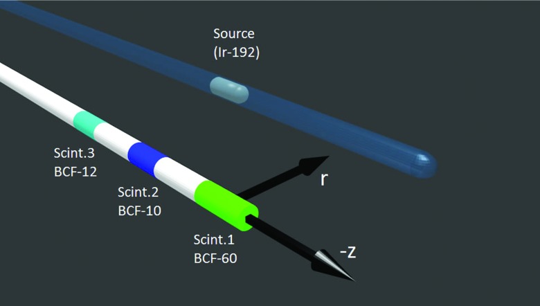
We built a three-point PSD similar to one described in a previous report.28 The same scintillating elements were used (BCF-10, BCF-12, and BCF-60; Saint-Gobain Crystals, Hiram, OH) but, as shown in Fig. 1, the positions of the BCF-10 and BCF-12 scintillating elements were swapped to optimize the optical separation of the different signals. Since the element at the tip (scintillator #1) is more subject to the attenuation from the multiple interfaces, it was made longer (3 mm) than the two others (2 mm). Scintillating fibers and clear optical fibers (Eska GH-4001; Mitsubishi Rayon Co., Ltd., Tokyo, Japan) were all 1 mm in diameter. The optical stubs (Eska GH-4001) separating scintillating element #1 from #2 and scintillating element #2 from #3 were, respectively, 2.2 and 2.3 cm in length. The proximal end of scintillating element #3 was coupled to a long (∼15 m) polymethyl-metaacrylate clear optical fiber (Eska GH-4001). The coupling between the different light transmission components was improved from that employed in the previous study by using an index-matching epoxy (Epo-Tek 305, AngstromBond; Fiber Optics Center, New Bedford, MA).
Figure 1.
System of coordinates used in this study to express the position of the 192Ir brachytherapy source relative to the mPSD. The center of scintillator (Scint.) #1 was defined as z = 0, r = 0.
The detector was made light-tight by tightly fitting a black jacket pulled from shrink tubing inside the 1.4-mm-diameter catheter. The part of the mPSD that was not inserted inside the catheter was made light-tight by covering it with a polyethylene jacket with an outside diameter of 2.2 mm, and the tip was covered with a 3-mm-long and 1-mm-diameter graphite and polyethylene cap. To enable implementation of the hyperspectral approach described by Archambault et al.,27 we used a spectrograph (Shamrock; Andor Technology, Belfast, Northern Ireland) coupled to a charge-coupled device camera (iDus; Andor Technologies) to measure the optical spectrum of the incoming light from the mPSD. The long optical fiber was connected to the spectrograph through a SubMiniature version A connector (Thorlabs, Newton, NJ).
Delivering the dose
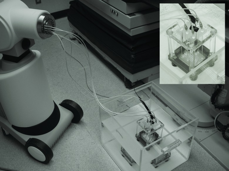
Except for some irradiations used for calibration, all of the irradiations in this study were performed with a HDR brachytherapy 192Ir source (microSelectron v2; Nucletron, Veenendaal, The Netherlands) inside a water tank in which an inhouse-developed catheter-positioning template, described previously and shown in Fig. 2, was placed.20, 29 Catheters for dose delivery were pulled straight inside the template by using clamping buttons (Nucletron) and placed in parallel to a catheter for mPSD insertion at radial distances of r = 1.0, r = 2.0, r = 3.0, and r = 5.0 cm. The source used in this study had an air-kerma strength of 23 976.5 U.
Figure 2.
Experimental setup and positioning template system (embedded). Catheters were connected to transfer tubes, which were connected to the afterloader. The PSD was connected to the spectrometry setup outside the treatment room (Ref. 29).
Calculating the expected dose
A script has been developed using MATLAB (Mathworks, Natick, MA) to calculate the expected dose (Dref) at any given position around the microSelectron v2 192Ir radioactive source. The line source model recommended by Task Group 43 of the American Association of Physicists in Medicine (AAPM) was implemented.30 The expected dose rate () per unit air-kerma strength (SK) was calculated from Eq. 1
| (1) |
The radial dose function g(r), the anisotropy factor F(r, θ), the geometry function G(r, θ), and the dose rate constant Λ in water were determined by Daskalov et al.31 for this particular irradiation source and are used here. Therefore, the expected dose rate could be calculated at any position and the expected dose could be obtained by multiplying the dose rate by the integration time at that position.
Measuring the dose
The recently developed framework for mPSDs is based on the assumption that the detected light is a linear superposition of the light coming from each light-emitting component.27, 28 Therefore, any measured light spectrum (m) can be expressed as a linear superposition of the normalized spectral distribution (r) of all of its light components [see Eqs. 2, 3]
| (2) |
| (3) |
where x represents the vector containing the intensity factors from each light-emitting component which include the three scintillating elements and the stem effect. The solution for x in this system of equations can be obtained by using the left pseudoinverse technique27 and is given by
| (4) |
To obtain the dose to each scintillating element from the vector x obtained under any irradiation condition, at least one known-dose (Di,calib) irradiation to each scintillating element must be performed and the associated intensity factor (xi,calib) under this condition determined. The dose under any condition can then be calculated from the following:
| (5) |
The stem effect light spectrum, even if composed of fluorescence and Cerenkov light, does not vary much among different irradiation conditions for the HDR brachytherapy 192Ir source used in this study.32 Therefore, only a single stem effect spectrum is required to account for the combined fluorescence and Cerenkov light. This spectrum (rStem) was acquired through irradiation of the clear optical fiber prior to the mPSD assembly using the HDR brachytherapy 192Ir source. Once the mPSD was assembled, the scintillating elements’ light spectra were obtained by irradiating each of the scintillating elements individually using a lead-collimated (2-mm diameter) 125 kVp x-ray beam from a superficial therapy unit (Philips RT-250; Philips Medical Systems, Andover, MA). Irradiating only the scintillating elements with a beam of energy under the threshold for Cerenkov production in PMMA (∼178 keV) allowed recording spectra that were assumed to be purely coming from the scintillation. All spectra were normalized to the area under the curve.
In the next step, the 192Ir source was moved along the z-axis (Fig. 1) by 0.5-cm steps over a total range of 10.5 cm in the source delivery catheter at r = 2 cm, and at least three 5-s acquisitions were performed per source position. The values obtained for xmeas were fitted with the expected dose distributions along z for the different radial distances. This allowed determination of the position of effective maximum light emission from each of the scintillating elements. The position of that maximum for scintillating element #1 was defined as the z = 0 cm reference (Fig. 1). The scintillating element #2 emission peak was determined to be z = 2.53 cm and that of scintillating element #3 z = 4.99 cm, both of which correspond quite well to the expected distances between the scintillating elements calculated for actual construction of the mPSD. To complete the process of calibration of the mPSD, the measurements performed for the 192Ir source positions of r = 2 cm and z = −0.11, z = 2.39, and z = 4.89 cm were used to determine the calibration factors (Dcalib and xcalib) for scintillating elements #1, #2, and #3, respectively. With the calibration factors determined, dose could then be calculated from any other measurements using Eq. 5.
Assessing the uncertainties
The error propagation in this experiment was carried out, as proposed by Andersen et al.,6 using a simple Monte Carlo technique where any variable was assumed to follow a Gaussian distribution of average μ and standard deviation σ. For example, the uncertainty on the source-to-detector position was used to determine the uncertainty on the calibration doses as well as any other expected dose. The uncertainty in source-to-detector positioning using the template was assumed to be the same (Δr = ±0.2 mm, Δz = ±0.4 mm) as in previous studies that used the same template.20, 29 Independent values were sampled for r and z from a normal distribution with a mean given by the expected position and the standard deviation being equal to the uncertainty in positioning. The dose corresponding to this position was then calculated. This process was repeated 10 000 times, resulting in a distribution of error-convoluted dose values. The mean and standard deviation of this distribution were considered to be the average dose and its associated uncertainty. This was performed for all of the dwell positions used in this study. This error propagation process was used for the calculation of various parameters during this experiment as defined in Table 1.
Table 1.
The variables of dose determination and how uncertainties were calculated.
| Variable | Description | Uncertainty |
|---|---|---|
| m | Measured spectrum | Standard deviation over multiple measurements for each wavelength (2 nm bins) of the total spectrum. |
| R | Normalized light-emitting spectra | Standard deviation over multiple measurements for each wavelength (2 nm bins) of the four individual spectra. |
| xmeas, xcalib | Intensity factor under measurement (meas) or calibration (calib) conditions | Standard deviation of the distribution obtained by Eq. 4 from sampling of m and R. |
| Dcalib | Calibration dose | Standard deviation of the calibration dose distribution obtained from repeated sampling of the source-to-detector calibration position with Eq. 1. |
| Dmeas | Measured dose | Standard deviation of the dose distribution obtained by Eq. 5 from repeated sampling of Dcalib, xmeas, and xcalib. |
| Dref | Reference or expected dose | Standard deviation of the expected dose distribution obtained from repeated sampling of the source-to-detector measurement positions with Eq. 1. |
The uncertainties on Dcalib and Dref were subject only to the positioning uncertainties, while the calculation of Dmeas relied on multiple variables as expressed in Eq. 5. At least three spectra m were acquired for each of the irradiation conditions and dwell positions. After passing each of these spectra through a sliding median filtration process and binning pixels in groups of five (∼2 nm/bin), the average and standard deviation over those multiple spectra were calculated for each of the wavelength values composing the spectra. This allowed determination of the average and uncertainty on m in Eq. 4. The uncertainty on the different spectra composing R was also calculated from multiple spectral acquisitions by following the same process. Assuming normal distributions for R and m, the average and uncertainty on x can be obtained from Eq. 4 using the same independent sampling process explained in the previous paragraph. Finally, knowing the average value and uncertainty of xcalib, xmeas, and Dcalib, the average and uncertainty of the measured dose (Dmeas) can be obtained through the same independent sampling process by using Eq. 5.
Experiments
Basic measurement technique
The 192Ir HDR brachytherapy source was moved from position z = −2.61 to z = 7.89 cm by 0.5-cm steps in each of the catheters. These limits were chosen such that the dwell positions cover at least 2.5 cm below and over the proximal and distal scintillating elements along z. The catheters were placed at radial distances of 1.0, 2.0, 3.0, and 5.0 cm from the mPSD by using the template. The dwell time at each position was over 20 s, such that at least three complete 5-s acquisitions could be performed per dwell position. The measured dose to each position was obtained and compared to the expected dose by calculating the accuracy (or relative difference) as defined in Eq. 6
| (6) |
Multiple scintillator weighted approach
Having access to dose measurements from multiple scintillating elements along the same line should improve the decision process during in vivo dosimetry for HDR brachytherapy, i.e., whether treatment delivery should be halted because of a detected inconsistency with the dose expected from the treatment plan. Therefore, a weighted approach was investigated to improve detector accuracy by using combined information from all three scintillating elements and defined as follows:
| (7) |
where Wi is the weight and Mi is the output parameter from each scintillating element i. In this particular case, M corresponds to the accuracy. The weighting factor used in this study was the squared dose divided by the squared standard deviation (D2/σ2).33
Using a dose threshold
Another approach investigated to improve the error decision process was imposition of a dose threshold on the measurements such that a measurement at a point where the dose is under the threshold will not be taken into account. Various threshold values were studied (1, 3, 5, and 10 cGy).
Integration time analysis
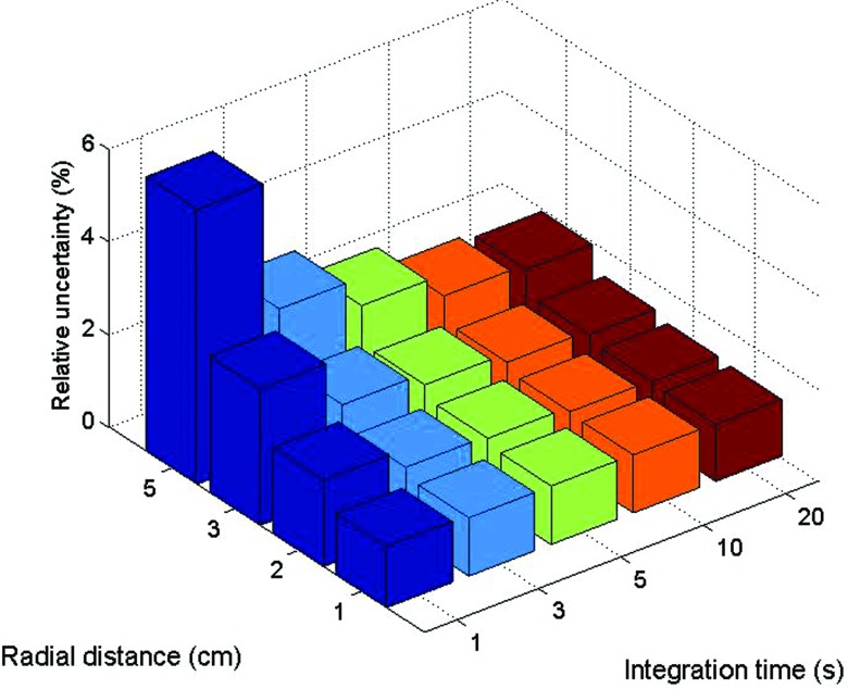
The impacts of integration time and of radial distance on the uncertainty of the measured dose were also investigated. For a single dwell position per catheter (z = 2.39 cm) and a dwell time of 90 s, acquisitions were performed with different integration times (1, 3, 5, 10, and 20 s). The relative uncertainty was calculated from the ratio between the standard deviation and average over the multiple acquisitions performed at each position.
Uncertainty sources
The uncertainty was calculated on each of the dose measurements and accuracy calculations in this study. Nevertheless, it was also important to evaluate the source of these uncertainties. To break down the impacts of positioning and measurement uncertainties on accuracy calculation [see Eq. 5], the sampling process was performed three times: once with measurement as the only variable (normal distribution with standard deviation), once with position as the only variable, and once with both measurement and position uncertainties accounted for.
Source position accuracy
Finally, the ability of the three-point mPSD to detect the radioactive source position was tested. Knowing the expected dose distribution along z for a particular radial distance, the position on z was inferred from the measured dose from each of the scintillating elements at the four different radial distances. Since the mPSD is held straight inside a catheter and the distance between the scintillators is known, the measured positions were combined, which should lead to better accuracy in position determination than use of any one scintillating element independently. The weighted approach was also investigated for this experiment. Furthermore, to physically evaluate the source positioning uncertainty from the afterloader, irradiations at seven different dwell positions 1 cm apart were repeated five times with the mPSD fixed to the same position. The calculated uncertainty was compared to the estimated value of 0.4 mm.
RESULTS
The doses and associated uncertainties measured with each of the scintillating elements composing the mPSD are shown in Fig. 3 for various r and z positions. The expected doses are also represented. The accuracy of each scintillating element in measuring dose was calculated by using Eq. 6 and is shown in the bottom panels of Fig. 3. The average over the accuracy measurements was calculated for each radial distance and is shown in Table 2 for each scintillating element.
Figure 3.
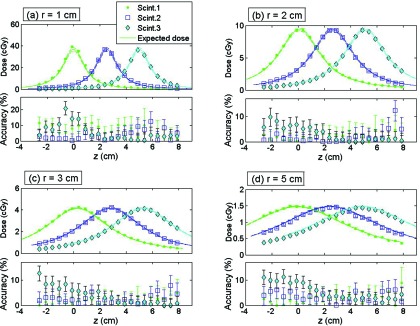
For (a) r = 1 cm, (b) r = 2 cm, (c) r = 3 cm, and (d) r = 5 cm: (Top) Dose measured by each scintillating element (Scint.) together with the calculated expected dose. (Bottom) Accuracy of the measurement. Scint.1 is at z = 0 cm, scint. 2 at z = 2.53 cm, and scint. 3 at z = 4.99 cm.
Table 2.
Averaged accuracy and standard deviation (sd) for dose measurement by each scintillating element (Scint.) of the mPSD and with the weighted combination for different radial distances r.
| Averaged accuracy ± sd (%) |
||||
|---|---|---|---|---|
| Scint. 1 | Scint. 2 | Scint. 3 | Weighted | |
| r = 1 cm | 7.0 ± 3.3 | 3.7 ± 3.2 | 5.4 ± 5.2 | 4.6 ± 3.2 |
| r = 2 cm | 2.1 ± 1.4 | 2.0 ± 2.6 | 3.2 ± 2.9 | 0.8 ± 0.6 |
| r = 3 cm | 1.7 ± 1.2 | 2.7 ± 1.8 | 3.8 ± 3.4 | 0.7 ± 0.4 |
| r = 5 cm | 2.8 ± 2.0 | 3.5 ± 1.8 | 5.6 ± 3.2 | 1.9 ± 1.0 |
Accuracy, precision, and the multiple scintillator technique
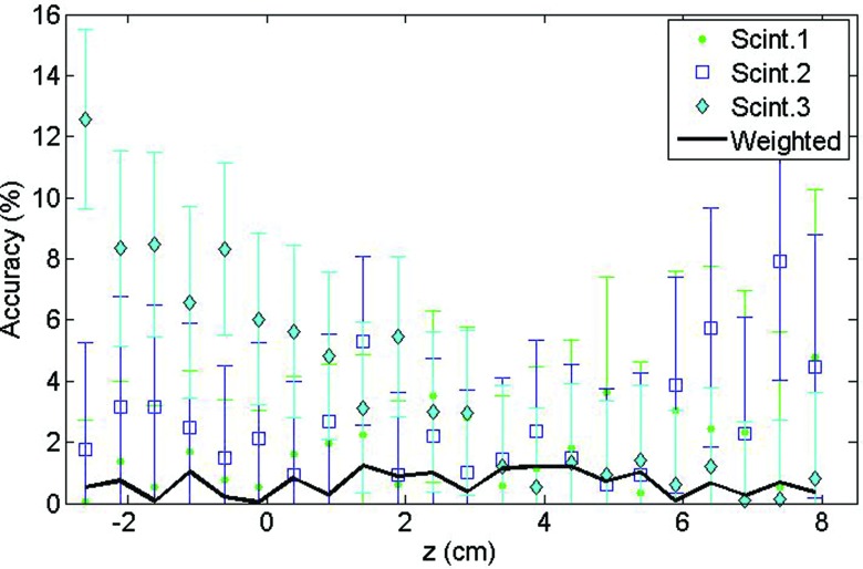
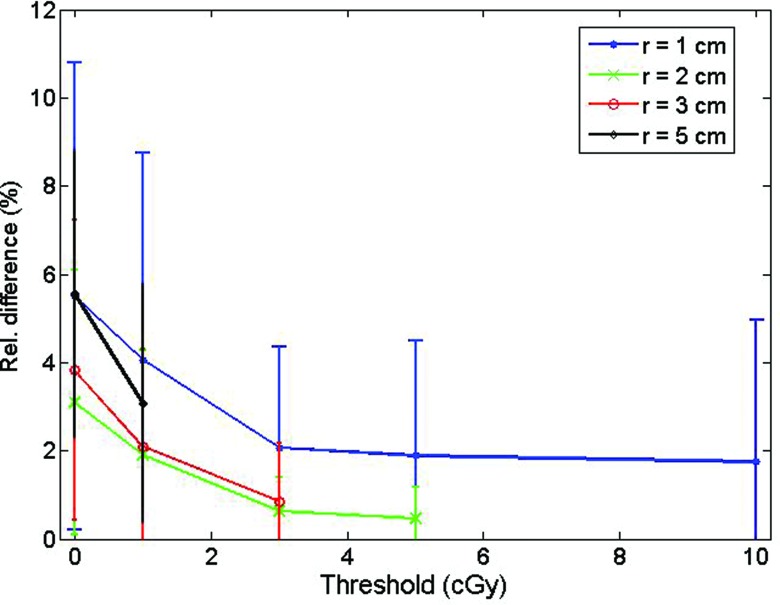
The accuracy and precision of the detector were improved by taking advantage of the multiple simultaneous measurements in a combined, weighted function. Figure 4 shows the improvement obtained by using this approach in comparison to each scintillating element individually for multiple source positions at r = 3 cm. The rightmost column of Table 2 gives the averaged accuracies obtained for the different radial distances. Accuracy also was improved by considering only the positions where the dose was over a certain threshold, as depicted in Fig. 5. As would be expected, the accuracy improved progressively with increasing threshold values.
Figure 4.
Effect of the weighted approach combining measurements from each scintillating element (Scint.) on dose measurement accuracy at r = 3 cm.
Figure 5.
Effect of various dose thresholds on the averaged accuracy measurement for scintillating element #3.
Effect of integration time and radial distance
The choice of integration time impacted the relative uncertainty of the measured values. Figure 6 demonstrates that the relative uncertainty of measurements coming from scintillating element #2 decreased with longer integration. This decrease came at the expense of a loss in temporal resolution. Furthermore, the relative uncertainty increased with increasing radial distance.
Figure 6.
Relative uncertainty of the measurements from scintillating element #2 as a function of integration time and radial source-to-mPSD distance.
According to Fig. 7, the precision depended strongly on the uncertainty associated with positioning, but also on uncertainty in the dose measurement. The uncertainty on measurement was particularly important for lower dose rates.
Figure 7.
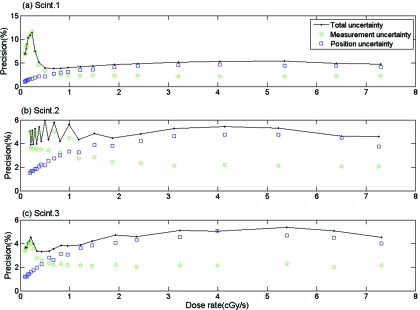
Effects of the measurement, position, and total uncertainties on precision for all three scintillating elements: (a) Scint. 1, (b) Scint. 2, (c) Scint. 3 at r = 1 cm.
Source position detection
Determining the source position appears to be a promising application for the mPSD, taking advantage of its multipoint capacity. Figure 8 shows a map of the offsets between the expected and measured positions of the 192Ir source for each scintillating element and for the weighted approach as a function of positions r and z. The offsets were higher with increasing distance from the scintillating elements. Proportions of measurements above or below certain threshold offset values were calculated and are presented in Table 3 for offset values of 0.5, 1.0, and 2.0 mm. The weighted approach improved source position detection, as lower positioning offsets were obtained (see Table 3). Finally, using the weighted approach, the source positioning uncertainty from the afterloader in the z direction was measured to be no more than 0.32 ± 0.06 mm. This agreed well with the assumed source position uncertainty along the z direction used in this study, 0.4 mm.
Figure 8.
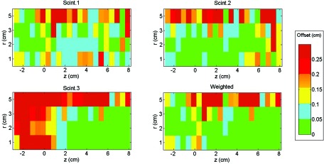
Maps of the offset between the expected and calculated positions of the 192Ir source as a function of the position of each of the scintillators (Scint.) and of the weighted approach. Scintillator 1 is at z = 0 cm, scintillator 2 at z = 2.53 cm, and scintillator 3 at z = 4.99 cm.
Table 3.
Proportion of the measured positions above or below a certain position offset threshold for the each scintillating element (Scint.) and for the weighted approach.
| Offset < 0.5 mm (%) | Offset < 1 mm (%) | Offset > 2 mm (%) | |
|---|---|---|---|
| Scint. 1 | 28 | 60 | 11 |
| Scint. 2 | 43 | 63 | 16 |
| Scint. 3 | 36 | 47 | 38 |
| Weighted | 59 | 69 | 13 |
DISCUSSION
Improvements over previous mPSD
The dose measurements performed with the three-point plastic scintillation detector were in good agreement with the expected dose calculated from the Task Group 43 formalism and Daskalov et al.31-recommended parameters for the microSelectron v2 192Ir source.30 The three scintillating elements showed comparable accuracies, with average values of 3.4 ± 2.1% for scintillator #1, 3.0 ± 0.7% for scintillator #2, and 4.5 ± 1.0% for scintillator #3. The similarity between the accuracies was an improvement on the mPSD previously used.28 The difference can be explained by modifications made in construction of the detector.
The change in the position of the scintillating elements (swap between BCF-10 and BCF-12) was made such that the scintillating element whose emission spectrum overlapped the most with other light-emitting spectra was placed closest to the photodetection setup. This contrasted with the fact that this position was less subject to optical attenuation from multiple interfaces. The use of an index-matching epoxy also helped to decrease the attenuation at each coupling interface and, indeed, increased the intensity of the signal from scintillating elements #1 and #2 that made it up to the spectrometry setup. Increasing the length of the distal scintillating element (#1) contributed to its accuracy improvement relative to the other elements.
Accuracy and position
Table 2 reveals that the worst accuracies were obtained for the source positions radially the closest to the mPSD. Even if the generated light signals were higher because of the stronger doses at these positions, the higher dose gradients led to a substantial uncertainty on the expected dose due to the uncertainty in source positioning, a small position error leading to high discrepancies. This can be seen on Fig. 3a for r = 1 cm where the expected dose range was larger than for other radial distances [Figs. 3b, 3c, 3d]. At this distance, gradients up to 15% mm−1 were observed. Notably, the expected dose values in this study were calculated from a finite point in space with the dose distribution line-source model.30, 31 For small radial distances, approximating the scintillator as a point in space may not be completely accurate. The dose gradient not being constant in that region, a spatial integration over the scintillator's volume would have led to higher expected doses.
However, this effect falls off as the radial distance from the source increases. As an example, for z = 0, averaging the dose at r = 0.95 cm and the dose at r = 1.05 cm leads to a dose that is 0.75% higher than the point dose at r = 1.0 cm. The same calculation around r = 2, r = 3, and r = 5 cm leads to respective discrepancies in the expected dose of 0.2%, 0.07%, and 0.02%. If this shows a stronger effect along the radial direction, the same discussion can be held about the dose distribution along the z-axis. It is also important to consider here that the uncertainty on the expected dose was solely accounted for by the uncertainty in positioning. AAPM Task Group 138 and GEC-ESTRO reported the expanded relative propagated uncertainty (k = 2 or 95% confidence level) for dose at 1 cm of high-energy brachytherapy sources along their transverse plane to be 6.8%.34 The reported average accuracies and associated uncertainty for r = 1 cm of the present study, shown in Table 2, are not statistically different than that value. It is also interesting to note that the averaged accuracies reported for each scintillating element at the beginning of this section are all close to the best practice uncertainty on measured dose of 3.0% reported by the AAPM and GEC-ESTRO groups for high-energy brachytherapy sources.34
Dose threshold effect
Most of the 22 different dwell positions used for the measurement of doses represented in Figs. 3a, 3b, 3c, 3d were in a quite low dose region (<1 cGy/s). It can be seen on Fig. 5 that considering only the positions where the delivered dose was over a certain dose threshold led to improvement of the average measurement accuracy. For this study, a threshold of 3 cGy appeared to strike a good balance between improving the accuracy of the mPSD and discarding too many measurement conditions. Another way to improve the accuracy of the mPSD was to take advantage of the simultaneous measurements at multiple positions. The use of the weighted approach is recommended for future use.
Clinical considerations and integration time
It was no surprise to observe improvement in the relative uncertainty of the measurements as the integration time was prolonged and as the source got closer to the mPSD, as represented in Fig. 6. Since longer time of integration and shorter radial distance mean higher doses, the amount of light collected was then increased considerably. However, it is advantageous in an in vivo dosimetry system to keep the integration time as short as possible in order to increase the temporal resolution and to be able to measure the dose delivered during shorter dwell times. With the present mPSD, an integration time of 3 s or longer would be recommended, since that would keep the relative uncertainty of the scintillator represented here under 2.5% for all radial distances. This would represent a good balance between temporal resolution and uncertainty on dose for this particular situation and would allow verification of the dose rate in real time for most of the dwell positions of a HDR brachytherapy treatment, including monitoring the source retraction from a given catheter.20
Positional uncertainty effects on dose rate and accuracy
Our examination of the source of uncertainties revealed that positioning uncertainty and measurement uncertainties are important, with different contributions depending on the dose rate. The uncertainty on the intensity factor xmeas increases as the source moves away from the scintillating element along the z-axis, and this supports the higher contribution from the measurement uncertainties on the precision under lower dose-rate conditions. This was not surprising since the uncertainty on xmeas depends on the uncertainty of the spectral acquisition m, which is more subject to noise as the dose gets smaller. It may be noted from Fig. 7 that the precision was not constant for scintillator #2 at the lowest dose rates. This actually depended on which side of the mPSD the 192Ir source was positioned.
The worst precision was recorded with the source far from the scintillating element on the collecting fiber side. At this position, the competition between signals with overlapping spectra [BCF-10 (cyan), BCF-12 (blue), and stem-effect (wide-spectrum)] may explain a decreasing ability to decouple precisely the different signals in comparison to the case where the competing signals are mostly coming from only two sources [BCF-60 (green) and BCF-10 (blue)]. The precision from the measurement was constant and a non-negligible factor at higher dose rates (around 2%), which can be explained by the fact that even if the uncertainty on xmeas decreased, the effect from the uncertainty on the calibration (Dcalib and xcalib) was constant.
Clinical application
Finally, mPSD was shown to be very promising for detection of 192Ir source position. Since the catheters used for dose delivery were parallel to the catheter used for mPSD insertion, it was possible to infer the source position from dose measured by each of the individual scintillating elements. However, as can be observed in Fig. 8 and Table 3, the accuracy of position determination was improved by the weighted approach using information coming from the three scintillating elements simultaneously. Indeed, the source positions were almost always close to at least one of the scintillating elements, and the weighted approach led to signal-to-noise ratio always acceptable for source-to-detector position calculation. This was true for most of the radial positions, but the signal-to-noise ratio at r = 5 cm appeared to be too low to achieve measurement accuracy comparable to those of the other positions. The positioning measurement also verified that the estimated uncertainty in z-positioning of 0.4 mm was realistic, since the average measured offset between the measurement and expected positions was 0.32 ± 0.06 mm.
In this experiment, the mPSD was used for source positioning measurements with all catheters being parallel. This technique could also be used in a setup in which all the source coordinates are unknown (i.e., by triangulation). To do this, however, the position of each scintillator relative to all others has to be known. These positions would be quite easy to determine for mPSDs, since the physical distance is defined during the construction process and can be verified during the calibration of the detector as it was done in this study.
The development of a multipoint detector using only a single optical collection fiber is very promising for clinical applications as it enables in vivo measurement of the dose at multiple points during HDR brachytherapy without having to implant or insert multiple detectors. Indeed, the mPSD technique proposed here is less invasive and more versatile than multipoint detection methods developed previously. The detector developed by Cartwright et al.16 for dose measurements at the rectal wall contained 16 scintillators and was a promising application of multiple single PSDs for HDR brachytherapy, but its diameter was 20 mm, which is almost ten times larger than the single-fiber three-point mPSD used in this work. In contrast with the mPSD presented here, the detector presented by Cartwright et al.16 lacked a Cerenkov and stem effect suppression technique, which could be problematic under some irradiation conditions, as already pointed out.29 Finally, the mPSD offers better source position detection (Table 3) than the 2 mm reported by Cartwright et al.16 The mPSD represents an important step toward acceptance of in vivo dose detector implementation in the clinic.
CONCLUSION
In this study, the feasibility of using a mPSD to perform accurate dosimetry during 192Ir HDR brachytherapy was demonstrated in a water phantom. The ability to assess dose at multiple positions simultaneously through insertion of a single millimetric water-equivalent detector is a very promising innovation for HDR brachytherapy. Basic optimization during the construction of the three-point mPSD improved the overall accuracy of the detector. Considering only the measurements when the dose to a given scintillator was over a 3-cGy threshold and merging the output from the three scintillating elements through a weighting function increased its dose measuring accuracy and precision. The choice of integration time was shown to involve a trade-off between temporal resolution and measurement uncertainty. Knowing the relative positions of the multiple scintillating elements along a single optical transmission line was shown to improve the accuracy of detection of the radioactive source position. The use of single-fiber mPSDs in the clinic should lead the way to safer treatment delivery with minimum invasiveness for patients.
ACKNOWLEDGMENTS
This work was supported in part by a Discovery grant from the Natural Sciences and Engineering Research Council of Canada (Grant No. 262105) and by a grant from the U.S. National Cancer Institute (Grant No. 1R01CA120198-01A2).
References
- Jursinic P. A. and Yahnke C. J., “In vivo dosimetry with optically stimulated luminescent dosimeters, OSLDs, compared to diodes; the effects of buildup cap thickness and fabrication material,” Med. Phys. 38, 5432–5440 (2011). 10.1118/1.3633939 [DOI] [PubMed] [Google Scholar]
- Ludemann L., Wybranski C., Seidensticker M., Mohnike K., Kropf S., Wust P., and Ricke J., “In vivo assessment of catheter positioning accuracy and prolonged irradiation time on liver tolerance dose after single-fraction 192Ir high-dose-rate brachytherapy,” Radiat. Oncol. 6, 1–10 (2011). 10.1186/1748-717X-6-107 [DOI] [PMC free article] [PubMed] [Google Scholar]
- Seymour E. L., Downes S. J., Fogarty G. B., Izard M. A., and Metcalfe P., “In vivo real-time dosimetric verification in high dose rate prostate brachytherapy,” Med. Phys. 38, 4785–4794 (2011). 10.1118/1.3615161 [DOI] [PubMed] [Google Scholar]
- Anagnostopoulos G., Baltas D., Geretschlaeger A., Martin T., Papagiannis P., Tselis N., and Zamboglou N., “In vivo thermoluminescence dosimetry dose verification of transperineal 192Ir high-dose-rate brachytherapy using CT-based planning for the treatment of prostate cancer,” Int. J. Radiat. Oncol., Biol., Phys. 57, 1183–1191 (2003). 10.1016/S0360-3016(03)00762-4 [DOI] [PubMed] [Google Scholar]
- Andersen C. E., Nielsen S. K., Greilich S., Helt-Hansen J., Lindegaard J. C., and Tanderup K., “Characterization of a fiber-coupled Al2O3:C luminescence dosimetry system for online in vivo dose verification during 192Ir brachytherapy,” Med. Phys. 36, 708–718 (2009). 10.1118/1.3063006 [DOI] [PubMed] [Google Scholar]
- Andersen C. E., Nielsen S. K., Lindegaard J. C., and Tanderup K., “Time-resolved in vivo luminescence dosimetry for online error detection in pulsed dose-rate brachytherapy,” Med. Phys. 36, 5033–5043 (2009). 10.1118/1.3238102 [DOI] [PubMed] [Google Scholar]
- Bloemen-van Gurp E. J., Haanstra B. K., Murrer L. H., van Gils F. C., Dekker A. L., Mijnheer B. J., and Lambin P., “In vivo dosimetry with a linear MOSFET array to evaluate the urethra dose during permanent implant brachytherapy using iodine-125,” Int. J. Radiat. Oncol., Biol., Phys. 75, 1266–1272 (2009). 10.1016/j.ijrobp.2009.04.042 [DOI] [PubMed] [Google Scholar]
- Brezovich I. A., Duan J., Pareek P. N., Fiveash J., and Ezekiel M., “In vivo urethral dose measurements: A method to verify high dose rate prostate treatments,” Med. Phys. 27, 2297–2301 (2000). 10.1118/1.1312811 [DOI] [PubMed] [Google Scholar]
- Cherpak A., Ding W., Hallil A., and Cygler J. E., “Evaluation of a novel 4D in vivo dosimetry system,” Med. Phys. 36, 1672–1679 (2009). 10.1118/1.3100264 [DOI] [PubMed] [Google Scholar]
- Gambarini G., Borroni M., Grisotto S., Maucione A., Cerrotta A., Fallai C., and Carrara M., “Solid state TL detectors for in vivo dosimetry in brachytherapy,” Appl. Radiat. Isot. 71(Suppl. 48–51) (2012). (Epub 2012). 10.1016/j.apradiso.2012.06.018 [DOI] [PubMed] [Google Scholar]
- Haughey A., Coalter G., and Mugabe K., “Evaluation of linear array MOSFET detectors for in vivo dosimetry to measure rectal dose in HDR brachytherapy,” Australas. Phys. Eng. Sci. Med. 34, 361–366 (2011). 10.1007/s13246-011-0084-2 [DOI] [PubMed] [Google Scholar]
- Mijnheer B., “State of the art of in vivo dosimetry,” Radiat. Prot. Dosim. 131, 117–122 (2008). 10.1093/rpd/ncn231 [DOI] [PubMed] [Google Scholar]
- Mrcela I., Bokulic T., Izewska J., Budanec M., Frobe A., and Kusic Z., “Optically stimulated luminescence in vivo dosimetry for radiotherapy: Physical characterization and clinical measurements in (60)Co beams,” Phys. Med. Biol. 56, 6065–6082 (2011). 10.1088/0031-9155/56/18/018 [DOI] [PubMed] [Google Scholar]
- Reniers B., Landry G., Eichner R., Hallil A., and Verhaegen F., “In vivo dosimetry for gynaecological brachytherapy using a novel position sensitive radiation detector: Feasibility study,” Med. Phys. 39, 1925–1935 (2012). 10.1118/1.3693049 [DOI] [PubMed] [Google Scholar]
- Toye W., Das R., Kron T., Franich R., Johnston P., and Duchesne G., “An in vivo investigative protocol for HDR prostate brachytherapy using urethral and rectal thermoluminescence dosimetry,” Radiother. Oncol. 91, 243–248 (2009). 10.1016/j.radonc.2008.08.016 [DOI] [PubMed] [Google Scholar]
- Cartwright L. E., Suchowerska N., Yin Y., Lambert J., Haque M., and McKenzie D. R., “Dose mapping of the rectal wall during brachytherapy with an array of scintillation dosimeters,” Med. Phys. 37, 2247–2255 (2010). 10.1118/1.3397446 [DOI] [PubMed] [Google Scholar]
- Kertzscher G., Andersen C. E., Siebert F. A., Nielsen S. K., Lindegaard J. C., and Tanderup K., “Identifying afterloading PDR and HDR brachytherapy errors using real-time fiber-coupled Al(2)O(3):C dosimetry and a novel statistical error decision criterion,” Radiother. Oncol. 100, 456–462 (2011). 10.1016/j.radonc.2011.09.009 [DOI] [PubMed] [Google Scholar]
- Lambert J., McKenzie D. R., Law S., Elsey J., and Suchowerska N., “A plastic scintillation dosimeter for high dose rate brachytherapy,” Phys. Med. Biol. 51, 5505–5516 (2006). 10.1088/0031-9155/51/21/008 [DOI] [PubMed] [Google Scholar]
- Lambert J., Nakano T., Law S., Elsey J., McKenzie D. R., and Suchowerska N., “In vivo dosimeters for HDR brachytherapy: A comparison of a diamond detector, MOSFET, TLD, and scintillation detector,” Med. Phys. 34, 1759–1765 (2007). 10.1118/1.2727248 [DOI] [PubMed] [Google Scholar]
- Therriault-Proulx F., Briere T. M., Mourtada F., Aubin S., Beddar S., and Beaulieu L., “A phantom study of an in vivo dosimetry system using plastic scintillation detectors for real-time verification of 192Ir HDR brachytherapy,” Med. Phys. 38, 2542–2551 (2011). 10.1118/1.3572229 [DOI] [PMC free article] [PubMed] [Google Scholar]
- Tien C. J., R.EbelingIII, Hiatt J. R., Curran B., and Sternick E., “Optically stimulated luminescent dosimetry for high dose rate brachytherapy,” Front. Oncol. 2, 1–7 (2012). 10.3389/fonc.2012.00091 [DOI] [PMC free article] [PubMed] [Google Scholar]
- Waldhausl C., Wambersie A., Potter R., and Georg D., “In-vivo dosimetry for gynaecological brachytherapy: Physical and clinical considerations,” Radiother. Oncol. 77, 310–317 (2005). 10.1016/j.radonc.2005.09.004 [DOI] [PubMed] [Google Scholar]
- Zilio V. O., Joneja O. P., Popowski Y., Rosenfeld A., and Chawla R., “Absolute depth-dose-rate measurements for an 192Ir HDR brachytherapy source in water using MOSFET detectors,” Med. Phys. 33, 1532–1539 (2006). 10.1118/1.2198168 [DOI] [PubMed] [Google Scholar]
- Beddar A. S., “Plastic scintillation dosimetry and its application to radiotherapy,” Radiat. Meas. 41, S124–S133 (2006). 10.1016/j.radmeas.2007.01.002 [DOI] [Google Scholar]
- Beddar A. S., Mackie R., and Attix F. H., “Water-equivalent plastic scintillation detector for high energy beam dosimetry: I. Physical characteristics and theoretical considerations,” Phys. Med. Biol. 37, 1883–1900 (1992). 10.1088/0031-9155/37/10/006 [DOI] [PubMed] [Google Scholar]
- Beddar A. S., Mackie T., and Attix F. H., “Water-equivalent plastic scintillation detector for high-energy beam dosimetry: II. Properties and measurements,” Phys. Med. Biol. 37, 1901–1913 (1992). 10.1088/0031-9155/37/10/007 [DOI] [PubMed] [Google Scholar]
- Archambault L., Therriault-Proulx F., Beddar S., and Beaulieu L., “A mathematical formalism for hyperspectral, multi-point, plastic scintillation detectors,” Phys. Med. Biol. 57, 7133–7145 (2012). 10.1088/0031-9155/57/21/7133 [DOI] [PubMed] [Google Scholar]
- Therriault-Proulx F., Archambault L., Beaulieu L., and Beddar S., “Development of a novel multi-point plastic scintillation detector with a single optical transmission line for radiation dose measurement,” Phys. Med. Biol. 57, 7147–7160 (2012). 10.1088/0031-9155/57/21/7147 [DOI] [PMC free article] [PubMed] [Google Scholar]
- Therriault-Proulx F., Beddar S., Briere T. M., Archambault L., and Beaulieu L., “Technical note: Removing the stem effect when performing Ir-192 HDR brachytherapy in vivo dosimetry using plastic scintillation detectors: A relevant and necessary step,” Med. Phys. 38, 2176–2179 (2011). 10.1118/1.3562902 [DOI] [PMC free article] [PubMed] [Google Scholar]
- Nath R., Anderson L. L., Luxton G., Weaver K. A., Williamson J. F., and Meigooni A. S., “Dosimetry of interstitial brachytherapy sources: Recommendations of the AAPM Radiation Therapy Committee Task Group No. 43. American Association of Physicists in Medicine,” Med. Phys. 22, 209–234 (1995). 10.1118/1.597458 [DOI] [PubMed] [Google Scholar]
- Daskalov G. M., Loffler E., and Williamson J. F., “Monte Carlo-aided dosimetry of a new high dose-rate brachytherapy source,” Med. Phys. 25, 2200–2208 (1998). 10.1118/1.598418 [DOI] [PubMed] [Google Scholar]
- Therriault-Proulx F., Beaulieu L., Archambault L., and Beddar S., “On the nature of the light produced within PMMA optical light guides in scintillation fiber-optic dosimetry,” Phys. Med. Biol. 58, 2073–2084 (2013). 10.1088/0031-9155/58/7/2073 [DOI] [PMC free article] [PubMed] [Google Scholar]
- Leo W. R., Techniques for Nuclear and Particle Physics Experiments: A How to Approach (Springer-Verlag, Berlin Heidelberg, Germany, 1987). [Google Scholar]
- DeWerd L. A., Ibbott G. S., Meigooni A. S., Mitch M. G., Rivard M. J., Stump K. E., Thomadsen B. R., and Venselaar J. L., “A dosimetric uncertainty analysis for photon-emitting brachytherapy sources: Report of AAPM Task Group No. 138 and GEC-ESTRO,” Med. Phys. 38, 782–801 (2011). 10.1118/1.3533720 [DOI] [PMC free article] [PubMed] [Google Scholar]


