

Abstract
Focusing of light in the diffusive regime inside scattering media has long been considered impossible. Recently, this limitation has been overcome with time reversal of ultrasound-encoded light (TRUE), but the resolution of this approach is fundamentally limited by the large number of optical modes within the ultrasound focus. Here, we introduce a new approach, time reversal of variance-encoded light (TROVE), which demixes these spatial modes by variance-encoding to break the resolution barrier imposed by the ultrasound. By encoding individual spatial modes inside the scattering sample with unique variances, we effectively uncouple the system resolution from the size of the ultrasound focus. This enables us to demonstrate optical focusing and imaging with diffuse light at unprecedented, speckle-scale lateral resolution of ~ 5 μm.
Introduction
Scattering of light by inhomogeneous media poses a fundamental challenge to numerous applications in astronomy, biomedical imaging and colloidal optics. For a long time, scattered light has been viewed as a source of noise. Many advanced imaging approaches have been developed to filter it out, relying solely on the ballistic light component. However, this strategy is futile in strongly scattering media, such as optical diffusers, paint or thick layers of biological tissue, in which the ballistic component approaches zero. Focusing into such samples has therefore long been considered impossible.
Recent developments in the field of wavefront shaping have changed this view 1, demonstrating that scattered light can be utilized for optical focusing beyond the ballistic regime. As light travels across a strongly scattering medium, the wavefront leaving the sample is seemingly randomized. But, in fact, there is a linear mapping between the optical modes in the input wavefront and the optical modes in the output wavefront, which can be fully described by a scattering transmission matrix. These linear, deterministic and time-symmetric properties of scattering 2 have been harnessed for focusing and image transfer across complex samples by iterative wavefront optimization 3–8, time reversal 9, 10 or directly measuring and inverting the transmission matrix 11–15.
Despite these significant advances in our understanding of wavefront control across scattering media, the methods outlined above require direct access to both sides of the medium (i.e. the input plane and the target plane). These approaches are therefore not directly applicable when the goal is to focus between or deep inside scattering media. In such cases, wavefront optimization requires the assistance of beacons or so-called “guide-stars” in the target plane. Guide-stars have successfully been implemented using second-harmonic 16 or fluorescent 17 particles, but optical focusing inside scattering samples is limited to the vicinity of these stationary particles. An alternative approach, termed time reversal of ultrasound-encoded light (TRUE) 18–22, shows much promise for non-invasive imaging by taking advantage of virtual acousto-optic beacons. In this approach, an ultrasound focus frequency-shifts the scattered optical wavefront within a scattering sample thus creating a source of frequency-shifted light. Scattered, frequency-shifted light emanating from this source is recorded outside the tissue and time-reversed by optical phase conjugation to converge back onto the location of the ultrasound focus. Despite its ability to focus inside scattering samples at unprecedented depths, the resolution of TRUE imaging is fundamentally limited by the size of the ultrasound beacon, which is at least an order of magnitude larger (tens of micrometres at best) than the optical speckle size (micrometre-scale).
Here, we propose a way to break this resolution barrier imposed by the size of the beacon by time reversal of variance-encoded light (TROVE). TROVE takes advantage of a spatially unique variance structure imposed by spatially overlapping acoustic foci to encode the spatial location of individual optical speckles within the ultrasound focus. Upon optical time reversal of computationally decoded modes, we achieve focusing at the scale of single optical speckles with diffuse light.
Results
Principles
To better understand the resolution limitation of TRUE imaging and how we can overcome this limitation by variance encoding in TROVE, we can conceptually divide any scattering medium into two sections: one, through which the input light passes before reaching the ultrasound focus and a second, through which the ultrasound-shifted light passes on the way out of the medium. We can make this division without loss of generality for different illumination and recording geometries (see, for example, 19). The process of TRUE focusing thus can be summarized by the following two steps (illustrated in Figure 1a): First, an input wavefront is randomized as it passes through the first half of the sample, resulting in a speckled wavefront b at the ultrasound focus. Part of this wavefront is frequency-shifted via the acousto-optic effect, resulting in a frequency-shifted optical field b′. Because the ultrasound focus is much larger than the optical wavelength, this field contains many optical modes – typically hundreds to thousands of optical speckles for a 30 to 40 μm wide ultrasound focus. Since we will eventually only measure and phase conjugate the frequency-shifted light, we need only consider the frequency-shifted optical field b′.
Figure 1. Schematic comparison of TRUE and TROVE focusing.

a, In TRUE focusing, an input beam is randomized as it passes through the scattering medium. The speckled field b reaching an ultrasound focus is then frequency-shifted, but only at the location of the Gaussian-shaped ultrasound focus. The frequency-shifted field b′ continues to propagate through the sample, undergoing another round of scattering before leaving tissue. In TRUE imaging, this wavefront is detected, phase conjugated and played back. This leads to a multimode optical focus within the tissue at the former location of the ultrasound focus. The resolution of this focus is limited by the size of the ultrasound. b, TROVE imaging overcomes this resolution limitation by employing multiple presentations of randomized input wavefronts and a statistical decoding procedure that enables demixing of individual optical modes. Once these modes are computed, they are displayed on a digital spatial light modulator (SLM). After propagation back through the sample, they form speckle-sized optical foci – thereby significantly improving the resolution over TRUE imaging.
Next, the frequency-shifted components propagate through the second half of the scattering medium before leaving it as the output field c. This output field is measured and subsequently time-reversed (phase conjugated), resulting in an approximation to the conjugate of the field b′ at the ultrasound focal plane (the recovery of the multi-modal focus at the location of the ultrasound plus background, as discussed in 3, 21). Thus, the limited resolution of TRUE is a result of the fact that all optical modes passing through the ultrasound focus are collectively detected and time-reversed.
To achieve micrometre-scale optical focusing, we would instead have to isolate a single optical mode. How can we achieve this if the low resolution of the ultrasound focus forces us to record mixtures of many optical modes at the output plane? The TROVE approach addresses this challenge by uniquely encoding the spatial location of the frequency-shifted optical speckle field with a variance structure imposed by spatially shifted ultrasound foci.
To illustrate this concept experimentally, we sought to measure and characterize the frequency-shifted field b′ at the ultrasound focus. We did so by constructing a sample consisting of an agarose-filled glass cuvette with a strongly scattering medium on the side of the input light such that no detectable ballistic component reached the ultrasound plane (Fig. 2a). In the absence of a second scattering medium, we imaged the frequency-shifted wavefront at the ultrasound plane via digital phase-shifting holography (see Methods). Fig. 2b shows a typical speckle pattern at the ultrasound plane. As expected, it had an envelope defined by the ultrasound focus. When we changed the input wavefront reaching the sample by rotating a diffuser disk in the path of the input beam, we confirmed that the measured speckle field changed but the amplitude envelope remained the same. Therefore, the average amplitude of the complex optical speckle field across many presentations of a random input wavefront assumed the shape of the ultrasound focus (Fig. 2c). Since the variance of the field across many presentations is proportional to the square of this envelope, optical modes experienced different levels of variance depending on their spatial location.
Figure 2. Characterization of frequency-shifted wavefronts at the ultrasound plane.

a, Schematic of the recording setup, in which the second scattering medium is absent to allow optical access to the field b′, from the right. b, Typical frequency-shifted speckle field at the plane of the ultrasound focus. Colour represents phase and luminance represents normalized amplitude. c, Average amplitude of the frequency-shifted optical speckle field, over 1000 realizations. d, Complex ultrasound frequency-shifted field at the plane of the ultrasound focus for four shifted locations of the ultrasound. Readers will notice that the underlying speckle pattern is the same, but the ultrasound-modulated envelopes are shifted. e, Complex sum and pairwise differences of the fields in panel a, respectively. f, Average amplitudes of the fields shown in panel e, over 1000 realizations. g, Variance across realizations of b1+2+3+4 h, Variance of b1+2+3+4, divided by variance of b1−4. i, Variance of b1+2+3+4, divided by variance of b2−3. j, Variance of b1+2+3+4, divided by the sum of variances of b1−4 and b2−3. Scale bar: 20 μm
Because the Gaussian-shaped ultrasound focus is symmetric, more than one location in the ultrasound plane will experience the same level of variance. To unambiguously encode individual optical modes, we used four overlapping ultrasound foci arranged in a square grid. Fig. 2d shows the representative complex maps of the frequency-shifted fields b′1, b′2, b′3, b′4. Fig. 2e shows the complex sum of the four shifted fields (b′1+2+3+4) and the pairwise difference between the diagonally opposed fields (b′1−4 and b′2−3) respectively. By moving the diffuser and repeating the measurement for 1000 random presentations of the input wavefront, we obtained an average amplitude map of the frequency-shifted optical field (Fig. 2f). It is important to note that, in each random presentation, the data for the four foci is recorded for the same diffuser position.
As shown in Fig. 2f, the average amplitude along b′1−4 and b′2−3, yielded a null zone, which was absent in the average amplitude of b′1+2+3+4. This null zone in the average of speckle images was also apparent in their variance across realisations. As can be seen in Fig. 2j, the ratio between the variance of b′1+2+3+4 (Fig. 2g) and the sum of variances of b′1−4 and b′2−3 had a peak at the intersection of the four Gaussians, uniquely defining that point.
While this experimental demonstration illustrates that we indeed get a null point at the ultrasound plane, we need to keep in mind that our ultimate goal is to accomplish focusing between scattering media. Consequently, we would not have access to speckle data at the ultrasound plane. Instead of analysing data at the ultrasound plane, we would only be able to record and analyse wavefronts at the output plane. Since the variance structure of optical modes is preserved as they are transmitted through the scattering medium (see Supplement), we can also find the desired optical modes in the data set recorded at the output plane. We do so by searching for a vector v, along which the variance of the measured data c1−4 and c2−3 is minimal and the variance of the sum c1+2+3+4 is maximal. Mathematically, we define the vector v as the one that maximizes the ratio between the variance of c1+2+3+4 and the sum of the variances of c1−4 and c2−3. The computational procedure for finding the vector v can be found in the methods. The resultant vector v is equivalent to the output field that would originate from a single optical mode at the location of the intersection of the four acoustic foci. By using a digital spatial light modulator (SLM) to display the phase conjugate of v and letting it propagate back through the scattering medium, we expect to obtain a high-resolution optical focus at the location of the intersection of the shifted acoustic foci.
Although we assumed (and measured) that the ultrasound foci are Gaussian-shaped, it is worth noting that the validity and performance of the TROVE method does not hinge upon the exact shape of the ultrasound focus, as long as shifted foci intersect such that the ratio between the variance of b′1+2+3+4, divided by the sum of variances of b′1−4 and b′2−3 presents a sharp null point. Thus, this method would be applicable to other ultrasound focus shapes (even with mild aberrations), as long as they satisfy this condition. We note, however, that both the TRUE and TROVE techniques rest on the assumption that the samples induce only mild ultrasound aberrations.
Direct visualization of TROVE focus
To demonstrate that the TROVE approach can be used to focus inside a scattering sample, we created a sample consisting of a glass cuvette flanked on both sides by strong diffusers that do not transmit a detectable ballistic component (see Methods and Fig. 3a). We filled the cuvette with agarose containing a thin quantum dot sheet, so the TROVE focus could be observed via fluorescence excitation. Without any wavefront manipulation, we observed that light was highly diffused and failed to form a focus within the sample (Fig. 3b). Using the TRUE focusing approach and digitally phase conjugating an unprocessed phase map from a single realization, we observed a focus with a full width half maximum of 31.2 μm, on the same order of magnitude as the size of the ultrasound focus (30 μm) (Fig. 3c & e). When implementing the TROVE framework, we achieved a focus size of 5.2 μm (Fig. 3d & f), which is close to the optical speckle size in our sample (5 μm FWHM of the intensity autocorrelation). Thus, the TROVE method yielded a six-fold improvement over the TRUE focusing approach, which was close to the achievable optical limit imposed by the speckle size. A direct consequence of the reduction of optical modes in the TROVE focus as compared to the TRUE focus was an increase in the peak signal intensity of the time-reversed focus (as discussed in 21). We observed in our experiments that the peak signal intensity with TROVE increased by a factor of 20 compared to TRUE.
Figure 3. Visualization of speckle-scale optical focusing.
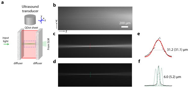
a, Schematic of the experimental setup, consisting of a thin sheet of quantum dots between two strong diffusers. b – d, Fluorescence emission images of the area in y–z plane indicated by dotted square in a. b, Diffuse illumination observed without wavefront manipulation (flat phase display on the SLM). c, TRUE focusing results in an optical focus the size of the ultrasound focus. d, With TROVE, an optical focus the size of an optical speckle is achieved. e, Profile of the TRUE focus width. f, Profile of the TROVE focus width (the number in brackets indicates the calculated resolution after deconvolving the profile with the resolution of the camera imaging the dotted square in a). Black dots are data points. The dotted lines represent profiles of TROVE foci scanned in y (scan locations separated by 10 μm). Scale bar for b–d: 200 μm
A straightforward way to shift the TROVE focus, or access other optical modes at different positions, would be to move the location of the ultrasound foci. This would entail repeating the entire measurement for 1000 diffuser positions. However, the TROVE strategy allows access to multiple optical modes within the ultrasound focus without the need for further acquisition of data.
We note that the location of the TROVE focus is entirely determined by the point at which the shifted ultrasound foci intersect (see above). Thus, by numerically weighing the output wavefronts with respect to each other during post-processing, we can virtually move the point of intersection (and thus the TROVE focus) to any location along the common axis of the shifted ultrasound foci (dotted lines in Figure 3f).
Imaging with the TROVE focus
We demonstrate the TROVE focusing and two-dimensional scanning strategy established above by scanning the TROVE focus in two-dimensions over a 1 μm diameter fluorescent bead (Fig. 4a) placed in a cuvette flanked by strong diffusers. We confirmed that, due to scattering, the bead could not be imaged via conventional epifluorescence (Fig. 4b). To acquire a TROVE image, we used a photomultiplier tube placed outside the sample to collect the backscattered fluorescence signal, excited by the scanned TROVE foci. From the TROVE image acquired, we obtained the point spread functions of 5.7 μm and 5.4 μm in the x and y direction respectively (Fig. 4d). As compared to TRUE focusing 21 we again find a resolution improvement of over six-fold (Fig. 4a).
Figure 4. Point spread function and image acquisition.

a, Epifluorescence image of a single bead. b, Epifluorescence image of a single bead as seen through a diffuser. c, Fluorescence image of single bead obtained by raster-scanning a TRUE focus. d, Fluorescence image of single bead obtained using TROVE focusing and scanning technique with profile of the fluorescent bead in x and y direction. e, Epifluorescence image of two fluorescent beads. f, Epifluorescence image of beads placed behind a diffuser. g, Fluorescence image of single bead obtained by raster-scanning a TRUE focus. h, TROVE focusing and scanning technique resolves the two beads placed between the strong diffusers. Locations of data points indicated by red dots. Data is interpolated for display using bicubic interpolation. Scale bar: 10 μm
We further demonstrate this resolution improvement by scanning two 1 μm fluorescent beads placed 15 μm apart (Fig. 4e). Due to the limited resolution of the TRUE technique, the TRUE image does not resolve the individual beads (Fig. 4g). In comparison, the two beads are well-resolved with TROVE imaging (Fig. 4h).
Discussion
In this work we presented a new method – time reversal of variance-encoded light (TROVE), to focus light at unprecedented, speckle-scale resolution in the diffusive regime. We demonstrated an optical setup that encoded the frequency-shifted speckle field originating from an ultrasound guide-star with a unique variance structure as well as a decoding algorithm that enabled the measurement and subsequent time reversal of individual optical transmission modes between highly diffusive scattering media. We characterized the lateral point spread function of the system to be 5.4 μm by 5.7 μm, a six-fold improvement compared to previous methods 21, 22. Beyond just resolution improvement, TROVE provides a means to computationally access different optical modes within the ultrasound focus, enabling control of optical wavefronts within a scattering sample at speckle-scale resolution. We demonstrated this ability to access different optical modes from a single dataset by two-dimensional scanning and imaging of fluorescent features. It would be straightforward to extend this method to allow three-dimensional scanning and imaging by repositioning the four ultrasound foci to another plane in the third dimension.
The context of two recent papers, published after submission of our manuscript, illustrates the relative advantages and disadvantages of TROVE: Bertolotti et al. present an elegant approach for imaging across scattering media that does not require ultrasound-tagging, but is instead based on the scattering memory effect 23. The reliance on the memory effect is a hurdle for applications in which the memory effect is expected to be small compared to the area of interest (such as in many biological tissues). The approach outlined in our manuscript (TROVE) does not rely on the memory effect and is therefore not bound by this limitation. TROVE has the added feature that it creates an optical focus, hence not only enabling imaging but also photostimulation and image transfer across scattering media. In the other recent publication, Si et al. 24 reported a method based on iterative time reversal across scattering media to achieve a threefold resolution improvement over TRUE. Their approach is well-suited for moderate resolution improvement (~ 12 μm) and provides comparably fast acquisition times. In contrast, our approach requires more acquisitions, but achieves higher resolution.
In essence, the TROVE method uncouples the resolution of the system from the size of the ultrasound guide-star. The resolution of the system is instead fundamentally determined by the size of the optical speckles at the ultrasound plane. Due to the low numerical aperture of illumination in our experiments, the size of the optical speckles was 5 μm (full width at half maximum). The size of the speckles could be made smaller with different illumination configurations to yield higher resolution. However, this would require a corresponding increase in the number of wavefront measurements required, resulting in longer acquisition times.
This is an important trade-off because TROVE is based on optical time reversal, and is thus crucially reliant on the mechanical stability of the sample. Therefore, the duration of wavefront measurements and decoding computations should be shorter than the decorrelation time of the sample. In our demonstration, the time required for the measurement of a data set that enabled us to access a 30 μm by 30 μm field of view was 2 hours. Although current hardware speeds restrict the applicability of our method to mechanically stable samples, we anticipate that this requirement can be significantly relaxed with the advent of faster cameras, spatial light modulators25 and wavefront scramblers such as random lasers26 to allow applications even in dynamic samples such as live biological tissues, which have typical decorrelation times on the order of milliseconds27–29 to seconds30. With these improvements on the horizon, our method paves the way for micrometre-scale optical focusing, imaging and image transfer inside a wide range of highly diffusive media.
Methods
Optical setup
All data shown was acquired using a custom built setup that was based on our previously described work on fluorescence digital time reversal of ultrasound-encoded light (TRUE) imaging 21 (see Supplementary Information for setup diagram): Briefly, a 2.7 W, 532 nm Q-switched laser (Navigator, SpectraPhysics, USA) pulsed at 20 kHz with a pulse width of 7 ns and a coherence length of 7 mm was used as a light source. After passing an optical isolator and a fixed attenuator, it was split into a reference beam and a sample beam. The sample beam was attenuated by a neutral density filter wheel, spatially filtered by a single mode optical fibre (Nufern 460HP, 20 cm length), collimated to a 0.8-mm waist beam and directed onto an optical diffuser disk on a rotation mount. The diffuse light exiting the disk was relayed to the surface of our sample with an irradiance of < 10 mW/mm2. Inside the sample, a fraction of the light was frequency-shifted by an ultrasound transducer (element size: 6.35 mm, focal length: 6 mm; V3330, Olympus NDT, Olympus, USA) operated at 50 MHz. To achieve maximal resolution along the axis of ultrasound propagation, the transducer was driven with short pulses (50 MHz, 100 V peak-to-peak carrier oscillation with a Gaussian pulse envelope of 13 ns full width at half maximum) triggered by the laser Q-switch signal at a fixed delay such that the ultrasound pulses coincided with the laser pulses at the same location, forming an ultrasound focus confined in three dimensions. To translate the ultrasound focus, the transducer was mounted on a three-axis computer-controlled micromanipulator (Sutter Instruments, USA). After passing through the sample, the scattered beam was recombined with the horizontally-polarized reference beam, which had also been frequency-shifted by an acousto-optic modulator (AOM; AFM-502-A1, IntraAction, USA). After passing a horizontally-aligned polarizer and another beamsplitter, the combined beams reached the surface of a phase-only spatial light modulator (SLM; vis-PLUTO, Holoeye, Germany), carefully aligned (1:1 pixel-to-pixel match) to the image plane of a high dynamic range sCMOS camera (pco.edge, PCO AG, Germany).
Detection of fluorescence excitation by time-reversed light
The time-reversed beam was obtained by reflecting the blank reference beam off the SLM displaying the computed phase conjugate map (see also 21). To directly visualize the time-reversed focus, the fluorescence emission from the quantum dot sheet was imaged with a 4x magnification onto a digital camera (Stingray F145, AVT, USA) fitted with a longpass filter (BLP02-561R, Semrock, USA) through the clear window between the scattering media.
This direct access was not utilized in subsequent experiments where fluorescent beads were imaged. For the time reversal of variance-encoded light (TROVE) imaging experiments, the emitted fluorescence that passed back through the scattering medium was reflected off a dichroic mirror (FF541-SDi01, Semrock, USA) and detected by a single-channel photomultiplier tube (H7827-002, Hamamatsu, Japan) fitted with a bandpass filter (FF01-572/28, Semrock, USA). Because of the comparatively low contrast in the TRUE imaging experiments, a camera (Stingray F145, AVT, USA) was used to collect the fluorescence emitted through the clear window between the diffusers. It is important to note that the camera was not used to resolve the bead, but just as a single pixel detector to collect the fluorescence emitted. In TROVE and TRUE scanning experiments, we suppressed the fluorescence excited by the time reversal background with adaptive background subtraction (described in ref 21).
Phase recording
We recorded the frequency-shifted field at the SLM plane and the frequency-shifted field at the ultrasound plane with digital phase-shifting holography 31. The carrier oscillation driving the ultrasound transducer was shifted by 0, π/2, π and 3π/2 phase delay relative to the oscillation driving the reference beam AOM and a frame was acquired for each phase delay. This 4-frame cycle was repeated 10 times and frames recorded at the same phase delay were averaged, resulting in four intensity maps that were used to reconstruct the complex field according to E = (Iπ/2 − I3π/2) + i(I0 − Iπ) (wherever our manuscript refers to amplitude and phase of the complex field, we used amplitude, A, and phase, θ, as in E = A·exp(i·θ) ). To obtain phase maps for each of the four overlapping ultrasound focus locations required for TROVE, we translated the ultrasound focus laterally using the micromanipulator (by 26 μm) and vertically by adjusting the delay of the ultrasound pulses (by 20 ns) versus the laser pulses.
Measurement and calculation of variance encoded modes
We represent the speckled wavefront at the ultrasound by the vector b, which describes the optical field values as a function of position. Part of this wavefront is frequency-shifted via the acousto-optic effect, resulting in a frequency-shifted optical field b′ = b·G (where G denotes a diagonal matrix whose diagonal elements g describe the Gaussian-shaped ultrasound focus). The frequency-shifted optical field b′ propagates through the second section of the scattering medium (mathematically described by the scattering matrix TBC) before leaving the tissue as the output field c = b′·TBC. In other words, c can be described as a linear superposition of many optical transmission modes (or rows in TBC) and the weights of this superposition are given by b′.
By randomizing the input beam to the ultrasound focus, we obtain many possible realizations of b and thus different frequency-shifted wavefronts b′ and c. We can represent each realization of b, b′ and c as rows of the matrices B, B′ and C respectively. Thus, the field recorded outside the sample at each diffuser position (each row in C) will be a different linear combination of transmission modes (rows in TBC) originating from individual optical modes within the ultrasound focus. To resolve the ambiguity due to the symmetry of the ultrasound focus, we move the ultrasound between four overlapping positions (1 – 4), resulting in four slightly shifted ultrasound foci represented by g1, g2, g3 and g4 respectively. Since the data for the four foci are recorded for the same diffuser position in each presentation (or each row in B and C), we get B′1,2,3,4 =B·G1,2,3,4 and C1,2,3,4 = B′1,2,3,4·TBC.
To find a vector for phase conjugation back to a single mode, we looked for a vector v with high variance along the sum C1+C2+C3+C4 (short: C1+2+3+4) and low variances along the differences C1−4 and C2−3. We achieved this by maximizing the ratio of variances Q = v*(C1+2+3+4*C1+2+3+4)v/(v*(C1−4*C1−4 + C2−3*C2−3)v). Since Q is a generalized Rayleigh Quotient, it can be maximized by v = eig[(C1−4*C1−4 + C2−3*C2−3)−0.5(C1+2+3+4*C1+2+3+4) (C1−4*C1−4 + C2−3*C2−3)−0.5 ], where eig[] denotes a function returning the principal eigenvector. Because the size of C is 1000×0.5M in our experiments (number of realizations by number of pixels on the detector), a direct calculation of this eigenvector would involve a 0.5M by 0.5M matrix and would be computationally impractical. In the supplement, we derive an alternative approximation of v that is computationally efficient because it only involves 1000×1000 matrices. To digitally scan the time-reversed focus in space, we addressed different optical modes at the ultrasound focal plane by weighing the datasets C1,2,3,4 with prefactors that virtually moved the intersection point of the Gaussian foci.
Sample
An open-top quartz glass cuvette with four polished sides (Starna Cells, CA) was filled with 2% (wt/wt) agarose gel (Invitrogen, USA). The glass cuvette was flanked on two sides with highly diffusing films (3M Scotch model #810, ~ 60 μm thick) that did not transmit a detectable ballistic component (measured with a detection threshold of less than 10−8 of the transmitted power - see 21 for setup). The quantum dot sheet used to directly visualize the time-reversed foci were made with Qtracker 655 (Non-targeted quantum dots, Invitrogen) diluted in agarose such that the final concentration of quantum dots was 0.4 μM. The 1 μm diameter fluorescent beads (FluoSphere, Orange fluorescent) used for point spread function characterization and imaging demonstration were obtained from Invitrogen, USA.
Supplementary Material
Acknowledgments
The authors thank Dr. Ivo Vellekoop for many helpful discussions and Dr. Phil Willems for comments on the manuscript. BJ is recipient of a Sir Henry Wellcome Fellowship by the Wellcome Trust. YMW acknowledges support from the National Science Scholarship, awarded by the Agency for Science, Technology and Research, Singapore. This work is supported by NIH 1DP2OD007307-01 and DARPA W31P4Q-11-1-0008.
Footnotes
Author Contributions
BJ and YMW contributed equally to this work. BJ conceived the idea. BJ and YMW developed the idea, with the help of RH, AM and CY. BJ and YMW designed the experiment, built the setup, collected data, performed the simulation and data analysis, and wrote the manuscript. RH contributed to the manuscript and to the simulation results. RH and AM contributed to analysis and mathematical derivation. CY supervised the project and contributed to the manuscript.
Competing Financial Interest Statement
The authors declare no competing financial interest.
References
- 1.Mosk AP, Lagendijk A, Lerosey G, Fink M. Controlling waves in space and time for imaging and focusing in complex media. Nat Photonics. 2012;6:283–292. [Google Scholar]
- 2.Freund I. Looking through Walls and around Corners. Physica A. 1990;168:49–65. [Google Scholar]
- 3.Vellekoop IM, Lagendijk A, Mosk AP. Exploiting disorder for perfect focusing. Nat Photon. 2010;4:320–322. [Google Scholar]
- 4.Vellekoop IM, Mosk AP. Focusing coherent light through opaque strongly scattering media. Opt Lett. 2007;32:2309–2311. doi: 10.1364/ol.32.002309. [DOI] [PubMed] [Google Scholar]
- 5.Katz O, Small E, Silberberg Y. Looking around corners and through thin turbid layers in real time with scattered incoherent light. Nat Photonics. 2012;6:549–553. [Google Scholar]
- 6.Katz O, Small E, Bromberg Y, Silberberg Y. Focusing and compression of ultrashort pulses through scattering media. Nat Photonics. 2011;5:372–377. [Google Scholar]
- 7.van Putten EG, et al. Scattering Lens Resolves Sub-100 nm Structures with Visible Light. Phys Rev Lett. 2011;106:193905. doi: 10.1103/PhysRevLett.106.193905. [DOI] [PubMed] [Google Scholar]
- 8.Aulbach J, Gjonaj B, Johnson PM, Mosk AP, Lagendijk A. Control of Light Transmission through Opaque Scattering Media in Space and Time. Phys Rev Lett. 2011;106 doi: 10.1103/PhysRevLett.106.103901. [DOI] [PubMed] [Google Scholar]
- 9.Lerosey G, De Rosny J, Tourin A, Fink M. Focusing beyond the diffraction limit with far-field time reversal. Science. 2007;315:1120–1122. doi: 10.1126/science.1134824. [DOI] [PubMed] [Google Scholar]
- 10.Yaqoob Z, Psaltis D, Feld MS, Yang CH. Optical phase conjugation for turbidity suppression in biological samples. Nat Photonics. 2008;2:110–115. doi: 10.1038/nphoton.2007.297. [DOI] [PMC free article] [PubMed] [Google Scholar]
- 11.Popoff S, Lerosey G, Fink M, Boccara AC, Gigan S. Image transmission through an opaque material. Nat Commun. 2010;1:81. doi: 10.1038/ncomms1078. [DOI] [PubMed] [Google Scholar]
- 12.Popoff SM, et al. Measuring the transmission matrix in optics: an approach to the study and control of light propagation in disordered media. Phys Rev Lett. 2010;104:100601. doi: 10.1103/PhysRevLett.104.100601. [DOI] [PubMed] [Google Scholar]
- 13.Cizmar T, Dholakia K. Exploiting multimode waveguides for pure fibre-based imaging. Nat Commun. 2012;3:1027. doi: 10.1038/ncomms2024. [DOI] [PMC free article] [PubMed] [Google Scholar]
- 14.Choi Y, et al. Scanner-Free and Wide-Field Endoscopic Imaging by Using a Single Multimode Optical Fiber. Phys Rev Lett. 2012;109:203901. doi: 10.1103/PhysRevLett.109.203901. [DOI] [PMC free article] [PubMed] [Google Scholar]
- 15.Choi W, Mosk AP, Park QH, Choi W. Transmission eigenchannels in a disordered medium. Phys Rev B. 2011;83:134207. [Google Scholar]
- 16.Hsieh CL, Pu Y, Grange R, Psaltis D. Digital phase conjugation of second harmonic radiation emitted by nanoparticles in turbid media. Opt Express. 2010;18:12283–12290. doi: 10.1364/OE.18.012283. [DOI] [PubMed] [Google Scholar]
- 17.Vellekoop IM, Cui M, Yang CH. Digital optical phase conjugation of fluorescence in turbid tissue. Appl Phys Lett. 2012;101 doi: 10.1063/1.4745775. [DOI] [PMC free article] [PubMed] [Google Scholar]
- 18.Xu X, Liu H, Wang LV. Time-reversed ultrasonically encoded optical focusing into scattering media. Nat Photonics. 2011;5:154–157. doi: 10.1038/nphoton.2010.306. [DOI] [PMC free article] [PubMed] [Google Scholar]
- 19.Lai P, Xu X, Liu H, Suzuki Y, Wang LV. Reflection-mode time-reversed ultrasonically encoded optical focusing into turbid media. J Biomed Opt. 2011;16:080505. doi: 10.1117/1.3609001. [DOI] [PMC free article] [PubMed] [Google Scholar]
- 20.Liu H, Xu X, Lai P, Wang LV. Time-reversed ultrasonically encoded optical focusing into tissue-mimicking media with thickness up to 70 mean free paths. J Biomed Opt. 2011;16:086009. doi: 10.1117/1.3609004. [DOI] [PMC free article] [PubMed] [Google Scholar]
- 21.Wang YM, Judkewitz B, DiMarzio CA, Yang CH. Deep-tissue focal fluorescence imaging with digitally time-reversed ultrasound-encoded light. Nat Commun. 2012;3 doi: 10.1038/ncomms1925. [DOI] [PMC free article] [PubMed] [Google Scholar]
- 22.Si K, Fiolka R, Cui M. Fluorescence imaging beyond the ballistic regime by ultrasound-pulse-guided digital phase conjugation. Nat Photon. 2012;6:657–661. doi: 10.1038/nphoton.2012.205. [DOI] [PMC free article] [PubMed] [Google Scholar]
- 23.Bertolotti J, et al. Non-invasive imaging through opaque scattering layers. Nature. 2012;491:232–234. doi: 10.1038/nature11578. [DOI] [PubMed] [Google Scholar]
- 24.Si K, Fiolka R, Cui M. Breaking the spatial resolution barrier via iterative sound-light interaction in deep tissue microscopy. Sci Rep. 2012;2 doi: 10.1038/srep00748. [DOI] [PMC free article] [PubMed] [Google Scholar]
- 25.Conkey DB, Caravaca-Aguirre AM, Piestun R. High-speed scattering medium characterization with application to focusing light through turbid media. Opt Express. 2012;20:1733–1740. doi: 10.1364/OE.20.001733. [DOI] [PubMed] [Google Scholar]
- 26.Redding B, Choma MA, Cao H. Speckle-free laser imaging using random laser illumination. Nat Photonics. 2012;6:355–359. doi: 10.1038/nphoton.2012.90. [DOI] [PMC free article] [PubMed] [Google Scholar]
- 27.Draijer M, Hondebrink E, Leeuwen T, Steenbergen W. Review of laser speckle contrast techniques for visualizing tissue perfusion. Lasers Med Sci. 2009;24:639–651. doi: 10.1007/s10103-008-0626-3. [DOI] [PMC free article] [PubMed] [Google Scholar]
- 28.Hajjarian Z, Xi J, Jaffer FA, Tearney GJ, Nadkarni SK. Intravascular laser speckle imaging catheter for the mechanical evaluation of the arterial wall. J Biomed Opt. 2011;16:026005–026005. doi: 10.1117/1.3533322. [DOI] [PMC free article] [PubMed] [Google Scholar]
- 29.Lev A, Sfez B. In vivo demonstration of the ultrasound-modulated light technique. J Opt Soc Am A. 2003;20:2347–2354. doi: 10.1364/josaa.20.002347. [DOI] [PubMed] [Google Scholar]
- 30.Cui M, McDowell EJ, Yang C. An in vivo study of turbidity suppression by optical phase conjugation (TSOPC) on rabbit ear. Opt Express. 2010;18:25–30. doi: 10.1364/OE.18.000025. [DOI] [PMC free article] [PubMed] [Google Scholar]
- 31.Yamaguchi I, Zhang T. Phase-shifting digital holography. Opt Lett. 1997;22:1268–1270. doi: 10.1364/ol.22.001268. [DOI] [PubMed] [Google Scholar]
Associated Data
This section collects any data citations, data availability statements, or supplementary materials included in this article.