

Abstract
Controlling the size distribution of polymer-based nanoparticles is a challenging task due to their flexible core and surface structures. To accomplish such as task requires a very precise control at the molecular level. Here, we demonstrate a new approach whereby uniform-sized supramolecular nanoparticles (SNPs) can be reliably generated using a digital microfluidic droplet generator (DMDG) chip. A microfluidic environment enabled precise control over the processing parameters and, therefore, high batch-to-batch reproducibility and robust production of SNPs with a very narrow size distribution could be realized. Digitally adjusting the mixing ratios of the building blocks on the DMDG chip allowed us to rapidly scan a variety of synthesis conditions without consuming significant amounts of reagents. Nearly uniform SNPs with sizes ranging from 35 to 350 nm were obtained and characterized by transmission electron microscopy and dynamic light scattering. In addition, we could fine-tune the surface chemistry of the SNPs by incorporating an additional building block functionalized with specific ligands for targeting cells. The sizes and surface properties of these SNPs correlated strongly with their cell uptake efficiencies. This study showed a feasible microfluidic-assisted SNP production and provided a great means for preparing size-controlled SNP with desired surface ligand coverage.
1. Introduction
The study of nanoparticles exhibiting unique properties that differ from those observed in corresponding bulk materials has emerged as a growing field of intensive research [1–5]. Over the past two decades, there have been significant efforts devoted to exploring the use of nanoparticles for biomedical applications, especially in molecular imaging of disease and drug/gene delivery [6–10]. Recently, our research group developed a multi-component self-assembly approach toward the preparation of supramolecular nanoparticles (SNPs); this protocol exhibits the advantageous characteristics of synthetic convenience, flexibility, and modularity [11, 12]. The uniqueness of this self-assembly approach is that it allows the surfaces of the SNPs to be decorated with various targeting ligands, while offer flexibility in the selection of many different loadings. The SNPs can also be tailored to meet desired mechanical and functional properties. For example, SNPs can be programmed by simply switching the nature of the building blocks or by mixing them at different ratios, offering the possibility of combining structural diversity with unique functions [11, 12]. In a previous work, we observed size-dependent lymph node uptake of SNPs, with biodistributions also influenced by size [11]. In addition, we have found that the surface chemistry of such nanoparticles dictates their stability, solubility, cell binding specificity, and internalization capability [12]. To control SNP self-assembly, several essential parameters (structures of the building blocks, reaction temperature, pH, concentration) must be varied to determine the optimal conditions for the production of SNPs having desired sizes and surface chemistries. With conventional production methods, however, several major issues often arise: poor reproducibility, tedious synthetic procedures, and nonuniform particles having a wide size distribution [13]. Consequently, the current practice of nanoparticle production is usually time-, labor- and sample-consuming. Further advances in this field will require practical strategies for optimizing and producing SNPs in a highly reproducible matter.
Several examples of nanoparticle syntheses using microfluidic platforms have been reported [14–21]. There are many advantages to using microfluidic platforms, including minimal consumption of building blocks, reduced reaction times, the capability for parallel processing, and the ability to perform multi-step syntheses [22–25]. Most importantly, the quality of the resulting nanoparticles is greatly improved when they are produced within a microfluidic environment [26, 27]. Due to the expected benefits from microfluidics, such as enhanced reaction kinetics, superior reaction control, high production reliability, safety and facile automation and integration with downstream processing, several microfluidic platforms have been developed recently for nanoparticle syntheses [28–34], especially in the format of microdroplet-based microreactors that allow one to compartmentalize and isolate samples and reactants within individual droplets [35–37]. The application of microdroplets enables an unprecedented degree of control over reaction conditions on short time scales [33, 38, 39]. Each droplet becomes an individual, miniature batch reactor, characterized by uniform volume, temperature, and concentration. The various reagents are typically either (i) combined into the multi-component droplets at the instant of droplet formation or (ii) first formed as single-component droplets that are later merged together through on-chip droplet manipulation [32, 33, 40]. Rapid mixing is achieved simply by moving droplets along microchannels or surfaces [41]. The high droplet throughput and well-defined droplet size and reagent composition make microdroplet technology ideal for nanoparticle syntheses.
Several requirements must be met if we are to perform SNP syntheses using self-assembly processes in microfluidic devices: (1) the ratio of all the building blocks must be precisely controlled; (2) the building blocks and final SNPs must be free from contaminants; and (3) the sizes and surface chemistries of the SNPs must readily accommodate different building blocks as well as various mixing ratios [10–12]. To date, no suitable microfluidic devices have been developed that are capable of synthesizing SNPs because they have all been incapable of precisely adjusting the ratio of building blocks or removing the second immiscible phase in the final droplets [28, 32, 33, 42].
In this paper, we report a new approach toward the optimization and synthesis of SNPs using a digital microfluidic droplet generator (DMDG) [42, 43], which permits precise control over the composition and size of multi-component droplets on-demand. In addition, the droplets are separated using nitrogen slugs to avoid contamination, thereby greatly simplify the subsequent purification/dispensing of the resulting SNPs. This DMDG chip provides a very practical platform for optimizing the synthetic parameters and producing uniform SNPs, with narrow size distributions, in a high reproducible manner. We used this DMDG chip to generate SNPs of various sizes and surface chemistries. Subsequent in vitro studies indicated a close relationship between the size/surface chemistry and the cell uptake efficiency.
2, Experimental details
2.1 Materials
Reagents and solvents were purchased from Sigma–Aldrich (St. Louis, MO) and used as received without further purification, unless otherwise noted. Branched polyethyleneimine (PEI; MW = 10 kD) was purchased from Polysciences (Washington, PA); the polymer contained primary, secondary, and tertiary amino groups in a ca. 25:50:25 ratio. A first-generation polyamidoamine (PAMAM) dendrimer featuring a 1,4-diaminobutane core and amino terminal groups was purchased as a 20% wt MeOH solution from Dendritic Nanotechnologies (Mount Pleasant, MI). 1-Adamantanamine (Ad) hydrochloride and β-cyclodextrin (β-CD) were purchased from TCI America (San Francisco, CA). N-Hydroxysuccinimide (SCM) and maleimido (MAL) hetero-functionalized polyethylene glycol (SCM-PEG-MAL; MW = 5 kD) was obtained from NANOCS (New York, NY). 6-Monotosyl-β-cyclodextrin (6-OTs-β-CD) was prepared following the literature method [44]. The octa-Ad–grafted PAMAM dendrimer (Ad-PAMAM, 1 or 1′), CD-grafted branched PEI (CD-PEI, 3), and Ad-grafted polyethylene glycol (Ad-PEG, 2) were prepared using previously reported methods [11]. CH2Cl2 was dried under reflux over CaH2 and freshly distilled prior to use. MCF7 breast cancer and U87 brain cancer cell lines were purchased from American Type Culture Collection. The Dulbecco’s modified Eagle’s medium (DMEM), Earl’s modified Eagle’s medium (EMEM), and penicillin/streptomycin were obtained from Invitrogen (Carlsbad, CA). Fetal bovine serum (FBS) was obtained from Lonza Walkersville (Walkersville, MD). 4′,6-Diamidino-2-phenylindole (DAPI) was purchased from Invitrogen (Carlsbad, CA). Argininylglycylaspartylcysteine (RGDC) was purchased from GenScript (Piscataway, NJ).
CD-PEI-Cy5 4 was synthesized as follows. Cy5-N-hydroxysuccinimidyl ester (0.9 mg, 1.0 μmol, 10.0 equiv.) was added to a solution of CD-PEI 3 (1.7 mg, 0.1 μmol, 1.0 equiv.) in PBS buffer solution (pH 7.2). After stirring at room temperature for 2 h, the mixture was purified through dialysis (Slide-A-Lyzer® dialysis cassette, ThermoFischer, Canoga Park, CA; MWCO: 3 kD) against DI water overnight and lyophilized to yield CD-PEI-Cy5 4 (Supporting information). The degree of Cy5 dye substitution on the CD-PEI 3 backbone was calculated based on the molar extinction coefficient of Cy5 (ε = 250,000 M−1 cm−1), suggesting that there were five to six Cy5 molecules grafted per CD-PEI polymer.
2.2 Microfluidic device design and fabrication
A two-layer polydimethylsiloxane (PDMS) microfluidic device was fabricated using common multilayer soft lithography technology [Figure 1(a)] [45, 46]. The upper and lower layers of the microchannel network functioned as fluidic and control channels, respectively. By applying positive pressure (ca. 450 kPa) via electronic solenoid valves (Series S070, SMC, Japan), the control channels could be deformed, thereby functioning as on-chip microvalves to close the fluidic channels at locations where the control channels directly overlapped the fluidic channels [46]. Figure 1b provides a schematic representation of the main features of the DMDG chip. The core consisted of eight parallel droplet generation units. Each droplet generation unit could be isolated from the surrounding channels by microvalves; the volume of the filling chambers in each droplet generation unit could also be dynamically controlled by using dividing microvalves.
Figure 1.

(a) Photograph of the PDMS microfluidic device. (b) Schematic representation of the main features of the microfluidic device. Each filling region (chambers II–IX) has a length of 1500 μm, a width of 300 μm, a height of 45 μm, and a volume of ca. 15 nL. The volumes of step-filling chambers I are ca. 15, 30, 45, and 60 nL. Two different concentrations of Ad-PAMAM (84 and 168 μM), Ad-PEG (840 μM), CD-PEI (168 μM), and RGD-PEG-Ad (21 μM) were loaded individually into the chip through inlets Ad-PAMAM 1 (84 μM), Ad-PAMAM 1′ (186 μM, Ad-PEG 2, CD-PEI 3 or CD-PEI-Cy5 4, and RGD-PEG-Ad 5, respectively. (c, d) Graphical representations of the on-chip approach toward the preparation of size- and surface chemistry–controllable SNPs 6 and RGD-SNPs 7.
2.3 Production of SNPs 5 in a DMDG chip
Three molecular building blocks, Ad-PAMAM 1 (84 μM) or 1′ (168 μM), Ad-PEG 2 (840 μM), and CD-PEI 3 (168 μM), were used to assemble SNPs 6 [Figure 1(c)]. Eight parallel droplets having desired volumes/ratios of building blocks could be digitally generated by performing one cycle of operation of the mechanically acting microvalves in the DMDG chip. The detailed sequence of valve states used to generate the composition-controlled droplets in each droplet generation unit of the parallel DMDG chip is presented in Figure 2. The process involved seven steps. Step 1: Close all microvalves to initialize the microfluidic device (ca. 50 ms). Step 2: Release the backpressure of the droplet generation unit (ca. 150 ms) by applying a vacuum (ca. −75 kPa). Step 3: Form the desired volume of the reagent filling chambers (ca. 50 ms) by closing the dividing microvalves. Step 4: Fill the individual chambers with the building blocks and PBS by applying a positive pressure (ca. 200 kPa, ca. 150 ms); in this step, the RGD-PEG-Ad 5 building block was not placed into the reagent filling chamber VI. Step 5: Seal the reagent filling chambers (ca. 50 ms). Step 6: Merge reagents to form one droplet (ca. 50 ms). Step 7: Open the trap valve at the end of the droplet generation unit to expel the droplet from the device using nitrogen (ca. 60 kPa). In the parallel droplet generation process, eight droplets could be generated in parallel by sequentially opening the trap valves at the end of each unit (step 7) and expelling them from the microfluidic device using nitrogen (ca. 100 ms for each droplet generation unit). The total time required to generate the eight droplets when using the parallel DMDG chip was ca. 1.3 s. The droplets having desired volumes/ratios of building blocks were expelled and passed through individual tubes into PCR/Eppendorf tubes. Finally, the eight batches of SNPs 6 were produced in parallel simultaneously using the DMDG chip. Each experiment was performed in triplicate.
Figure 2.

Time sequence of the droplet generation process in a single droplet generation unit of the parallel microfluidic device.
Eight different batches of SNPs 6 prepared from different ratios of Ad-PAMAM and CD-PEI were produced by adjusting the volume or concentration of Ad-PAMAM. The first four batches of SNPs 6 were produced by filling Ad-PAMAM 1 (84 μM) alone into the reagent step-filling chamber I and using PBS to fill both filling chambers II and III. Each building block was placed into the destined chamber at a fixed volume to ensure an equal amount of each building block in each droplet. Because chambers I could be sectioned into four different volumes, four different ratios of Ad-PAMAM and CD-PEI (0.5, 1.0, 1.5, and 2.0) were generated to prepare SNPs 6 in four different batches. Next, another four batches of SNPs were produced by filling Ad-PAMAM 1 (84 μM) into the step-filling chamber I and then placing another concentration of Ad-PAMAM 1′ (168 μM) into both filling chambers II and III. Using this approach, another four different batches of SNPs 6 were generated with four different ratios of Ad-PAMAM and CD-PEI (2.5, 3.0, 3.5, and 4.0). By scaling the cycle number of the droplet generation steps, 200-μL samples of SNPs 6 were produced under each set of conditions. In addition to the cases using CD-PEI, the same procedures were also performed using CD-PEI-Cy5 4 (168 μM) to aid visualization.
2.4 Production of RGD-SNPs 7 in a DMDG chip
To explore the biological applications of SNPs, the RGD ligand (argininylglycylaspartic acid), which recognizes the αvβ3 integrin receptor on the membranes of certain types of tumor cells [47], was incorporated onto the surfaces of the SNPs. Four molecular building blocks—Ad-PAMAM 1 (84 μM), Ad-PEG 2 (840 μM), CD-PEI-Cy5 4 (168 μM), and RGD-PEG-Ad 5 (21 μM)—were used to assemble RGD-targeted SNPs [RGD-SNPs 7, Figure 1(d)]. By using a similar operating principle, eight parallel droplets having desired volumes/ratios of building blocks were generated by the DMDG chip. In this case, all the parallel droplets were generated having the same amount of building blocks by filling Ad-PAMAM 1 into chamber III (leaving chambers I and II empty), and Ad-PEG 2 and CD-PEI-Cy5 4 into chambers IV and V, respectively. Four different SNPs having RGD ligand coverage of 0, 2.5, 5, and 10% (based on the total amount of Ad-PEG 2) were created by filling different amounts of RGD-PEG-Ad 5 (21 μM) into chambers VI–IX with volume units of 0, 1, 2, and 4, respectively.
2.5 Characterization of SNPs 5 and RGD-SNPs 6
Dynamic light scattering (DLS) experiments were performed using a Zetasizer Nano instrument (Malvern Instruments, UK) equipped with a 10-mW helium-neon laser (λ = 632.8 nm) and a thermoelectric temperature controller. Measurements were taken at a 90° scattering angle. The morphology and sizes of the SNPs 6 and RGD-SNPs 7 were examined directly using a Philips CM 120 electron microscope operated at an acceleration voltage of 120 kV. Samples for transmission electron microscopy (TEM) were prepared by drop-coating solutions of the SNPs 6 and RGD-SNPs 7 (2 μL) onto carbon-coated copper grids. Excess amounts of the droplets were removed after 45 s using filter paper. The surface-deposited SNPs 6 and RGD-SNPs 7 were then negatively stained with 2% uranyl acetate for 45 s prior to TEM analysis.
2.6 In vitro cell uptake study
U87 cell lines were routinely maintained in DMEM containing 10% FBS and 1% penicillin/streptomycin (Invitrogen, Carlsbad, CA). MCF7 was cultured in DMEM containing 10% FBS and 1% penicillin/streptomycin.
Cells (1 × 10⁴ cells/well) were plated in eight-well chamber slides and left to adhere overnight. The SNPs 6 or RGD-SNPs 7 (4 μM) were added into individual wells containing DMEM (200 μL). SNPs or RGD-SNPs were incubated with the cells for 12 h and then removed by aspirating and washed with PBS (three times). Cells were fixed with 4% paraformaldehyde for 15 min at room temperature, washed with PBS (three times), stained with DAPI, and then rinsed with PBS prior to imaging using a fluorescence microscope.
The eight-well chamber slide was mounted onto a Nikon TE2000S inverted fluorescence microscope equipped with a CCD camera (Photomatrix, Cascade II), X-Cite 120 Mercury lamp, automatic stage, and filters for three fluorescent channels [W1 (DAPI) and W2 (Cy5)]. Following image acquisition, MetaMorph software (Molecular Devices, v. 7.5.6.0) was used to quantify the Cy5 expressed cells. The Multi-Wavelength Cell Scoring module of the MetaMorph software allowed image analysis. A nuclei counting application in the module allowed the total cell number to be calculated. To determine the cell uptake ability, the Cy5 intensities of the individual cells were quantified using the MetaMorph program. The highest fluorescence intensity was observed from the U87 cells treated with 35-nm SNPs with 5% RGD target ligand coverage. This fluorescence intensity was used to normalize other readings as depicted in Figure 4b.
Figure 4.

TEM analyses of size distributions of SNPs 6. SNPs with various sizes (36.7 ± 5.7, 110 ± 9.2, 148 ± 9.5, and 344 ± 15.3 nm) were obtained by varying the mixing ratio of Ad-PAMAM to CD-PEI.
3. Results and discussion
The DMDG chip allowed us to successfully prepare SNPs. Unlike other SNP synthesis processes performed in continuous flow microfluidic devices, we used the digitally controllable microvalves of our DMDG chip to adjust the reagents and building blocks to desired ratios/volumes and to merge them together into end-to-end droplets that could then be mixed after flowing along the mixing channel [41]. In addition, this present approach allowed larger amounts of sample(s) to be produced rapidly by scaling the cycle number of droplet generation steps. Our parallel microfluidic device could not only precisely adjust the ratio of building blocks but also produce four different conditions for the SNPs in parallel (0.5–1 mL/h for each condition) or produce just one condition (2–4 mL/h, without using the reagent step-filling chamber I). Furthermore, because we used nitrogen to separate each droplet, the final SNPs could be applied directly to the next step or to in vitro applications without requiring an oil removal step. Combining all the advantages mentioned above allowed us to readily evaluate small “batches” of samples (e.g., several droplets) through TEM analyses.
In a previous study, we found that the sizes of the SNPs depended on the mixing ratio of Ad-PAMAM and CD-PEI [11]. Using the DMDG chip, we produced eight SNPs 6 from different mixing ratios of Ad-PAMAM and CD-PEI by adjusting the volume of the Ad-PAMAM building block. Figure 3(a) reveals that the average size of the SNPs increased upon increasing the molar ratio of Ad-PAMAM to CD-PEI. When we increased the ratio of Ad-PAMAM to CD-PEIfrom 0.5 to 4, the mean size (DLS) of the SNPs increased continuously from 36 ± 4.9 to 443 ± 21.3 nm, primarily because of the increased degree of cross-linking between the Ad-PAMAM and CD-PEI units. We observed similar trends in previous studies [11, 12]. In addition to the DMDG chip producing precisely size-controlled SNPs 6, it also provided a high reproducibility for each SNP synthesis. Under the same conditions, the “mean” size differences of the SNPs obtained from different batches were quite small [from 3.8 to 13.5%; see the error bars in Figure 3(a)]. This reproducible microfluidic-assisted SNP production presumably arose from the precise control exerted over the volume/ratio of each building block and over the reaction parameters within the microfluidic device [32, 33]. The resulting SNPs 6 possessed spherical morphologies, with sizes consistent with those determined using DLS [Figures 3(b–e)].
Figure 3.
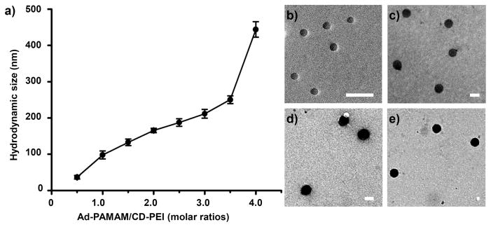
(a) Relationship between the sizes of the SNPs 6 and the ratio of Ad-PAMAM/CD-PEI, obtained through DLS analysis. (b–e) TEM images of SNPs 6 having sizes of 36.7 ± 5.7, 110 ± 9.2, 148 ± 9.5, and 344 ± 15.3 nm, obtained at Ad-PAMAM/CD-PEI ratios of 0.5, 1.5, 2.5, and 4.0 respectively. Scale bar: 100 nm.
Using our DMDG chip, microdroplets were generated in an end-to-end manner very precisely; they could be mixed rapidly upon moving along a straight channel. Unlike other precisely tuned continuous-flow droplet generators that can perform mixing in only a single ratio (or alternate between two or more different ratios), our system provided complete control over a wide range of droplet ratios, even changing the mixing ratio on demand. Its multi-chamber design enabled us to perform simultaneous mixing of multiple reagents over a wide range of ratios; its parallel channel design improved the rate of product output. We fitted the size and size distribution data of the SNPs 6 (n = 200), obtained from TEM analysis, to individual Gaussian curves using the Origin software package (Origin 6.0); the correlation coefficients were all greater than 0.95 (Figure 4). For Ad-PAMAM/CD-PEI ratios of 0.5, 1.5, 2.5, and 4.0, the peak positions (mean sizes of the SNPs 6 synthesized using the DMDG chip) determined using the Origin software package were 36.7, 110, 148, and 344 nm, respectively, and full widths at half maximum (FWHMs; 11.4, 18.4, 19.1 and 30.7 nm, respectively) that are narrower than those obtained using conventional methods (15.8, 26.6, 27.2, and 45.8 nm, respectively) [11, 12]. We attribute this narrower size distribution for the SNPs 6 to the rapid and homogeneous mixing microenvironment afforded by the DMDG chip (see Table S1 in supporting information). It is well documented [33, 41] that multiple reagents combined in an end-to-end format in droplets are rapidly mixed as they flow through microfluidic channels. Taking advantage of an internal recirculation flow pattern, the three building blocks (Ad-PAMAM, Ad-PEG, and CD-PEI) were mixed thoroughly after moving along the microfluidic channel and tubes (>10 cm distance) with high flow rates (>10 cm/s)—on timescales as fast as milliseconds [33, 41]. Using this droplet-based approach prevented the aggregation of SNPs and provided highly homogeneous mixed solutions within a short period of time for the rapid self-assembly of SNPs having uniform sizes. Indeed, SNPs of different sizes were simply and reproducibly synthesizable through programmed adjustment of the filling chamber volumes of Ad-PAMAM in the microfluidic device. The entire operation could be performed very smoothly, reliably, and predictably—even on the very first attempt; it did not require any special tuning procedure to arrive at a stable flow of the correct reagent ratio, as in the case of continuous flow systems. Therefore, our DMDG chip platform is capable of digitally generating mircodroplets in a high efficient matter (in seconds) and, at the same time, conserving the reagents.
Next, we produced SNPs 6 of various sizes to perform a cell uptake study. It is currently believed that the optimal diameter of nanoparticle-based therapeutics for cancer therapy should be between 10 and 100 nm. This lower boundary was established based on measurement of sieving coefficients for the glomerular capillary wall; it is estimated that the threshold for first-pass elimination by the kidneys is ca. 10 nm [48]. The upper boundary, however, is not as well defined at present. To visualize the SNP traffic in the cells, we used CD-PEI-Cy5, rather than CD-PEI, to assemble the SNPs in the latter experiments. According to the cell uptake experimental data in Figure 5(a), it appears that smaller-sized SNPs (i.e., 35-nm SNPs) were taken up more readily by the U87 cells after incubation for 12 h at 37 °C (5% CO2). Furthermore, because the surface chemistry of nanoparticles affects their cell-specific uptake efficiency [1], we introduced the RGD target ligand, which recognizes αvβ3 integrin receptors on the membranes of certain types of tumor cells [47], to functionalize the SNPs 6; we then tested their cell-specific uptake efficiency. By varying the mixing ratio of RGD-PEG-Ad with respect to the other building blocks, we obtained 35-nm RGD-SNPs 7 having RGD ligand coverages of 0, 2.5, 5, and 10% (based on the Ad-PEG) in the DMDG chip [Figure 1(d)]. We fed the resulting RGD-SNPs 7 into both αvβ3-positive U87 and αvβ3-negative MCF7 cells [12]. After incubation for 12 h, the 35-nm RGD-SNPs 7 having 5% RGD coverage exhibited the highest cell uptake efficiency [Figure 5(b)]. The fluorescence intensity was stronger in the αvβ3 integrin–positive U87 cells than that in the αvβ3 integrin–negative MCF7 cells [cf. Figures 5(b) and (c)]. Thus, the 35-nm RGD-SNPs 7 having 5% RGD ligand coverage exhibited significantly improved αvβ3 integrin–dependent cell uptake behavior.
Figure 5.

(a) Uptake efficiency of SNPs of various sizes (from 35 to 350 nm) by the U87 cell line. (b) Uptake of 35-nm RGD-SNPs of various RGD ligand coverages (from 0 to 10%) by U87 and MCF7 cell lines. (c) Fluorescence microscopy images of 35-nm RGD-SNPs 7 (5% RGD ligand coverage) taken up by U87 and MCF7 cell lines. The cell nuclei were stained by DAPI; the RGD-SNPs 7 were labeled with Cy5 units.
4. Conclusion
We have developed a microfluidic approach toward producing size- and surface chemistry–controlled SNPs, merely by adjusting the ratios of the building blocks with high flexibility and reducibility. Using our method, SNPs with different compositions can be generated and screened at high speed (>2 seconds per condition) using only very small amount of samples (< 1 μL per condition). Compared with conventional methods, the size distributions of our SNPs were narrow because of the homogeneous assembly within microfluidic environment and the precise control exerted over the mixing ratios of the building blocks. Our methodology produced a collection of uniform SNPs having different sizes and surface chemistries; in vitro experiments indicated that these features were correlated strongly with the cell uptake efficiency. We envision this method could be widely applicable to high-speed screening of optimal conditions to make desired nanoparticulate composites for gene/drug delivery system and molecular imaging [49].
Supplementary Material
Acknowledgments
We thank the US Department of Energy (DE-PS02-09ER09-08, DE-PS02-09ER09-18) and the UC Discovery Grant (bio07-10665, bio08-129095) for financial support.
References
- 1.Cheon J, Lee JH. Acc Chem Res. 2008;41:1630–40. doi: 10.1021/ar800045c. [DOI] [PubMed] [Google Scholar]
- 2.Murphy CJ, Gole AM, Stone JW, Sisco PN, Alkilany AM, Goldsmith EC, Baxter SC. Acc Chem Res. 2008;41:1721–30. doi: 10.1021/ar800035u. [DOI] [PubMed] [Google Scholar]
- 3.Stewart ME, Anderton CR, Thompson LB, Maria J, Gray SK, Rogers JA, Nuzzo RG. Chem Rev. 2008;108:494–521. doi: 10.1021/cr068126n. [DOI] [PubMed] [Google Scholar]
- 4.Nie SM, Xing Y, Kim GJ, Simons JW. Annu Rev Biomed Eng. 2007;9:257–88. doi: 10.1146/annurev.bioeng.9.060906.152025. [DOI] [PubMed] [Google Scholar]
- 5.Shenhar R, Norsten TB, Rotello VM. Adv Mater. 2005;17:657–69. [Google Scholar]
- 6.Davis ME, Chen Z, Shin DM. Nat Rev Drug Discov. 2008;7:771–82. doi: 10.1038/nrd2614. [DOI] [PubMed] [Google Scholar]
- 7.Liu TY, Hu SH, Liu DM, Chen SY, Chen IW. Nano Today. 2009;4:52–65. [Google Scholar]
- 8.Ofir Y, Samanta B, Rotello VM. Chem Soc Rev. 2008;37:1814–23. doi: 10.1039/b712689c. [DOI] [PubMed] [Google Scholar]
- 9.Byrne JD, Betancourt T, Brannon-Peppas L. Adv Drug Deliver Rev. 2008;60:1615–26. doi: 10.1016/j.addr.2008.08.005. [DOI] [PubMed] [Google Scholar]
- 10.Green JJ, Langer R, Anderson DG. Acc Chem Res. 2008;41:749–59. doi: 10.1021/ar7002336. [DOI] [PMC free article] [PubMed] [Google Scholar]
- 11.Wang H, Wang ST, Su H, Chen KJ, Armijo AL, Lin WY, Wang YJ, Sun J, Kamei K, Czernin J, Radu CG, Tseng HR. Angew Chem Int Ed. 2009;48:4344–48. doi: 10.1002/anie.200900063. [DOI] [PMC free article] [PubMed] [Google Scholar]
- 12.Wang H, Chen KJ, Wang ST, Ohashi M, Kamei KI, Sun J, Ha JH, Liu K, Tseng HR. Chem Commun. 2010;46:1851–53. doi: 10.1039/b923711a. [DOI] [PMC free article] [PubMed] [Google Scholar]
- 13.Hawker CJ, Wooley KL. Science. 2005;309:1200–05. doi: 10.1126/science.1109778. [DOI] [PubMed] [Google Scholar]
- 14.He P, Greenway G, Haswell SJ. Nanotechnology. 2008;19:315603. doi: 10.1088/0957-4484/19/31/315603. [DOI] [PubMed] [Google Scholar]
- 15.Singh A, Limaye M, Singh S, Lalla NP, Malek CK, Kulkarni S. Nanotechnology. 2008;19:245613. doi: 10.1088/0957-4484/19/24/245613. [DOI] [PubMed] [Google Scholar]
- 16.Duraiswamy S, Khan SA. Small. 2009;5:2828–34. doi: 10.1002/smll.200901453. [DOI] [PubMed] [Google Scholar]
- 17.Abou-Hassan A, Bazzi R, Cabuil V. Angew Chem Int Ed. 2009;48:7180–83. doi: 10.1002/anie.200902181. [DOI] [PubMed] [Google Scholar]
- 18.Wang HZ, Li XY, Uehara M, Yamaguchi Y, Nakamura H, Miyazaki MP, Shimizu H, Maeda H. Chem Commun. 2004:48–49. doi: 10.1039/b310644f. [DOI] [PubMed] [Google Scholar]
- 19.Weng CH, Huang CC, Yeh CS, Lei HY, Lee GB. Microfluid Nanofluid. 2009;7:841–48. [Google Scholar]
- 20.Day D, Gu M. Nanotechnology. 2009;20:169801. doi: 10.1088/0957-4484/20/16/169801. [DOI] [PubMed] [Google Scholar]
- 21.Luan WL, Yang HW, Tu ST, Wang ZM. Nanotechnology. 2007;18:175603. [Google Scholar]
- 22.Hong JW, Quake SR. Nat Biotechnol. 2003;21:1179–83. doi: 10.1038/nbt871. [DOI] [PubMed] [Google Scholar]
- 23.Park JI, Nie Z, Kumachev A, Abdelrahman AI, Binks BR, Stone HA, Kumacheva E. Angew Chem Int Ed. 2009;48:5300–04. doi: 10.1002/anie.200805204. [DOI] [PubMed] [Google Scholar]
- 24.deMello AJ. Nature. 2006;442:394–402. doi: 10.1038/nature05062. [DOI] [PubMed] [Google Scholar]
- 25.Adamson DN, Mustafi D, Zhang JXJ, Zheng B, Ismagilov RF. Lab Chip. 2006;6:1178–86. doi: 10.1039/b604993a. [DOI] [PMC free article] [PubMed] [Google Scholar]
- 26.Hwang DK, Dendukuri D, Doyle PS. Lab Chip. 2008;8:1640–47. doi: 10.1039/b805176c. [DOI] [PubMed] [Google Scholar]
- 27.Hung LH, Choi KM, Tseng WY, Tan YC, Shea KJ, Lee AP. Lab Chip. 2006;6:174–78. doi: 10.1039/b513908b. [DOI] [PubMed] [Google Scholar]
- 28.Nguyen NT, Wu ZG. J Micromech Microeng. 2005;15:R1–R16. [Google Scholar]
- 29.Wan Z, Yang HW, Luan WL, Tu ST, Zhou XG. Nanoscale Res Lett. 2010;5:130–37. doi: 10.1007/s11671-009-9454-z. [DOI] [PMC free article] [PubMed] [Google Scholar]
- 30.Nakamura H, Tashiro A, Yamaguchi Y, Miyazaki M, Watari T, Shimizu H, Maeda H. Lab Chip. 2004;4:237–40. doi: 10.1039/b310915a. [DOI] [PubMed] [Google Scholar]
- 31.Murphy ER, Martinelli JR, Zaborenko N, Buchwald SL, Jensen KF. Angew Chem Int Ed. 2007;46:1734–37. doi: 10.1002/anie.200604175. [DOI] [PubMed] [Google Scholar]
- 32.Teh SY, Lin R, Hung LH, Lee AP. Lab Chip. 2008;8:198–220. doi: 10.1039/b715524g. [DOI] [PubMed] [Google Scholar]
- 33.Song H, Chen DL, Ismagilov RF. Angew Chem Int Ed. 2006;45:7336–56. doi: 10.1002/anie.200601554. [DOI] [PMC free article] [PubMed] [Google Scholar]
- 34.Chan EM, Mathies RA, Alivisatos AP. Nano Lett. 2003;3:199–201. [Google Scholar]
- 35.Liu K, Ding HJ, Chen Y, Zhao XZ. Microfluid Nanofluid. 2007;3:239–43. [Google Scholar]
- 36.Liu K, Ding HJ, Liu J, Chen Y, Zhao XZ. Langmuir. 2006;22:9453–57. doi: 10.1021/la061729+. [DOI] [PubMed] [Google Scholar]
- 37.Hettiarachchi K, Talu E, Longo ML, Dayton PA, Lee AP. Lab Chip. 2007;7:463–68. doi: 10.1039/b701481n. [DOI] [PMC free article] [PubMed] [Google Scholar]
- 38.Abou-Hassan A, Sandre O, Neveu S, Cabuil V. Angew Chem Int Ed. 2009;48:2342–45. doi: 10.1002/anie.200805933. [DOI] [PubMed] [Google Scholar]
- 39.Shestopalov I, Tice JD, Ismagilov RF. Lab Chip. 2004;4:316–21. doi: 10.1039/b403378g. [DOI] [PubMed] [Google Scholar]
- 40.Zeng SJ, Li BW, Su XO, Qin JH, Lin BC. Lab Chip. 2009;9:1340–43. doi: 10.1039/b821803j. [DOI] [PubMed] [Google Scholar]
- 41.Rhee M, Burns MA. Langmuir. 2008;24:590–601. doi: 10.1021/la702575j. [DOI] [PubMed] [Google Scholar]
- 42.Liu K, Chen YC, Tseng HR, Shen KF, van Dam RM. Microfluid Nanofluid. 2010 doi: 10.1007/s10404-010-0617-0. [DOI] [PMC free article] [PubMed] [Google Scholar]
- 43.Liu K, Lepin EJ, Wang MW, Guo F, Lin WY, Chen YC, Sirk SJ, van Dam RM, Wu AM, Shen KF. Mol Imaging. 2010 doi: 10.2310/7290.2010.00043. [DOI] [Google Scholar]
- 44.Petter RC, Salek JS, Sikorski CT, Kumaravel G, Lin FT. J Am Chem Soc. 1990;112:3860–68. [Google Scholar]
- 45.Melin J, Quake SR. Annu Rev Biophys Biomol Struct. 2007;36:213–31. doi: 10.1146/annurev.biophys.36.040306.132646. [DOI] [PubMed] [Google Scholar]
- 46.Unger MA, Chou HP, Thorsen T, Scherer A, Quake SR. Science. 2000;288:113–6. doi: 10.1126/science.288.5463.113. [DOI] [PubMed] [Google Scholar]
- 47.Liu Z, Cai WB, He LN, Nakayama N, Chen K, Sun XM, Chen XY, Dai HJ. Nat Nanotechnol. 2007;2:47–52. doi: 10.1038/nnano.2006.170. [DOI] [PubMed] [Google Scholar]
- 48.Venturoli D, Rippe B. Am J Physiol. 2005;288:F605–13. doi: 10.1152/ajprenal.00171.2004. [DOI] [PubMed] [Google Scholar]
- 49.Wang H, Liu K, Chen K-J, Lu Y, Wang S, Guo F, Lin W-Y, Kamei K-I, Chen Y-C, Ohashi M, Wang M, Zhao X-Z, Shen CK-F, Tseng H-R. ACS Nano. 2010 doi: 10.1021/nn101908e. accepted. [DOI] [PMC free article] [PubMed] [Google Scholar]
Associated Data
This section collects any data citations, data availability statements, or supplementary materials included in this article.